1
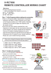
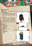
INSTRUCTION MANUAL- SLEEVE SETTER
NMB SPLICE SLEEVE SYSTEM- REINFORCING BAR CONNECTOR
REVISED 2014
38777 W 6 Mile Road, Suite 205
Livonia, MI 48152
www.splicesleeve.com
January 2014
NMB SPLICE-SLEEVE SYSTEM WITH ACCESSORIES
Shaft
SR (Setter Rubber)
SW (Setter Washer)
Cam
Quick pin
Sleeve Setter
Hole Seal
14 MM
22 MM
Bushing
PVC tube
Set Screw(option)
GRW Washer
NMB Splice Sleeve
1
RP(Rubber Plug)
CAM-TYPE SLEEVE SETTER (STR-CT): DETAILS
Figure A: Details of CAM Type Sleeve Setter
It is important to use a rod that fits the socket else flaring of the hole will occur resulting in reduced life of
tool. The hole size is 13 mm or about 1/2 inch.
A: Distance between Socket end and shaft end
B: Distance between Cam-top and the shaft end
C: Height of bushing
D: Thickness of casting forms to be used
E: Height of SR (Setter Rubber)
F: Thickness of SW (Setter Washer)
G: Height of Nut
H: Inside Diameter of Socket
J: Outside Diameter of Setter Shaft
L: Overall Length of Setter Shaft
Figure B: Dimension Details of CAM Type Sleeve Setter
Table 1: Dimensions of Sleeve Setter CAM Type (STR-CT)
STR-CT #
5,6,& 7
8,9,10,11,14,
& 18
A, inch
(mm)
B, inch
(mm)
C, inch
(mm)
1-1/4
(32)
1-3/4
(45)
1.00
(25)
1-1/4
(32)
1-3/4
(45)
1.00
(25)
D, inch
(mm)
E, inch
(mm)
F, inch
(mm)
...
1-5/32
(30)
6/32
(4.5)
9/16
(15)
...
1-3/4
(45)
6/32
(4.5)
9/16
(15)
2
G, inch
(mm)
H, inch
(mm)
J, inch
(mm)
L, inch
(mm)
1/2
(13)
5/8
(16)
7-1/16
(180)
1/2
(13)
5/8
(16)
7-1/16
(180)
INSTALLATION OF SLEEVES WITH CAM-TYPE SLEEVE SETTER (STR-CT)
Procedure of installation of sleeves with CAM type sleeve setter:
1. Remove the Quick-pin from the shaft along with the
cam and bushing.
2. Install the setter rubber, washer and nut on the
shaft and insert the assembly through the hole in
the mold from the inside of the form.
3. Place the bushing over the end of the shaft, and
reassemble the cam to the shaft with the pin. Rotate
the cam so that the cam shaft is parallel to outside
face of the mold.
4. Tighten the nut with a wrench until the side edge of
the cam, when parallel to the outer head of the
bushing, is approximately 1/8” (3 mm) - 7/32" (5
mm) from the outer head of the bushing. Do not
move the nut once it is set in position.
5. Place the wide end of the sleeve over the setter
rubber until it contacts the side of the mold. Insert a
lever rod into the socket of the cam shaft, and rotate
the cam so that the cam shaft is perpendicular to the
face of the mold. Test for proper fit by attempting to
twist sleeve. If loose, go back to step 4 and tighten
nut.
6. Insert the rebar until it contacts the Rebar Stop in the
Sleeve, and secure the rebar in position.
Note: In order to strip the precast element from the mold, the shaft/rubber can be pushed into the
sleeve and retrieved later.
3
LOOSENING THE CAM OF SLEEVE SETTERS
After pouring concrete into the mold, and before Steam-Curing, loosen the cam of sleeve setter. This helps
lengthen the service life of the Setter Rubber.
Figure C: Loosening of CAM Setters
REMOVING SLEEVE SETTERS
Method A: Remove the side mold with the Sleeve Setter.
Figure D: Removal of Sleeve Setters
Method B: Remove the cam and bushing. Push shaft into sleeve. Remove the side form. Remove the shaft
and Rubber from the sleeve. This method is not applicable for 5 U-X through 7 U-X due to the long shaft
length.
4
PIN TYPE SLEEVE SETTER: DETAILS
The second option for setting NMB Splice Sleeves in the mold is the Pin Setter. The Pin Setter uses three
“setter pins” to extend up inside of the shell of NMB Splice Sleeves, grasping the rim or lip at the opening
and holding the sleeve with a tight metal-to-metal connection.
The Pin Setter is characterized by easy and fast installation, high durability and cost-saving option (just
replace rubber ring and washer when worn out). Pin Setter’s metal head and pins can keep NMB Splice
Sleeve tight and straight to the mold with no drooping.
The Pin Setter is currently available in two size ranges:
PS0810 – to be used for sleeve sizes 8, 9, and 10. PS1114 – to be used for sleeve sizes 11 and 14. The size
should be specified along with the component when ordering e.g. PS0810.
Characteristics of Pin Setters:
1. Ease and fast installation
2. Hard and durable. The only nonmetal items are the inexpensive Rubber Ring and Rubber Washer.
3. Pin Setter’s metal head and pins keep the sleeves firm and straight to the molds-even better than the
existing Cam-Lock with Rubber Sleeve Setters.
4. Two pin setters to replace five Cam-Lock Sleeve Setters saving money and space.
The different components of Pin Setter are shown in the Figure III-15 below:
Rubber Ring (PRR)
Hex Nut
Rubber Washer (PRW)
Shaft
Head
Pins (PSP)
Pin Setter Assembly
Figure III-15: Details of PIN Type Sleeve Setter
5
Steel Washer
Table III-3: Dimension of Sleeve Setter Pin Setter Type
Pin Setter
Head
Diameter,
inch (mm)
Head Height,
inch (mm)
Length of Hex
Nut, inch
(mm)
Length of
Shaft,
Inch (mm)
Overall Length
of Pin Setter,
inch (mm)
PS0810
1-5/8”
(42)
1-1/4”
(32)
2-3/8”
(60)
3-3/8”
(85)
4-1/2”
(115)
PS1114
2-1/16”
(53)
1-1/2”
(37.5)
2-3/8”
(60)
3-3/8”
(85)
4-1/2”
(115)
INSTALLATION OF NMB SLEEVES WITH PIN SETTER
Procedure for installation of sleeves with Pin Setter:
Step 1: Install Pin Setter to the mold
1. Drill a ¾” hole on the mold for installing Pin Setter
2. Loosen a hex nut and take out the steel washer
3. Insert the Pin Setter shaft with setter head and rubber
washer to the hole inside on the mold
4. Insert the steel washer into the shaft if the wooden mold
is used. No need to use the steel washer for the metal
mold (optional).
5. Tighten a hex nut into the shaft on the outside of the
mold
Step 2: Set NMB Splice Sleeve
6. Place the wide end of NMB Splice Sleeve over the setter
head and then press hard against the rubber washer into
the mold
7. Lightly tighten a hex nut
Step 3: Tighten a Hex Nut
8. Tighten a hex nut by hand or using electric wrench until
the setter pins extends up into the inside shell of NMB
Splice Sleeve. Make sure the sleeve is properly and
firmly secured in the mold. Do NOT use an impact
wrench for tightening.
Figure III-16: Installation of PIN Type
Sleeve Setter at Precast Plant
Removing Pin Setter
With the same way as the Cam-type sleeve setter, after pouring concrete into the mold and before SteamCuring, remove the side mold with pin setter. This helps prolong the service life of the pin setter.
6
POSSIBLE LEAKAGE LOCATIONS AND ITS REMEDIES
Before pouring concrete into the molds, inspect the following points where concrete or slurry may intrude
into the sleeves during concreting:
Possible Leakage Location
Remedy
A
Between foam plug and sleeve
Wrap with more plastic tape
B
Between rubber plug and rebar
Tie with tie-wire or wrap with duct tape
C
Between grout tubes and ports
Apply sufficient adhesive or wrap with plastic tape
D
At ends of grout tubes
Seal with hole seals or duct tape
E
Between setter rubber and sleeve end
Tighten the sleeve setter
Figure III-22: Possible Leakage Locations
INSPECTION BEFORE POURING CONCRETE
Check the following prior to pouring of concrete:
1. Sleeves in place are the proper size corresponding to drawings. Sleeves are free from dirt.
2. Correct size rubber plugs (RP) are tightly fitted on sleeves and rebars. Tie wires are tied around the
small end of the rubber plug over the rebar contact area for oversize or up-size sleeve applications
where the sleeve is two sizes or more larger than the bar.
3. Sleeves are properly and firmly secured in the mold.
4. Rebars are up against the rebar stops. Check that bar marks are next to End Cap rubber plug.
5. After assuring that the bars are up against the rebar stops, check to see that the lengths of rebars
protruding from the mold are within the allowable tolerances. Long bars may be cut back later. Short
bars must be replaced before casting.
6. Reinforcing bars and sleeves are held in position and properly supported with chairs, etc.
7. Grout tubes are securely attached on the sleeve and sealed properly with Hole Seals. (Grease Hole Seal
cups, if needed)
8. Grout tubes are long enough to reach to or through the firm and are securely fastened at the forms.
For further details refer to Splice Sleeve User’s Manual or call Splice Sleeve directly for assistance.
7