1
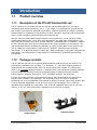
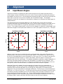
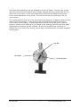
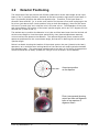
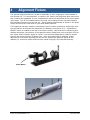
PCI-HC10m User Guide Rev B (June 2014) Port City Instruments, LLC 2764 N Green Valley Pkwy, #538 Henderson, NV 89014 (Tel) 866-456-2488 (Web) www.portcityinstruments.com Copyright © 2013 Port City Instruments, LLC. All Rights Reserved. This document may not be copied, disclosed, transferred, or modified without the prior written consent of Port City Instruments, LLC. Port City Instruments, LLC reserves the right to modify the products and product specifications described in this manual without advance notice. Trademarks Any trademarks, logos, and service marks displayed in this manual are the property of Port City Instruments, LLC or other third parties. Users are not permitted to use these marks without the prior written consent of the company. All other trademarks mentioned in this document are the property of their respective owners. Document Change History Rev # Date Changes Document Created A March 2013 Initial Release. B June 2014 Solid tube fabrication (no brazing), new far mirror design. Contents 1 INTRODUCTION .......................................................................................................................................... 1 1.1 PRODUCT OVERVIEW ................................................................................................................................ 1 1.1.1 Description of the PCI-HC10m Herriottt cell ...................................................................................... 1 1.1.2 Package contents ................................................................................................................................. 1 1.2 USER GUIDE OVERVIEW ............................................................................................................................ 2 2 ALIGNMENT ................................................................................................................................................ 3 2.1 2.2 3 INPUT BEAM ANGLES ............................................................................................................................... 3 DETECTOR POSITIONING........................................................................................................................... 5 KAPTON HEATER ....................................................................................................................................... 6 3.1 INSTALLING THE HEATING ELEMENT ........................................................................................................ 6 4 ALIGNMENT FIXTURE .............................................................................................................................. 7 5 CLEANING THE MIRRORS ....................................................................................................................... 8 APPENDIX A: THERMISTOR R VS T DATA ................................................................................................... 9 i PCI-HC10m 1 Introduction 1.1 Product overview 1.1.1 Description of the PCI-HC10m Herriottt cell The PCI-HC10m is a 34-pass Herriott cell with an optical pathlength of 10.1m that is compatible with lasers operating in the 1 - 5 μm range. It is designed for general lab use and is easily mounted to a standard optical table. Optional accessories include a matched Kapton heater for operation at temperatures to 85C (controller required), and an alignment fixture to aid in aligning infrared beams to the Herriott cell. Herriott cells are named after Donald Herriott, who utilized them in the 1960s to create folded optical delay lines. They were soon adopted for long path laser spectroscopy, and are preferrable to White cells when a small diameter, collimated beam is available. Details on their development and various configurations are widely available on the internet. This user guide describes the procedures necessary to couple a laser beam to the Herriott cell, how to locate the output spot for placement of a detector, and some basic cleaning procedures. It is assumed that the reader has a basic knowledge of long-path spectroscopy using lasers, the manipulation of laser beams in the laboratory, and basic gas handling procedures. 1.1.2 Package contents The PCI-HC10m Herriott cell is shipped assembled and prealigned, with two 10K at 25C thermistors mounted to the cell body. A 1" diameter, 2-7 mm thick coupling window is required and can be ordered from Port City Instruments (part number PCI-HC10m-W), which is an uncoated sapphire wihdow, 1" diameter and 3 mm thickness. Suitable windows are also available from most of the large optical supply companies such as Thorlabs, Edmund Optics, Newport, and others. Thin, AR coated windows, are preferred. If either the heater element or the alignment fixture were ordered with the Herriott cell, they are also included in the package. The alignment fixture is a bolt-on assembly containing two 20 mm adjustable irises placed to define the correct input beam angles, and a tool to facilitate adjustment of the far mirror within the cell flange. Rev A cells are adjusted using a special tool (provided). Rev B cells are adjusted either with a 3/8" hex wrench, or a 7/16" open end wrench, depending on the far mirror design. Alignment Fixture Kapton Heater Port City Instruments, LLC 1 PCI-HC10m 1.2 User guide overview This user guide provides instructions for setting up the Herriott cell and confirming that the input laser beam is properly aligned to it. It is assumed that the Herriott cell is mounted to a flat surface such as an optical table, and that the input beam is directed into the Herriott cell using suitable beam steering optics. If the thermostatting kit was ordered, please follow the instructions for installing the heating element and adjusting the set point as described in chapter 3. Allow the Herriott cell to stabilize at the desired set point temperature before beginning the alignment process. It is recommended that a visible laser be utilized for initial alignment as the output spot from the Herriott cell can be viewed directly on a piece of paper held at the expected output spot position. With near-infrared lasers there are also viewing cards available which can show the output spot clearly. For longer wavelength lasers that are not visible with a view card, it is convenient to combine a visible "tracer" beam with the infrared beam via suitable optics so that the beams are co-linear Throughout this manual the mirror adjacent to the coupling window will be referred to as the "near" mirror, and the mirror at the opposite end of the cell as the "far" mirror. The near mirror has an off-axis hole through which the input laser beam is directed. The far mirror has no hole and is a normal plano-concave mirror. Table 1: PCI-HC10m Specifications PCI-HC10m Optical Pathlength 10.13 m Cell Volume 0.24 L Number of Passes 34 f-number 5.2 Entrance Slopes 2.07 degrees Coupling Hole Diameter 3.25 mm Maximum Beam Diameter 3.0 mm Spot Spacing 4.4 mm Mirror Surface Figure 1/10 wave at 633 nm Mirror Scratch-Dig 20-10 Mirror Coating Gold with protective HfO2 overcoat Cell Material Nickel-plated aluminum O-Ring Material Viton Thermistors 10K @ 25C (Beta = 3977, Vishay part number NTCASCWE3103J) Flow Ports 1/8" NPT threaded female ports Overall Dimensions 13.4" length, 2.5" flange diameter 2 Port City Instruments, LLC 2 Alignment 2.1 Input Beam Angles Alignment consists of injecting the laser beam through the cell coupling window at the correct angle so that it strikes the far mirror at the correct location to produce the desired spot pattern on the mirrors. Correct alignment causes the beam to exit the cell through the same hole in the near mirror that it entered, but at a different angle. This angular separation allows the exit beam to be directed to a detector to complete the optical path for measurements. The figures below show the spot patterns on the far and near mirrors with a correctly oriented input beam as viewed facing each mirror (flip the spot numbers on the near mirror across the vertical dotted line to get the coordinates in the same orientation as the far mirror). The rotation angle shown on the far mirror diagram is called the "phase angle" and defines the angles of the input beam relative to X and Y (the plane of the mirror). The spot Spot Pattern on Far Mirror Spot Pattern on Near Mirror 15 15 13 10 17 25 9 29 30 26 8 10 5 5 0/34 4 21 12 5 22 1 0 33 31 Y (mm) Y (mm) 84.71 deg 3 -5 14 20 -5 27 7 10 24 -10 -10 11 23 -15 18 16 0 6 28 (viewed facing mirror) 15 19 (viewed facing mirror) -15 -15 -10 -5 0 5 10 15 -15 X (mm) -10 2 32 -5 0 5 10 X (mm) pattern on the near mirror contains the even numbered spots, with spot 0/34 being the coupling hole in the near mirror for this 34-pass system. If the beam from spot 33 on the far mirror is followed back to the 0/34 position on the near mirror, it is easy to see that the exit beam has the same angle in Y as the input beam, with the angle in X having the opposite sign from the input angle. This angular separation produces a spatial separation of the input and output beams and allows the exit beam to be captured on a detector. The input beam must enter the near mirror through the coupling hole, and hit the far mirror at the spot #1 position as shown above, to produce the correct number of passes. Note that if the cell is heated, thermal expansion will cause the mirror separation to increase slightly. The far mirror mount is threaded to allow compensation for any thermal expansion and should be adjusted (by monitoring the output spot) to maintain proper alignment if the cell temperature is changed sufficiently. The far mirror mount thread pitch is 32/inch, or 0.794 mm per turn. The lock bar can be secured at 30 degree intervals using the twelve perimeter threaded holes on the far flange, which provides a resolution on the mirror spacing of 66 microns (794 / 12). This is small enough to allow the mirror to be locked into position while maintaining alignment by choosing the closest set of holes in the far flange. (Note: newer cells have set screw locks on the far mirror bracket). Port City Instruments, LLC 3 PCI-HC10m 15 The photo below shows the lock bar attached to the far cell flange. The two outer screws lock the mirror mount to a position on the flange, while the two inner screws hold the lock bar to the mirror mount. A tool is provided with the cells that facilitates turning the far mirror mount against the O-ring inside. This tool fits into the two blind holes in the far mirror mount. The nominal position of the far mirror mount within the flange for 34 passes is flush with the back surface of the flange. In this case the lock bar would be flat against both the far mirror mount and the flange. If proper alignment requires that the far mirror mount be turned in (shorter mirror spacing) or out (longer mirror spacing) then there will be a small gap between the lock bar and the surfaces. As the only purpose of the lock bar is to prevent the mirror mount from turning, such a gap is normal and does not impact operation of the system. Lock Bar Far Flange Far Mirror Mount PCI-HC10m 4 Port City Instruments, LLC 2.2 Detector Positioning The output spot from the Herriott cell follows a path that is at the same angle as the input beam in the Y (vertical) direction, and also at the same numeric angle as the input beam in the X (horizontal) direction but with the opposite sign. Therefore, if the input beam is directed "down and left" (ie. in at the noon position on the near mirror and impinging on the far mirror just above the 9 o'clock position using a clock face analogy), then the exit beam will travel "up and right" as it exits the hole in the near mirror. The separation of the input and output beams is a function of the beam injection angles, which are 2.07 degrees for this Herriott cell (in both X and Y). The easiest way to position the detector is to inject a visible laser beam into the Herriott cell at the correct angle to view the output spot directly, then place suitable beam steering mirrors to direct the beam to the detector. The optional alignment fixture contains two apertures positioned for the correct beam angle, and can aid in defining the correct beam injection angle. Below is a sketch showing the location of the output spot on the rear (closest to the laser) aperature, as it would be seen looking back from the Herriott cell coupling window towards the alignment laser. The output spot is positioned to the right (in this view) of the aperture center hole and can be easily "picked off" using a mirror to direct it to the detector. Output spot position on rear aperture Photo (overexposed) showing output spot from red alignment laser on rear aperture of alignment fixture Port City Instruments, LLC 5 PCI-HC10m 3 Kapton Heater 3.1 Installing the Heating Element If the Kapton™ heating element is not installed by Port City Instruments, simply remove the adhesive backing and wrap the heating element around the cell with the approximately 0.5" gap positioned at the top so that the thermistor threads are clear. The heating element is 9.75" long and 5.0" wide, and covers nearly the entire length of the cell center tube for optimum stability. The heater resistance is in the 9.3 to 9.8 ohm range, providing approximately 60 watts of heater power to the cell with a 24 VDC drive. There are many other options for thermal control of the Herriott cell such as heating tape, alternate insulation materials, AC or DC controllers, PID or other algorithms, etc. If you choose to configure a thermal control system please note that we recommend an upper temperature set point no higher than 85C. The lowest temperature rating on the cell materials is 130C for the small amounts of epoxy that are used (Stycast 2850-FT, Catalyst 9). The viton O-rings are rated to 200C. Operation above 85C is at your own risk. PCI-HC10m 6 Port City Instruments, LLC 4 Alignment Fixture The optional alignment fixture is a bolt-on assembly to aid in aligning an infrared beam to the Herriott cell. It is provided with, or without, the visible (red) alignment laser and mount and contains two adjustable 20 mm iris aperatures which are positioned at the correct beam input angle. Two 6-32 threaded holes in the near mirror flange mount are used to attach the alignment fixture to the Herriott cell. Simply attach the assembly as shown in the photo below, and close the irises down to your laser beam diameter. If the optional red laser module is purchased it can be used to produce an output spot from the cell that can be followed for placement of a detector (see section 2.2). A pushbutton ON/OFF switch is located on the rear of the laser module. Note that due to machining and stackup tolerances, the position of the apertures when closed down may be slightly off from the "exact" beam injection angles in X and Y, but should be adequate to obtain an output spot for the correct number of passes (34). Once the output spot is obtained, further adjustment of the beam pointing into the cell can produce the optimum signal at the detector (ie. maximum power and minimum optical fringing in the recorded spectra). Power Button Port City Instruments, LLC 7 PCI-HC10m 5 Cleaning the Mirrors It is important to maintain cleanliness of the internal mirrors for optimum performance and maximum power at the detector. When possible, always use appropriate particle or other filters on the input gas if it is expected to contain particulate matter or condensable components. If the mirrors indicate that they need cleaning (eg. low output power, excessive scattering, or excessive interference fringes in the spectra) then carry out the following procedures to clean the mirrors. 1) Remove the coupling window on the near mirror flange, then remove the near mirror mounting flange by removing the six #6 socket head cap screws that secure it to the cell. 2) Remove the far mirror by first removing the locking bar, then unscrewing the mirror mount using the tool provided (which inserts into the blind holes in the mirror holder. 3) Place the mirror holders on a flat surface so that the mirrors are exposed, being careful to protect the surfaces from anything that could scratch or otherwise damage the surface coatings. 4) Using a source of dry N2 or zero air, lightly direct gas flow across the mirror surfaces to remove any loose dust or particulate matter. Be careful to use a light flow only. 5) Hold each mirror mount at an approximate 45 degree angle, and using a high quality acetone or methanol (preferably distilled in glass, high purity only), pour the liquid across the mirror surface to wash away any remaining particulate matter and dissolve any organic materials such as pump oil or other contaminates. 6) Let each mirror dry and inspect for cleanliness. If the above steps have provided sufficient cleaning then reassemble the cell by reversing the procedures in steps 1 and 2. 7) If additional cleaning is necessary, use a single sheet of lens cleaning tissue as follows. First lay the lens tissue gently on top of the mirror to be cleaned, with one edge of the lens tissue overhanging one edge of the mirror by about 1/2" (enough to grip with fingers). With the tissue positioned properly over the mirror, use the same solvent as in step 5 and an eyedropper to place 1-2 drops of solvent directly into the mirror center (ie. onto the lens tissue, at the mirror center). The solvent will quickly be absorbed by the lens tissue and "wet" the mirror surface. Gripping the overhang of the lens tissue with your fingers, gently pull the lens tissue sideways without lifting it vertically. As the lens tissue is pulled across the mirror it should remove any contaminants and dry the mirror surface simultaneously. Repeat this process as many times as necessary to clean the mirrors sufficiently. It is important to use a high quality sample of acetone (perferably) or methanol to avoid streaking or residual spots on the mirrors. It is always a good idea to also clean the cell interior when the system is disassembled. PCI-HC10m 8 Port City Instruments, LLC Appendix A: Thermistor R vs T Data The thermistors supplied with the system are Vishay part number NTCASCWE3103J, 10 Kohm resistance at 25C (available from Digikey as part number BC2389-ND). The beta value (B25/85) is 3977. Below is a table and graph of temperature vs. the thermistor resistance for this thermistor. T(C) 87.21 65.91 54.58 46.99 41.34 36.87 33.19 30.07 27.37 25.00 22.88 20.98 19.25 17.66 16.20 14.85 13.59 12.42 11.31 10.27 Vishay NTCASCWE3 90 Beta = 3977 10 K at 25 C 80 70 Temperature (C) R(K) 1.0 2.0 3.0 4.0 5.0 6.0 7.0 8.0 9.0 10.0 11.0 12.0 13.0 14.0 15.0 16.0 17.0 18.0 19.0 20.0 60 50 40 30 20 10 2 4 6 8 10 12 14 16 18 20 Resistance (Kohm) For more detailed conversions use the following relationship between thermistor resistance (Rt) and temperature: T(K) = [(1/β)ln(Rt/Rto) + 1/To]-1 T(C) = T(K) - 273.15 where β = 3977, Rto = 10, To = 298.15 (K and C are Kelvin and Centigrade, respectively). Note that Rt and Rto must use the same units (either Kohm or ohm), but as they only appear as a ratio either unit can be used. Port City Instruments, LLC 9 PCI-HC10m