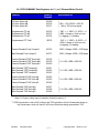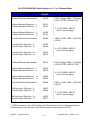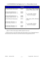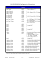
1
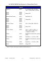
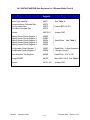
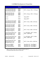
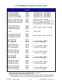
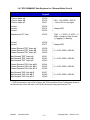
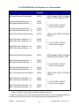
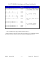
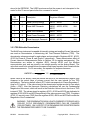
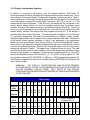
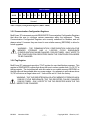
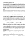
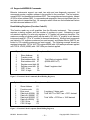
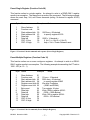
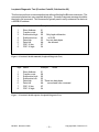
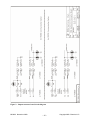
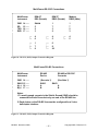
MultiComm RS-232C Connections MultiComm Instrument IBM AT DE9 (Female) IBM XT DB25 (Female) Modem DB25 (Male) GND SG TXD RXD Shield 5 2 3 1 7 3 2 1 7 2 3 14 ─── 15 ─── 16 ─── 17 ─── ┌─ └─ 4 6 ┌─ └─ 4 5 ┌─ ├─ └─ 1 7 8 ┌─ ├─ └─ 6 8 20 ┌─ └─ 4 5 Figure 10 - RS-232 (-S093) Output Connection Diagram MultiComm RS-485 Connections MultiComm Instrument RS-485 Device RS-485 to RS-232C Converter GND 14 ─── SHLD 15 ─── A(—) 16 ─── B(+) 17 ─── (See note 1) (See Note 1) SHLD SHLD A A B B Notes: 1.To avoid ground currents in the Shield, Ground (GND) should be connected to Earth Ground at only one end of the RS-485 line. 2. Each device on the RS-485 line must be configured for a 2-wire half-duplex interface. Figure 11 - RS-485 (-S103) Output Connection Diagram ML0002 November 2009 45 Copyright 2009 Bitronics LLC