1
CARLO GAVAZZI
Automation
Components
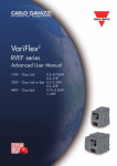
VariFlex2
RVEF series
Quick Start Guide
110V
220V
440V
Class 1ph
0.2~0.75kW
0.2~1HP
Class 1ph or 3ph 0.2~2.2kW
0.2~3HP
Class 3ph
0.75~2.2kW
1~3HP
VariFlex2 RVEF series
Quick User Guide
General Information
The manufacturer accepts no liability for any consequences resulting from inappropriate, negligent
or incorrect installation or adjustment of the optional parameters of the equipment or from
mismatching the variable speed drive with the motor.
The contents of this guide are believed to be correct at the time of printing. In the interests of
commitment to a policy of continuous development and improvement, the manufacturer reserves
the right to change the specification of the product or its performance, or the content of the guide
without notice.
All rights reserved. No parts of this guide may be reproduced or transmitted in any form or by any
means, electrical or mechanical including, photocopying, recording or by an information storage or
retrieval system, without permission in writing from the publisher.
Drive software version
This product is supplied with the latest version of user-interface and machine control software. If
this product is to be used in a new or existing system with other drives, there may be some
differences between their software and the software in this product. These differences may cause
the product to function differently. This may also apply to drives returned from the Carlo Gavazzi
Service Centre.
If there is any doubt, please contact your local Carlo Gavazzi representative or Distributor.
Environmental Statement
The electronic variable speed drives have the potential to save energy and (through increased
machine/process efficiency) reduce raw material consumption and scrap throughout their long
working lifetime. In typical applications, these positive environmental effects far outweigh the
negative impacts of product manufacture and end-of-life disposal.
Nevertheless, when the products eventually reach the end of their useful life, they can very easily be
dismantled into their major component parts for efficient recycling. Many parts snap together and
can be separated without the use of tools, while other parts are secured with conventional screws.
Virtually all parts of the product are suitable for recycling.
Product packaging is of good quality and can be re-used. All the products come in strong cardboard
cartons which themselves have a highrecycled fibre content. If not re-used, these containers can be
recycled. Polythene, used on the protective film and bags from wrapping product, can be recycled in
the same way. Carlo Gavazzi' packaging strategy favours easily recyclable materials of low
environmental impact, and regular reviews identify opportunities for improvement.
When preparing to recycle or dispose of any product or packaging, please observe local legislation
and best practice.
© Copyright - Carlo Gavazzi – All rights reserved
Revision. R03
1
VariFlex2 RVEF series
Quick User Guide
Quick Start Guide
This guide is to assist in installing and running the inverter to verify that the drive and motor
are working properly. Starting, stopping and speed control will be from the keypad. If your
application requires external control or special system programming, consult the VariFlex2
Instruction Manual (Advanced User Manual) supplied with your inverter.
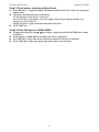
Step 1 Before starting the inverter
Please refer to chapter one (Notice for wiring) of the VariFlex2 Instruction Manual. If you feel
this was abnormal, do not start the drive until qualified personnel have corrected the situation.
(Failure to do so could result in serious injury.)
• Check inverter and motor nameplates to determine that they have the same HP and voltage
ratings. (Ensure that full load motor amps do not exceed that of the inverter.)
• Remove the terminal cover to expose the motor and power terminals.
a. Verify that AC power is wired to L1(L), L2, and L3(N) .
b. Verify that Motor leads are connected to T1, T2, and T3 .
c. IF brake module is necessary, please connect terminal voltage of the braking unit to +
and - of the inverter.
Power Indicator
Step2 Apply power to the drive.
Apply AC power to the drive and observe operator. Three 7-segment display should show
power voltage for 3~5 seconds and then show Frequency Command, factory sets 5.00.
(Frequency Command of 7-segment display should be flashed all the time.)
2
VariFlex2 RVEF series
Quick User Guide
Step3 Check motor rotation without load.
Press RUN Key. 7-segment Display will indicates 00.0to 05.0. Such value is the frequency
output value.
Check the operation direction of the motor.
IF the direction of the motor is incorrect:
Press STOP Key, turn off the AC power supply. After Power indicator LED is off,
change over theT1 and T2.
Supply the power again, then check the motor direction.
Press STOP key.
Step4 Check full speed at 50Hz/60Hz
Change the frequency with , arrow mark , please press DATA/ENTER after setting
frequency.
Set frequency to 50Hz/60Hz according to the above regulations.
Press RUN Key, inspect the motor operation as motor accelerates to full load.
Press STOP Key, inspect the motor operation as motor deceleration.
3
VariFlex2 RVEF series
Quick User Guide
CONTENTS
Quick Start Guide.........................................................................................................2
Contents .......................................................................................................................4
Introduction - Model description ................................................................................5
i.1 Model description................................................................................................. 5
i.2 Electrical Safety - general warning....................................................................... 6
i.3 System design and safety of personnel ............................................................... 6
i.4 Environmental Limits............................................................................................ 6
i.5 Access ................................................................................................................. 6
i.6 Compliance and regulations ................................................................................ 6
i.7 Motor.................................................................................................................... 6
i.8 Adjusting parameters........................................................................................... 7
i.9 Electrical installation ............................................................................................ 7
i.9.1 Electric shock risk ....................................................................................... 7
i.9.2 Isolation device ........................................................................................... 7
i.9.3 STOP function............................................................................................. 7
i.9.4 Stored charge ............................................................................................. 7
i.9.5 Equipment supplied by plug and socket...................................................... 7
i.9.6 Ground leakage current .............................................................................. 8
Chapter 1 Notice for wiring .........................................................................................9
1.1 Fuse types............................................................................................................9
1.2 Precautions for peripheral applications ..............................................................10
1.3 RVEF Wiring diagram ........................................................................................11
1.4 Descriptions of Inverter terminal.........................................................................12
1.5 Dimensions ........................................................................................................15
Chapter 2 Programming instructions & Parameter list ..........................................19
2.1 Operation Instruction of the keypad....................................................................19
2.2 Parameter function list........................................................................................20
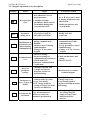
Chapter 3 Troubleshooting and maintenance ........................................................27
3.1 Trouble indication and corrective action .............................................................27
3.1.1 Fault/Error display and Diagnostics ...........................................................27
3.1.2 Set up configuration, Interface errors.........................................................30
3.1.3 Keypad operation error description ............................................................31
3.2 General functional troubleshooting ....................................................................32
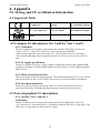
Chapter 4 Appendix UL Listing and CE certification Information .........................33
4.1 Approvals Table..................................................................................................33
4.2 Common UL information (for VariFlex2 Size 1 and 2).........................................33
4.2.1 Conformity...................................................................................................33
4.2.2 AC supply specification .............................................................................33
4.2.3 Motor overload protection..........................................................................33
4.2.4 Overspeed protection ................................................................................33
4.3 Power dependant UL information .......................................................................33
4.3.1 VariFlex2 Size 1 and Size 2 .......................................................................33
Carlo Gavazzi’s CE Declaration of Conformity ...................................................34
4
VariFlex2 RVEF series
Quick User Guide
Introduction
i.1 Model description
Inverter model
Input power
Output power
Type Selection
Series
Frame Size
AC Supply
Phase
Drive
Voltage
Rating
Drive kW Rating
Noise filter
Enclosure
RVEF A: Size1
1: 1-Phase
10: 110VAC 020: 0.20kW, 0.25 HP Nil : none
Nil: IP20
B: Size2
3: 3-Phase
20: 230VAC 040: 0.40kW, 0.50 HP F: built-in
N4:IP65 without
water and dust
proof switch
40: 400VAC 075: 0.75kW, 1.0 HP
150: 1.5kW, 2.0 HP
220: 2.2kW, 3.0 HP
5
N4S:IP65 with
water and dust
proof switch
VariFlex2 RVEF series
Quick User Guide
i.2 Electrical Safety - general warning
The voltages used in the drive can cause severe electrical shock and/or burns, and could be
lethal. Extreme care is necessary at all times when working with or adjacent to the drive.
Specific warnings are given at the relevant places in this guide.
i.3 System design and safety of personnel
The drive is intended as a component for professional incorporation into complete equipment or
system. If installed incorrectly, the drive may present a safety hazard.
The drive uses high voltages and currents, carries a high level of stored electrical energy, and is
used to control equipment which can cause injury.
System design, installation, commissioning and maintenance must be carried out by personnel
who have the necessary training and experience. They must read this safety information and this
guide carefully.
The STOP and START controls or electrical inputs of the drive must not be relied upon to
ensure safety of personnel. They do not isolate dangerous voltages from the output of the
drive or from any external option unit. The supply must be disconnected by an approved
electrical isolation device before gaining access to the electrical connections.
The drive is not intended to be used for safety-related functions.
Careful consideration must be given to the function of the drive which might result in a hazard,
either through its intended behaviour or through incorrect operation due to a fault. In any
application where a malfunction of the drive or its control system could lead to or allow damage,
loss or injury, a risk analysis must be carried out, and where necessary, further measures taken
to reduce the risk - for example, an over-speed protection device in case of failure of the speed
control, or a fail-safe mechanical brake in case of loss of motor braking.
i.4 Environmental Limits
Instructions within the supplied data and information within the VariFlex2 Advanced User
Manual regarding transport, storage, installation and the use of the drive must be complied with,
including the specified environmental limits. Drives must not be subjected to excessive physical
force.
i.5 Access
Access must be restricted to authorised personnel only. Safety regulations which apply at the
place of use must be complied with.
The IP (Ingress Protection) rating of the drive is installation dependant. For further information,
refer to the VariFlex2 Advanced User Manual.
i.6 Compliance and regulations
The installer is responsible for complying with all relevant regulations, such as national wiring
regulations, accident prevention regulations and electromagnetic compatibility (EMC)
regulations. Particular attention must be given to the cross-sectional areas of conductors, the
selection of fuses and other protection, and protective earth (ground)
connections.
The VariFlex2 Advanced User Manual contains instructions for achieving compliance with
specific EMC standards.
Within the European Union, all machinery in which this product is used must comply
with the following directives:
98/37/EC: Safety of machinery
89/336/EEC: Electromagnetic compatibility
i.7 Motor
Ensure the motor is installed in accordance with the manufacturer's recommendations.
6
VariFlex2 RVEF series
Quick User Guide
Ensure the motor shaft is not exposed. Standard squirrel cage induction motors are designed for
single speed operation. If it is intended to use the capability of a drive to run a motor at speeds
above its designed maximum, it is strongly recommended that the manufacturer is consulted
first.
Low speeds may cause the motor to overheat because the cooling fan becomes less effective.
The motor should be fitted with a protection thermistor. If necessary, an electric force vent fan
should be used. The values of the motor parameters set in the drive affect the protection of the
motor. The default values in the drive should not be relied upon. It is essential that the correct
value is entered into parameter concerning the motor rated current. This affects the thermal
protection of the motor.
i.8 Adjusting parameters
Some parameters have a profound effect on the operation of the drive. They must not be altered
without careful consideration of the impact on the controlled system. Measures must be taken to
prevent unwanted changes due to error or tampering.
i.9 Electrical installation
i.9.1 Electric shock risk
The voltages present in the following locations can cause severe electric shock and may be
lethal:
• AC supply cables and connections
• DC bus, dynamic brake cables and connections
• Output cables and connections
• Many internal parts of the drive, and external option units
Unless otherwise indicated, control terminals are single insulated and must not be touched.
i.9.2 Isolation device
The AC supply must be disconnected from the drive using an approved isolation device before
any cover is removed from the drive or before any servicing work is performed.
i.9.3 STOP function
The STOP function does not remove dangerous voltages from the drive, the motor or any
external option units.
i.9.4 Stored charge
The drive contains capacitors that remain charged to a potentially lethal voltage after the AC
supply has been disconnected. If the drive has been energised, the AC supply must be isolated
at least ten minutes before work may continue.
Normally, the capacitors are discharged by an internal resistor. Under certain, unusual fault
conditions, it is possible that the capacitors may fail to discharge, or be prevented from being
discharged by a voltage applied to the output terminals. If the drive has failed in a manner that
causes the display to go blank immediately, it is possible the capacitors
will not be discharged. In this case, consult Carlo Gavazzi or their authorised distributor.
i.9.5 Equipment supplied by plug and socket
Special attention must be given if the drive is installed in equipment which is connected to the
AC supply by a plug and socket. The AC supply terminals of the drive are connected to the
internal capacitors through rectifier diodes which are not intended to give safety isolation. If
the plug terminals can be touched when the plug is disconnected from the socket, a means of
automatically isolating the plug from the drive must be used (e.g. a latching relay).
7
VariFlex2 RVEF series
Quick User Guide
i.9.6 Ground leakage current
The drive is supplied without or with an internal EMC filter capacitor fitted. If the input
voltage to the drive is supplied through an ELCB or RCD, these may trip due to the ground
leakage current. Please refer to VariFlex2 Advanced User Manual for further information and
how to connect correctly the EMC capacitor.
8
VariFlex2 RVEF series
Quick User Guide
Chapter 1 Notice for wiring
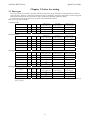
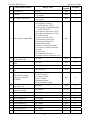
1.1 Fuse types
Drive input fuses are provided to disconnect the drive from power in the event that a component fails in the drive’s
power circuitry. The drive’s electronic protection circuitry is designed to clear drive output short circuits and ground
faults without blowing the drive input fuses. Below table shows the RVEF input fuse ratings.
To protect the inverter most effectively, use fuses with current-limit function.
RK5, CC/T type fuse for RVEF
110V class(1φ)
!
21.21 %4
" %1+,*
%4-/!
" %1+,*
$
#
#
!
21.21 %4
" %1+,*
%4-/!
" %1+,*
#
#
#
#
$
#
#
!
21.21 %4
" %1+,*
%4-/!
" %1+,*
#
#
#
#
$
#
#
!
21.21 %4
" %1+,*
%4-/!
" %1+,*
#
#
$
#
#
#
#
220V class(1φ)
220V class(3φ)
440V class(3φ)
20(/%1+,*0%/(&%0('2.-,#)20(0)-/
#+,3(/1(/0%,' #)20(0)-/
#+,3(/1(/0%,'#)-/
#+,3(/1(/0
9
VariFlex2 RVEF series
Quick User Guide
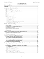
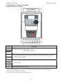
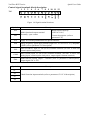
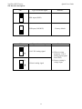
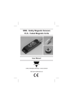
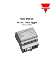
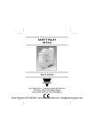
1.2 Precautions for peripheral applications:
Power
Molded-case
circuit breaker
Fuse
Leakage breaker
Magnetic
contactor
Power supply:
Make sure the correct voltage is applied to avoid damaging the
inverter.
A molded-case circuit breaker or fused disconnect must be
installed between the AC source and the inverter.
Molded-case circuit breaker:
Use a molded-case circuit breaker that conforms to the rated
voltage and current of the inverter to control the power and
protect the inverter.
Do not use the circuit breaker as the run/stop switch for the
inverter.
Fuse:
A suitable fuse should be installed with inverter rated voltage
and current when a MCCB is not being used.
AC reactor
for power
improvement
Input noise
filter
RVEF inverter
Earth Leakage circuit breaker:
Install a leakage breaker to prevent problems caused by current
leakage and to protect personnel. Select current range up to
200mA, and action time up to 0.1 second to prevent high
frequency failure.
Magnetic contactor:
Normal operations do not need a magnetic contactor. When
performing functions such as external control and auto restart
after power failure, or when using a brake controller, install a
magnetic contactor.
Do not use the magnetic contactor as the run/stop switch for the
inverter.
AC Line Reactor for power quality:
Earth Ground
Three-phase
squirrel cage
motor
Earth Ground
Figure 1-1 Typical installation
schematic
When inverters are supplied with high capacity (above
600KVA) power source, a AC reactor can be connected to
improve the PF.
Input noise filter:
A filter must be installed when there are inductive loads
affecting the inverter.
Inverter:
Output terminals T1, T2, and T3 are connected to U, V, and W
terminals of the motor. If the motor is reversed while the inverter
is set to run forward, just swap any two terminals of T1, T2, and
T3.
To avoid damaging the inverter, do not connect the input
terminals T1, T2, and T3 to AC input power.
Connect the ground terminal properly.( 230 V series: Rg
<100; 460 V series: Rg <10.)
10
VariFlex2 RVEF series
Quick User Guide
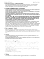
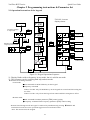
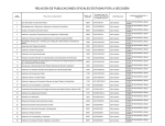
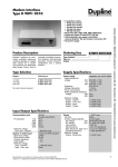
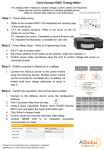
1.3RFEF Wiring diagram
Braking
Unit
Power terminal
• Single phase 100~120V
• 1/3 phase 200~240V
• 3 phase 380~480V
L1(L)
T1
L2*
T2
L3(N)
T3
PE
PE
PNP common point
(3)24V
RA(1)
(4)S1
RB(2)
Multi function digital
input
Accept DC 12/24V signal
(5)S2
NPN common point
(8)COM
Multi-function analog
input
• Set speed
• PID feed back input
(9) 10V
IM
Multi-function digital output
(6)S3
1.SW1: Digital signal selection (NPN/PNP)
2.SW2: Control signal selection
(0~10V/4~20mA) V/I
(7)S4
10k
21
(10)AIN
• Option interface
(11)COM
FM
S5
S6
(12)FM+
• T+
(2 IN/ 1 out)
• Remote keypad
T24V/0.6A
Figure 1-2 Wiring diagram
Note 1:- Connect inputs to
Terminal 3 ( internal 24vdc) for PNP mode ( Positive switching) .
Or to terminal 8 ( Common) for NPN mode( Negative switching) .
Note2:- External 24 Vdc may be used to supply the external contacts at each input
(Connect the 0V of the external supply to Common (terminal 8).)
11
VariFlex2 RVEF series
Quick User Guide
1.4 Description of Inverter Terminal
Descriptions of power terminals
Figure 1-3 Power terminals locations
Symbol
L1 ( L )
L2
Description
Main power input Single-phase: L/N*
Three-phase: L1/L2/L3
L3 ( N )
DC power and braking unit connection terminals. (match with braking units and
braking resistor to brake)
T1
T2
Inverter output
T3
PE
Grounding terminals (2 points)
* Braking units are required for applications where a load with high inertia needs to be stopped rapidly.
Use a power-matched braking unit and resistor to dissipate the energy generated by the load while stopping.
Otherwise inverter will trip on over voltage.
* Terminal at L2 will be non-functional for single-phase units.
12
VariFlex2 RVEF series
Quick User Guide
Control signal terminals block description
1 2 3 4 5 6 7 8 9 10 11 12
TM2
FM+
COM
AIN
10V
COM
S4
S3
S2
S1
24V
RB
RA
Figure 1-4 Signal terminal locations
Symbol
Description
Rated contact capacity:
RA
RB
Multi-functional output terminal
Normally open contact
(250VAC/10A)
Contact description: (refer to
parameter F21)
10V
Supply for external potentiometer for speed reference.
AIN
Analog frequency signal input terminal (high level : 8V/low level: 2V), adaptable
to PNP (refer to parameter F15 description)
24V
PNP (SOURCE) input, S1~S4 (S5/S6) common terminal, (set SW1 to PNP and
connect option card power.)
COM
NPN (SINK) input, S1~S4 (S5/S6) common terminal, (set SW1 to NPN, and
analog input, connect option card power, output signal common terminal.)
FM+
Multi-function analog output + terminal (refer to parameter F26description),
output signal: DC 0-10V.
Symbol
Description
S1
S2
S3
Multi-function input terminals (refer to parameters F11~F14 description)
S4
13
VariFlex2 RVEF series
SW function description
SW1
Quick User Guide
Type of external signal
Remarks
NPN input (SINK)
PNP input (SOURCE)
SW2
Type of external signal
V
Remarks
0~10V DC analog signal
(1) Effective when
parameter F05=2
(analog input signal
from TM2)
V
Factory default
4~20mA analog signal
14
(2) Factory setting is
voltage input
VariFlex2 RVEF series
Quick User Guide
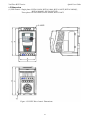
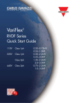
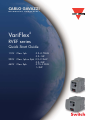
1.5 Dimension
(1) IP20 Frame1: Single phase: RVFA110020, RVFA110040, RVFA110075,RVFA120020(F),
RVFA120040(F), RVFA120075(F)
Three phase: RVFA320020, RVFA320040, RVFA320075
Figure 1-5 RVEF Drive frame1 Dimensions
15
VariFlex2 RVEF series
Quick User Guide
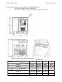
(2) IP20 Frame2: Single phase RVFB120150(F), RVFB120220(F)
Three phase RVFB320150, RVFB320220
Three phase RVFB340075(F), RVFB340150(F), RVFB120220(F)
Figure 1-6 RVEF Drive frame2 Dimensions
Unit: inch/mm
MODEL
LENGTH
A
B
Frame 1
5.2/132
4.86/123.5
2.64/67
3.03/77
Frame 2
5.2/132
4.86/123.5
4.25/108
4.65/118
E
F
G
LENGTH
MODEL
Frame 1
Frame 2
5.13/130.5 5.06/128.45
5.83/148
16
5.67/144
C
0.315/8
0.315/8
D
VariFlex2 RVEF series
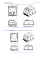
IP65 Frame1(switch) Quick User Guide
RVEFA110020N4S/RVEFA110040N4S/RVEFA110075N4S/ RVEFA120020N4S/RVEFA120040N4S/RVEFA120075N4S
8.49
8.36
7.83
4.86
6.69
7.20
5.54
5.51
Figure 1-7 RVEF Drive IP65 (switch) Frame 1 dimensions
IP65 Frame1(no switch) 8.49
8.36
7.83
RVEFA110020N4/RVEFA110040N4/RVEFA110075N4/ RVEFA120020N4/RVEFA120040N4/RVEFA120075N4
4.86
5.54
6.69
5.51
Figure 1-8 RVEF Drive IP65 (no switch) Frame 1 dimensions
17
VariFlex2 RVEF series
IP65 Frame 2 (switch):
Quick User Guide
RVEFB320150N4S/RVEFB320220N4S/RVEFB340075N4S/RVEFB340150N4S/RVEFB320220N4S
274.5
210
210
232
211.7
295
Figure 1-9 RVEF Drive IP65 (switch) Frame 2 dimensions
IP65 Frame 2 (no switch):
RVEFB320150N4/RVEFB320220N4/RVEFB340075N4/RVEFB340150N4/RVEFB320220N4
274.5
210
210
231
180.1
295
Figure 1-10 RVEF Drive IP65 (no switch) Frame 2 dimensions
18
VariFlex2 RVEF series
Quick User Guide
Chapter 2 Programming instructions & Parameter list
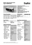
2.1 Operation Instruction of the keypad
F10=001, inverter
displays status
F
Power ON
Frequency display
in stop mode
DSP
FUN
DATA
ENT
F
RUN
STOP
RUN
STOP
DSP
FUN
Blinking output
frequency in run mode
DSP
FUN
DATA
ENT
DSP
FUN
DATA
ENT
VALUE
DSP
FUN
VALUE
Output voltage
DATA
ENT
DC voltage
VALUE
Output current
DSP
FUN
DATA
ENT
DATA
ENT
VALUE
PID Feedback
After 0.5s
DSP
FUN
DSP
FUN
Figure 2-1 Keypad Operations Sequence
*1: Display flashes with set frequency in stop mode, but it is solid in run mode.
*2: The frequency can be set during both stop and run modes.
Remote/Local change function
• Local mode
Run command via RUN/STOP key on the keypad
Frequency command
When C41=000: only UP/DOWN key on the keypad can control and F05 setting has
no effect.
When C41=001: only VR on the keypad can control and F05 setting has no effect.
• Remote mode
Run command from Run parameter (F04) control setting
Frequency command from Frequency parameter (F05) control setting
•Remote/Local change mode on keypad is achieved by simultaneously pressing /RESET and
DATA/ENT. Each successive operation toggles between local and remote.
Note: The inverter must be stopped.
19
VariFlex2 RVEF series
Quick User Guide
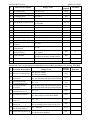
2.2 Parameter function list
Basic parameter function list
Factory
Default
Remarks
Inverter horse power
capacity
01 Acceleration time 1
02 Deceleration time 1
05.0
05.0
*1 *2
*1 *2
03
000
*1
F
Function Description
Range/ Code
00
04
05
06
07
08
09
10
00.1~999s
00.1~999s
000: Forward
Motor rotation direction
001: Reverse
000: keypad
Run command source
001: External Terminal
002: Communication Control
000: UP/Down Key on control panel
001: Potentiometer on control panel
002: AIN input signal from ( TM2)
Frequency command source 003: Multi-function input terminal
UP/DOWN function
004: RS-485 Communication
frequency setting
000: Forward/ Stop-Reverse/Stop
External control operation
001: Run/ Stop-Forward/Reverse
mode
002:3-wire—Run/ Stop
Frequency upper limit
01.0 ~200Hz
Frequency lower limit
00.0 ~200Hz
000: Decelerate to stop
Stopping method
001: Coast to stop
000: No display
Status display parameters
001: Display
11 Terminal S1 Function
12 Terminal S2 Function
13 Terminal S3 Function
14 Terminal S4 Function
15 Terminal AIN Function
000: Forward
001: Reverse
002: Preset Speed Command 1
003: Preset Speed Command 2
004: Preset Speed Command 3
005: Jog frequency Command
006: Emergency stop(E.S.)
007: Base Block (b.b.)
008: Select 2nd accel / decel time
009: Reset
010: Up command
011: Down command
012: Control signal switch
013: Communication control signal switch
014: Acceleration/deceleration prohibit
015: Master/Auxiliary speed source select
016: PID function disable
017: Analog frequency signal
input( terminal AIN)
018: PID feedback signal (terminal AIN)
019: DC Brake signal *6
000
000
000
50.0/60.0
00.0
000
000
*1
000
001
005
006
017
16 AIN signal select
000: 0~10V(0~20mA)
001: 4~20mA(2~10V)
000
17 AIN Gain (%)
000~200
100
20
*2
*2
*1
VariFlex2 RVEF series
F
Function Description
18 AIN Bias (%)
19 AIN Bias
20
21
22
23
24
25
26
27
28
29
AIN Slope Direction
Range/ Code
000~100
000: Positive
001: Negative
000: Positive
001: Negative
000: Run
001: Frequency reached
(Set frequency ± F23)
002: Frequency is within the range
set by (F22±F23)
003: Frequency Detection (>F22)
004: Frequency Detection (<F22)
005: Fault terminal
Multi-function output RY1 006: Auto reset and restart
007: Momentary power loss
008: Emergency Stop(E.S.)
009: Base Block (b.b.)
010: Motor overload protection
011: Inverter overload protection
012: retain
013: Power On
014: Communication error
015: Output current detection(>F24)
Output frequency at
00.0~200
the Set value (Hz)
Frequency detection range
00.0~30.0
(±Hz)
Output current set value
000~100%
Output current detection
00.0~25.5(Sec)
time
000: Output frequency
001: Set frequency
Multi-function output
002: Output voltage
analog type selection
003: DC voltage
(0~10Vdc)
004: Output current
005: PID feedback signal
Multi-function analog
000~200%
output gain (%)
Preset frequency 1 (Main
00.0~200Hz
frequency setting)
Preset frequency 2
00.0~200Hz
Quick User Guide
Factory
Remarks
Default
000
*1
000
*1
000
*1
000
00.0
*1
00.0
*1
000
00.0
000
*1
100
*1
05.0
*1
05.0
*1
30 Preset frequency 3
00.0~200Hz
10.0
*1
31 Preset frequency 4
00.0~200Hz
20.0
*1
32
33
34
35
36
00.0~200Hz
00.0~200Hz
00.0~200Hz
00.0~200Hz
00.0~200Hz
30.0
40.0
50.0
60.0
05.0
*1
*1
*1
*1
*1
Preset frequency 5
Preset frequency 6
Preset frequency 7
Preset frequency 8
Jog frequency instruction
21
VariFlex2 RVEF series
F
Function Description
Range/ Code
37 DC braking time
00.0~25.5 Sec
38 DC braking start frequency 01.0~10.0 Hz
39 DC braking level
000~020%
004~016
40 Carrier frequency
000: Enable
41 Auto Restart for power-loss
001: Disable
42 Auto-restart times
000~005
43 Motor rated current
44 Motor rated voltage
45 Motor rated frequency
46 Motor rated power
47 Motor rated speed
48 Torque Boost Gain (Vector)
Slip Compensation Gain
49
(Vector)
Low frequency voltage
50
compensation
Advanced parameter
51
function display
52 Factory default
53 Software version
54 Latest 3 fault records
Quick User Guide
Factory
Remarks
Default
00.5
01.5
005
010
4~16K
001 *6
000
*4
*4
*4
*4
*4
001~450
001~450
000~40
000: don’t display
001: display
010: Reset to factory default (50Hz)
020: Reset to factory default (60Hz)
CPU Version
000
*1
000
*3 *4
*3 *4
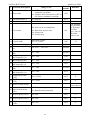
Advanced function parameter list(Enable access to these parameters by setting F51=001)
C
Function Description
00 Reverse run instruction
Acceleration stallprevention
Acceleration stall02
prevention level (%)
Deceleration stall03
prevention
Deceleration stall04
prevention level (%)
01
05 Run stall-prevention
Run stall-prevention
level (%)
Stall prevention time
07
during run
Stall prevention
08
deceleration time set
06
09 Direct start on power up
Range/ Code
000: Reverse enable
001: Reverse disable
000: Acceleration stall prevention enable
001: Acceleration stall prevention disable
Factory
default
000
000
050 - 300
200
000: Deceleration stall prevention enable
001: Deceleration stall prevention disable
000
050 - 300
200
000: Run stall prevention available
001: Run stall prevention unavailable
000
050 - 300
200
000: according to decel time set in F02
001: according to decel time set in C08
000
00.1 – 999 Sec
03.0
000: Direct start available
001: Direct start disabled
001
22
Remarks
VariFlex2 RVEF series
C
Function Description
Range/ Code
Quick User Guide
Factory
Remarks
default
11 Acceleration time 2
000: RUN instruction is OFF, Reset
command is available.
001: Whether RUN instruction is OFF or
ON, Reset command is available.
00.1~999 Sec
05.0
*1 *2
12 Deceleration time 2
00.1~999 Sec
05.0
*1 *2
This function
only available
for IP20 type,
For IP65
type , fan will
run while
power is on.
10 Reset mode
000
000: Auto-run at set temperature
13 Fan control
14 Control mode
001: Run when inverter runs
002: Always run
003: Always stop
000:Vector control
001:V/F Control
001 ~ 007
15 V/F Pattern setting
V/F base output voltage
16
198~265V / 380~530V
set
Max output frequency
17
00.2 – 200
(Hz)
Output voltage ratio at
18
00.0 – 100
max frequency (%)
19 Mid frequency(Hz)
20
21
22
23
24
Output voltage ratio at
mid frequency (%)
Min output frequency
(Hz)
Output voltage ratio at
Min frequency (%)
Torque Boost Gain
(V/F)
Slip Compensation Gain
(V/F)
001
000
*4
001/004
*8
220/440
50.0/60.0
100
00.1 – 200
25.0/30.0
00.0 – 100
50.0
00.1 – 200
00.5/00.6
00.0 – 100
01.0
00.0 ~ 30.0%
00.0
*1
00.0 ~100%
00.0
*1
Varies with
motor rating *4
25 Motor no load current
Electronic thermal relay 000: Enable motor protection
26 protection for motor
001: Disable motor protection
(OL1)
000
27 Skip frequency 1(Hz)
00.0~200
00.0
*1
28 Skip frequency 2(Hz)
00.0~200
00.0
*1
Skip frequency range
(±Hz)
00.0~30.0
00.0
*1
29
23
VariFlex2 RVEF series
C
Quick User Guide
Function Description
30 PID operation mode
31 PID Error gain
Range/ Code
000: PID Function unavailable
001: PID control, Bias D control
002: PID Control, Feedback D control
003: PID Control, Bias D reverse
characteristics control.
004: PID Control, Feedback D reverse
characteristics control.
0.00 – 10.0
Factory
default
Remarks
000
1.00
*1
01.0
10.0
0.00
*1
*1
*1
000
*1
36 PID OFFSET adjust (%) 000 – 109
000
*1
37 PID Update time (s)
PID Sleep mode
38
threshold
00.0 - 02.5
00.0
*1
00.0~200Hz
00.0
39 PID Sleep delay time
00.0~25.5
00.0
32 P: Proportional gain
0.00 – 10.0
33 I: Integral time (s)
00.0 – 100
34 D: Differential time (s) 0.00 – 10.0
35 PID OFFSET
40
41
42
43
44
000: Positive direction
001: Negative direction
000: UP/Down command is available.
Set frequency is held when inverter
stops.
001: UP/Down command is available.
Frequency Up/ Down
Set frequency resets to 0Hz when
control using MFIT
inverter stops.
002: UP/Down command is available.
Set frequency is held when inverter
stops. Up/Down is available in stop.
Local/Remote
000: UP/Down key on keypad sets
frequency
frequency control select
(Run command by the 001: Potentiometer on the keypad set
Run/Stop key)
frequency
000: Forward
001: Reverse
002: Preset Speed Command 1
003: Preset Speed Command 2
004: Preset Speed Command 3
Terminal S5 function
005: Jog Frequency Command
(option)
006: Emergency Stop(E.S.)
007: Base Block
(b.b.)
008: Select 2nd accel/decel time.
009: Reset
010: Up Command
011: Down Command
012: Control signal switch
013: Communication control signal
Terminal S6 function
switch
014: Acceleration/ deceleration disable
(option)
015: Master/auxiliary speed source select
016: PID function disable
019: DC Brake signal *7
Multi-function input
terminal S1~S6 signal 001~100
scan time (mSec 8)
24
000
000
007
009
010
VariFlex2 RVEF series
C
45
46
47
48
49
50
51
Function Description
Confirming AIN signal
001~100
scan time (mSec x 8 )
000: Run
001: Frequency reached
(Set frequency ± F23)
002: Frequency is within the range
set by (F22±F23)
003: Frequency detection (>F22)
004: Frequency detection (<F22)
005: Fault terminal
Multi-function output
006: Auto-restart
(option)
007: Momentary power loss
008: Emergency Stop(E.S. )
009: Base Block(b.b.)
010: Motor overload protection
011: Inverter overload protection
012: Reserve
013: Power ON
014: Communication error
015: Output current detection(>F24)
000: Disable (no signal loss detection)
001: Enable. On signal loss Stop
according to F09
Remote keypad control
002: Enable. Runs at the last set
selection
frequency. On signal loss
Stop is according to F04 setting or
Stop key on keypad.
000: Copy module disable
001: copy to module from inverter
Copy module
002: copy to inverter from module
003: read/ write check
Inverter communication
001 ~ 254
address
000: 4800
001: 9600
Baud rate (bps)
002: 9200
003: 38400
000: 1 Stop bit
Stop bit
001: 2 Stop bit
52 Parity bit
53 Data bits
54
Range/ Code
Communication timeout detection time
000: No parity
001: Even parity
002: Odd parity
000: 8 bits data
001: 7 bits data
(Only for Modbus ASCII Mode)
00.0 ~ 25.5 Sec
25
Quick User Guide
Factory
Remarks
default
050
005
000
Stop inverter
then connect
remote
keypad for
proper
operation *4
000
*3
001
*3 *4
003
*3 *4
000
*3 *4
000
*3 *4
000
*3 *4
00.0
*3*5
VariFlex2 RVEF series
Quick User Guide
C
Function Description
Range/ Code
55
000: Deceleration to stop.
(F02: Deceleration time 1).
Communication time- 001: Coast to stop.
out operation selection 002: Deceleration to stop.
(C12: Deceleration time 2).
003: continue operating.
Factory
default
Remarks
000
*3*5
Note: *1: Can be modified in Run mode.
*2: Frequency resolution is 1Hz for settings above 100 Hz.
*3: Cannot be modified during communication.
*4: Do not change while making factory setting.
F52 factory setting is 020(60HZ) and motor parameter value is 17.0.
F52 factory setting is 010(50HZ) and motor parameter value is 14.0.
*5: Available in Software version 1.2 or later
*6: Changed in Software version 1.5 or later
*7: Changed in Software version 1.6 or later
*8: Changed in Software version 1.7 or later
26
VariFlex2 RVEF series
Quick User Guide
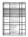
Chapter 3 Troubleshooting and maintenance
3.1 Trouble indication and corrective action
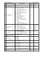
3.1.1 Fault/ Error display and Diagnostics
1. Un- reset able / un recoverable Errors
Display
Error
EPR
EEPROM
problem
Cause
EEPROM problem
Corrective Action
Change EEPROM
@
OV
@
LV
@
OH
CTR
Over voltage during Voltage
Repair or replace unit
stop
Detection circuit malfunction
Under voltage
during stop
1. Power voltage too low
2. Restraining resistor or
fuse burnt out.
3. Detection circuit
malfunctions
1. Check if the power voltage is
correct or not
2. Replace the restraining
resistor or the fuse
3. repair or replace unit
1. Thermal Detection circuit
The inverter is
1. Repair or replace unit
malfunction
overheated during
2. Improve ventilation conditions
2. Ambient temperature too
or relocate inverter
stop
high or bad ventilation
Current
transducer
detection error
Current transducer or
circuit error.
Note: “@” the Failure contact does not operate.
27
Repair or replace unit
VariFlex2 RVEF series
Quick User Guide
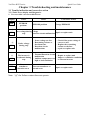
2. Errors which can be recovered both manually and automatically
Display
Error
Cause
Corrective Action
1.Motor winding and
1.Check the motor
frame short circuit
2.Check the wiring
2.Motor and ground short circuit
3.Replace the power module
3.Power module is damaged
OCS
Over current at
start
OCD
Over-current at The preset deceleration time is
deceleration too short
OCA
1. Acceleration time is too short
2. The capacity of the motor is
1. Set a longer acceleration time
higher than the capacity of the 2. Replace the inverter with the
inverter
same or greater capacity as
Over-current at
3.Short circuit between the motor that of the motor
acceleration
winding and frame.
3. Check the motor
4.Short circuit between motor 4. Check the wiring
wiring and earth
5. Replace the IGBT module
5. IGBT module is damaged
OCC
OVC
OHC
COT
Over-current 1. Transient load change
during run 2. Transient power change
Set a longer deceleration time
Increase inverter capacity
1. Set a longer deceleration time
Over voltage
2. Add a braking resistor or
1. Deceleration time setting is too
during
braking unit
short or excessive load inertia
operation/
3. Add a reactor at the input
2. Power voltage varies widely
deceleration
line side
4. Increase inverter capacity
1. Check if there are any
problems with the load
High heat sink 1. Heavy load
2. Increase inverter capacity
temperature 2. Ambient temperature too high
3. Improve ventilation
during
or bad ventilation
conditions
operation
4. Inspect the setting value of
parameter C13
1. Increase C54
1. C54 communication time-out
communication time-out
detection time is too short.
detection time.
Communication 2. Inverter communication is
2. Keep the inverter
broke.
time-out
communication.
detection
3. Inverter can not receive the
3. Check the received Modbus
correct Modbus data within
data is correct from Master.
detection time.
28
VariFlex2 RVEF series
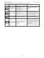
3. Errors which can only be recovered manually (no auto-restart)
Display
Error
OC
Over-current
during stop
OL1
OL2
LVC
Motor overload
Cause
1. OC Detection circuit
malfunction
2. Bad connection for CT
signal cable
Quick User Guide
Corrective Action
Send the inverter back for
repair
1. Increase motor capacity
1. Heavy load
2. Improper settings of F43
2. Set F43 correctly according
to motor nameplate.
Inverter overload Excessively Heavy load
Increase inverter capacity
1. Power voltage too low
Under voltage
2. Power voltage varies
during operation
widely
1. Improve power quality.
2. Set a longer acceleration time
3. Add a reactor at the power
input side
4. Contact technical support
29
VariFlex2 RVEF series
Quick User Guide
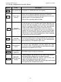
3.1.2 Set up Configuration, Interface Errors.
Display
SP0
SP1
Error
Description
Zero speed stop Set frequency is <0.1Hz Increase set frequency
Fail to start
directly
1. If the inverter is set to external control mode (F04=001), and
direct start is disabled (C09=001), the inverter cannot be
started and will flash STP1 when the Run switch is ON when
applying power (see descriptions of C09).
2. Direct start is possible when C09=000.
1. If the inverter is set to external control mode (F04=001), the
inverter will stop according to the setting of F9 when the
stop key is pressed. STP2 flashes after stop. Turn the Run
switch to OFF and then ON again to restart the inverter.
SP2
E.S.
Keypad
emergency stop 2. If the inverter is in communication mode and Stop key is
enabled, the inverter will stop in the way set by F9 when
Stop key is pressed during operation and then flashes STP2.
The PC has to send a Stop command then a Run command
to the inverter for it to be restarted.
The inverter will decelerate to stop and flashes E.S. when there
External
is an external emergency stop signal via the multi-function
emergency stop
input terminals(see descriptions of F11~F14).
b.b.
External base
block
The inverter stops immediately and then flashes b.b. when
external base block is input through the multi-functional input
terminal (see descriptions of F11~F14).
PID
PID feedback
signal loss
PID feedback signal circuit error detection
1. When REMOTE KEYPAD does not connect with inverter,
this signal will be displayed on the Remote keypad.
REMOTE
2. When REMOTE KEYPAD connects with inverter, this
KEYPAD cable
signal will be displayed on the main keypad.
broken
3. When both REMOTE KEYPAD and main KEYPAD display
this signal means communication errors.
30
VariFlex2 RVEF series
Quick User Guide
3.1.3 Keypad operation error description
Display
Error
Cause
1. Attempt to Press or keys when F05> 0 or in
speed operation.
Er2
Er5
Er6
Er7
EP1
EP2
Key operation 2. Attempt to modify
error
parameters, which can not
be modified during Run
(see parameter list).
Parameter
setting error
1. F07 is within ranges of
C27±C29or C28±C29
2. F07<F08 or F07=F08
1.Issue a control command
during communication
Modification of
disabled
parameter is not
2. Modify C49~C53 during
allowed during
communication.
communication
3. Change C47 by remote
keypad.
Corrective Action
1. or keys can be used
to modify frequencies only
when F05=0.
2. Modify parameters only
in stop mode.
1. Modify F32~F33
2. 3-00>3-01
1. Issue the enabling
command before while
communicating.
2. Set up parameters before
communicating.
3. Change C47 by inverter
keypad.
1. Incorrect wiring.
2. Incorrect settings of
1. Check the hardware and
Communication
communication parameters.
wiring.
error
3. Check-sum error.
2. Check C49~C53
4. Incorrect communication
verification.
Incorrect
parameter
settings
1. Attempt to modify F00
2. Voltage and current
detection circuits are
malfunctioning.
1. Set C48=1.2, can not
connect with Copy Unit.
Parameter set 2. Copy Unit failure.
error, Copy Unit 3. The voltage and drive
failure
rating on Copy Unit & the
inverter are different.
Copy the parameter to
Parameters do
inverter to verify the
not match
parameter not matched.
31
Reset inverter or contact
technical support
1.Modify C48
2. Change Copy Unit
3. Copy from keypad to
inverter with only matched
HP ratings
1. Change Copy Unit
2. The voltage and HP
rating of Copy Unit is
different than the
inverter.
VariFlex2 RVEF series
Quick User Guide
3.2 General functional troubleshooting
Status
Checking point
Corrective Action
Is power applied to L1, L2, and L3(N)
terminals (is the charging indicator lit)?
Is the power applied?
Turn the power OFF and then ON
again.
Make sure the input line voltage is
correct.
Make sure all terminal screws are
secured firmly.
Are there voltage outputs on T1, T2, and
T3 terminals?
Motor does not
run
Is the motor mechanically overloaded?
Turn the power OFF and then ON
again.
Reduce the load to improve
performance.
Are there any problems with the inverter?
See error descriptions to check wiring
and correct if necessary.
Has the forward or reverse run
commands been issued?
Is analog frequency input signal
wiring correct?
Is frequency input voltage correct?
Configure operations through the
Is operation mode setting correct?
digital panel
Are wiring for output terminals T1, T2, Wiring must match U, V, and W
Motor rotates in
and T3 correct?
terminals of the motor.
the wrong
Are wiring for forward and reverse
Check wiring and correct if
direction
signals correct?
necessary.
Motor rotates Are wiring for output terminals T1, T2, Check wiring and correct if
and T3 correct?
necessary.
in the wrong
direction
Is the setting of frequency command Check the operation mode setting
on the keypad.
The motor
source correct?
speed can not
Reduce the applied load.
vary
Is the load too large?
Is there an analog input signal?
Is the setting of operation mode correct?
Confirm the motor’s specifications.
Confirm the gear ratio.
Motor running Is the load too large?
at too high or
Are specifications of the motor (poles, Confirm the highest output
too low speeds.
voltage…) correct?
frequency.
Reduce the load.
Minimize the variation of the load.
Is the setting of the highest output
Increase capacities of the inverter
frequency correct?
and the motor.
Motor speed is
Add an AC reactor at the power
incorrect or
input side if using single-phase
erratic
Is the load too large?
power.
Check wiring if using three-phase
power.
Is the gear ratio correct?
32
VariFlex2 RVEF series
Quick User Guide
4. Appendix
UL Listing and CE certification Information
4.1 Approvals Table
CE approval
Europe
See attached certificate
UL / cULs approval
USA & Canada
File number E319186
RoHS
-
-
4.2 Common UL information (for VariFlex2 Size 1 and 2)
4.2.1 Conformity
The drive conforms to UL listing requirements only when the following are observed:
• Class 1 60/75°C (140/167°F) copper wire only is used in the installation
• The ambient temperature does not exceed 40°C (104°F) when the drive is operating
• The terminal tightening torques specified in section 4.1 Power terminal connections are
used
4.2.2 AC supply specification
The drive is suitable for use in a circuit capable of delivering not more than 100,000 RMS
symmetrical Amperes at 264Vac RMS maximum (200V drives) or 528Vac RMS maximum
(400V drives).
4.2.3 Motor overload protection
The drive provides motor overload protection. The overload protection level is 150% of fullload current. Refer to the VariFlex2 RVEF Advanced User Guide for further information.
4.2.4 Overspeed protection
The drive provides overspeed protection. However, it does not provide the level of
protection afforded by an independent high integrity overspeed protection device.
4.3 Power dependant UL information
4.3.1 VariFlex2 Size 1 and Size 2
Conformity
The drive conforms to UL listing requirements only when the following is observed:
• UL listed class CC fast acting fuses e.g. Bussman Limitron KTK series, Gould Amp- Trap
ATM series or equivalent are used in the AC supply.
33
VariFlex2 RVEF series
Quick User Guide
34
OUR SALES NETWORK IN EUROPE
FRANCE - Carlo Gavazzi Sarl
Zac de Paris Nord II, 69, rue de la Belle
Etoile, F-95956 Roissy CDG Cedex
Tel: +33 1 49 38 98 60
Fax: +33 1 48 63 27 43
[email protected]
AUSTRIA - Carlo Gavazzi GmbH
Ketzergasse 374, A-1230 Wien
Tel: +43 1 888 4112
Fax: +43 1 889 10 53
[email protected]
BELGIUM - Carlo Gavazzi NV/SA
Schaarbeeklei 213/3, B-1800 Vilvoorde
Tel: +32 2 257 4120
Fax: +32 2 257 41 25
[email protected]
DENMARK - Carlo Gavazzi Handel A/S
Over Hadstenvej 40, DK-8370 Hadsten
Tel: +45 89 60 6100
Fax: +45 86 98 15 30
[email protected]
FINLAND - Carlo Gavazzi OY AB
Petaksentie 2-4, FI-00661 Helsinki
Tel: +358 9 756 2000
Fax: +358 9 756 20010
[email protected]
GERMANY - Carlo Gavazzi GmbH
Pfnorstr. 10-14
D-64293 Darmstadt
Tel: +49 6151 81000
Fax: +49 6151 81 00 40
[email protected]
GREAT BRITAIN - Carlo Gavazzi UK Ltd
7 Springlakes Industrial Estate,
Deadbrook Lane, Hants GU12 4UH,
GB-Aldershot
Tel: +44 1 252 339600
Fax: +44 1 252 326 799
[email protected]
ITALY - Carlo Gavazzi SpA
Via Milano 13, I-20020 Lainate
Tel: +39 02 931 761
Fax: +39 02 931 763 01
[email protected]
NETHERLANDS - Carlo Gavazzi BV
Wijkermeerweg 23,
NL-1948 NT Beverwijk
Tel: +31 251 22 9345
Fax: +31 251 22 60 55
[email protected]
NORWAY - Carlo Gavazzi AS
Melkeveien 13, N-3919 Porsgrunn
Tel: +47 35 93 0800
Fax: +47 35 93 08 01
[email protected]
PORTUGAL - Carlo Gavazzi Lda
Rua dos Jerónimos 38-B,
P-1400-212 Lisboa
Tel: +351 21 361 7060
Fax: +351 21 362 13 73
[email protected]
SPAIN - Carlo Gavazzi SA
Avda. Iparraguirre, 80-82,
E-48940 Leioa (Bizkaia)
Tel: +34 94 480 4037
Fax: +34 94 480 10 61
[email protected]
SWEDEN - Carlo Gavazzi AB
V:a Kyrkogatan 1,
S-652 24 Karlstad
Tel: +46 54 85 1125
Fax: +46 54 85 11 77
[email protected]
SWITZERLAND - Carlo Gavazzi AG
Verkauf Schweiz/Vente Suisse
Sumpfstrasse 32,
CH-632 Steinhausen
Tel: +41 41 747 4535
Fax: +41 41 740 45 40
[email protected]
OUR SALES NETWORK IN NORTH AMERICA
CANADA - Carlo Gavazzi Inc.
2660 Meadowvale Boulevard,
CDN-Mississauga Ontario L5N 6M6,
Tel: +1 905 542 0979
Fax: +1 905 542 22 48
[email protected]
USA - Carlo Gavazzi Inc.
750 Hastings Lane,
USA-Buffalo Grove, IL 60089,
Tel: +1 847 465 6100
Fax: +1 847 465 7373
[email protected]
MEXICO - Carlo Gavazzi Mexico S.A. de
C.V.
Calle La Montaña no. 28, Fracc. Los Pastores
Naucalpan de Juárez, EDOMEX CP 53340
Tel & Fax: +52.55.5373.7042
[email protected]
SINGAPORE - Carlo Gavazzi Automation
Singapore Pte. Ltd.
61 Tai Seng Avenue #05-06
UE Print Media Hub
Singapore 534167
Tel: +65 67 466 990
Fax: +65 67 461 980
MALAYSIA - Carlo Gavazzi Automation
(M) SDN. BHD.
D12-06-G, Block D12,
Pusat Perdagangan Dana 1,
Jalan PJU 1A/46, 47301 Petaling Jaya,
Selangor, Malaysia.
Tel: +60 3 7842 7299
Fax: +60 3 7842 7399
CHINA - Carlo Gavazzi Automation
(China) Co. Ltd.
Rm. 2308 - 2310, 23/F.,
News Building, Block 1,
1002 Shennan Zhong Road,
Shenzhen, China
Tel: +86 755 83699500
Fax: +86 755 83699300
HONG KONG - Carlo Gavazzi
Automation Hong Kong Ltd.
Unit 3 12/F Crown Industrial Bldg.,
106 How Ming St., Kowloon,
Hong Kong
Tel: +852 23041228
Fax: +852 23443689
Carlo Gavazzi Ltd
Zejtun - MALTA
Carlo Gavazzi Controls SpA
Belluno - ITALY
Uab Carlo Gavazzi Industri Kaunas
Kaunas - LITHUANIA
OUR PRODUCTION SITES
Carlo Gavazzi Industri A/S
Hadsten - DENMARK
MAN QUICK RVEF ENG - REV.0 08/10
Carlo Gavazzi Automation
(Kunshan) Co., Ltd.
Kunshan - CHINA
HEADQUARTERS
Carlo Gavazzi Automation SpA
Via Milano, 13 - I-20020
Lainate (MI) - ITALY
Tel: +39 02 931 761
[email protected]
CARLO GAVAZZI
Automation
Specifications are subject to change without notice. Pictures are just an example.
OUR SALES NETWORK IN ASIA AND PACIFIC
Components
Further information on
www.gavazziautomation.com - www.carlogavazzi.com