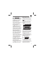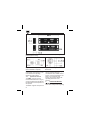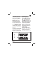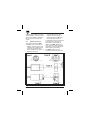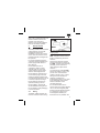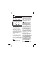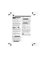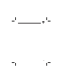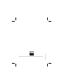
1
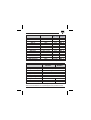
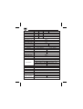
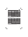
SMS.. Safety Magnetic Sensors
CLS.. Coded Magnetic Units
User Manual
CARLO GAVAZZI CONTROLS - Sensors Division
http://www.carlogavazzi.com
Table of Contents
1. INTRODUCTION..........................................................................3
2. MOUNTING AND MECHANICAL DIMENSIONS.........................3
2.1 Parallelepiped sensors .........................................................3
2.2 Cylindrical sensors ...............................................................4
3. OPERATING MODES..................................................................4
3.1 Parallelepiped sensors .........................................................5
3.2 Cylindrical sensors ...............................................................6
4. INSTALLATION............................................................................7
4.1 Warnings ..............................................................................7
4.2 Wiring ...................................................................................7
5. MAINTENANCE ...........................................................................8
6. TECHNICAL DATA ....................................................................10
1.
INTRODUCTION
This user manual must be read
and understood completely, prior
to carrying out any operation on
the SMS../CLS.. sensors, by
personnel dealing with all the
activities of the sensors.
All the operations described in this
manual must be carried out
exclusively by specialized
personnel carefully following all
the indications given.
The SMS.. safety sensors are
suited for gate/door monitoring
applications whose safety
category (according to EN 954-1)
can reach level 4. The sensors
and the coded magnetic units
CLS.. are only a subset of the
safety-related parts of the
machine: the safety level of the
entire system - according to EN
954-1 - depends also on all the
other safety components and
devices of the system set.
The sensors have onboard N.O.
and/or N.C. safety and/or warning
contacts, operated when the
corresponding CLS.. magnetic
unit is close to the sensor.
All the SMS..- CLS.. pairs
described in this manual make up
a multiple flow redundant coded
system that meets the
requirements of the EN 1088
harmonized standard. The design
of the SMS.. sensors and of the
CLS.. magnetic units result in
SMS../CLS pairs which cannot be
easily operated by readily
available instruments, increasing
the safety level of the application.
NOTE.
The meanings of “Normally Open”
and “Normally Closed” contact
throughout this manual are the
following:
ü N.O.: open contact with SMS..
sensor not operated, therefore
without the operating magnetic
unit (CLS.. far from SMS..),
ü N.C.: closed contact with
sensor not operated, therefore
without the operating magnetic
unit (CLS.. far from SMS..).
The user is responsible for the
risks evaluation of the safety
system; he decides with complete
responsibility that the products
described in the user manual are
suitable for his application.
The SMS../CLS.. sensors do not
require internal maintenance: if
they are tampered with they loose
their safety functions and the
guarantee is annulled.
2.
MOUNTING AND
MECHANICAL
DIMENSIONS
2.1
Parallelepiped sensors
The SMS../CLS.. pairs (see the
mechanical dimensions in Fig. 1)
can be mounted using the slots on
both sides of the enclosure,
suitable for M4 screws. It is
3
Fig. 1: Mechanical dimensions of the sensors and the operating units
parallelepiped housing.
Fig. 2: Dim. of std cylindrical SMS
(other available on request)
recommended to use brass or
nonmagnetic steel screws, so as
not to reduce the operating
distances of the sensors.
2.2
Cylindrical sensors
The SMS.. sensors (see the
mechanical dimensions in Fig. 2)
can be mounted using the M18x1
threaded part and the special nut,
24 spanner.
The CLS.. magnetic unit (see the
4
Fig. 3: CLS-A2 magnetic unit
dimensions
mechanical dimensions in Fig. 3)
can be mounted using the
countersunk hole, suitable for M4
screws. It is recommended to use
brass or nonmagnetic steel
screws, so as not to reduce the
operating distances of the
sensors.
OPERATING MODES
3.
An SMS.. sensor is ”operated”
when all its safety and/or signaling
contacts have changed their
open/close condition when the
CLS.. magnetic unit is close to the
sensor (see Technical Data for
operating distances).
The coded structure of the
SMS../CLS.. pairs requires, in
order to operate correctly the
sensors, that the magnetic units
are brought closer to the sensors
following a defined alignment with
them.
3.1
Parallelepiped sensors
The CLS.. unit must be brought
closer to the SMS.. sensors so
that the printed arrows are faced
(see Fig. 4).
The alignment is achieved moving
the CLS.. unit towards the SMS..
sensor along the X axis (side
alignment, e.g. sliding door) or Y
axis (frontal alignment e.g. hinged
gate/door or slide) or
perpendicularly to the XY plane (Z
axis, e.g. hinged gate/door).
A correct positioning is achieved
when the SMS.. sensor and the
CLS.. unit lie on the same XY
plane, aligned to the same
position X0. In that position, if the
distance between the sensor and
the magnetic unit is less than the
Operating Distance (D-ON, see
Technical Data), the sensor is
correctly operated.
Different alignments can lead to
wrong operating conditions (e.g.
none or only one internal contact
changes its status).
Starting from SMS.. correctly
operated by the CLS.. unit as
stated before, and Y distance null,
the sensor can be properly
operated also with the magnetic
unit misaligned along the X axis or
Z axis up to a maximum position
Fig. 4 - Operating and alignment direction of the parallelepiped
sensors.
5
of X0 ± n mm or Z0 ± n mm (see
Technical Data), if the XY plane in
which lies the CLS.. is parallel to
the XY plane in which lies the
sensor.
3.2
Cylindrical sensors
The alignment between SMS..
and CLS.. must be carried out:
• radially, centering sensor and
magnetic unit so that the axes
of the two cylindrical cases
match (see A Axis in Figure 5),
• angularly, facing the
corresponding sensor and
magnetic unit arrow lines, so
that the printed lines B and C
are parallel (see Figure 5).
The operation must be carried out
by bringing the magnetic unit
closer to the sensor axially or
radially. The SMS../CLS.. axes
must coincide for axial operating
movement or must be parallel for
radial operating movement.
The SMS.. sensors can be
properly operated also when the
Fig. 5: Cylindrical sensors alignment and operation
6
CLS.. unit is misaligned (with null
distance between sensor and
magnetic unit) along the r
direction (see Technical Data) if
their axis are always parallel.
INSTALLATION
4.
4.1
Warnings
The safety sensor and the relative
coded magnetic unit must be
installed according to the
standards in force in the country
of use, when the machine is not
powered and with no dangers for
the operator.
It is recommended to keep the
connection cables separate from
power supply loads cables of
other devices.
Ensure that there are no
conductors, cables or loose
materials that can come into
contact with the sensor and/or
with the coded magnetic unit.
Ensure that the conductors are
not excessively tight, that their
positioning avoids potential cuts
or squashing and that they are not
in the way of people or things.
Ensure that the machine can
operate according to all the
technical data in this manual.
Avoid installation during storms.
Do not dispose of the packaging
in the environment.
4.2
Wiring
The CLS.. coded magnetic unit
must be mounted on the moving
Fig. 6: Example of application on
hinged guard
guard of the machine, and the
SMS.. magnetic sensor must be
fixed on a stationary part of the
machine.
All the screw and nuts must be
properly clamped; the position of
the SMS.. sensors must avoid any
possibility for the operator to
reach dangerous parts of the
machine.
The connections of all the SMS..
sensors are listed in Table 1; the
pin-out of the connectorized
models is shown in Fig. 7 and 8.
Fitting the sensor and/or the
magnetic unit directly on
ferromagnetic parts (or very close
to ferromagnetic parts), would
lead to a reduction of the
operating distances.
It is recommended to fit the
sensor and/or the coded magnetic
unit on non ferromagnetic parts.
If fitted on ferromagnetic material,
it is necessary to place a non
ferromagnetic material (min.
thickness of 6 mm) between the
7
Fig. 7: Pin-out of female
connectors
Fig. 8: Pin-out of male connectors
SMS../CLS.. pair and the
ferromagnetic parts of the
machine closest to them.
To avoid mutual interactions
between different magnetic
sensors, when using more than
one pair of SMS../CLS.. on the
same application, every pair of
sensor-magnet must be placed at
least 50 mm far from the adjacent
sensor-magnet pair in any
direction.
At the end of the installation, the
machine installation procedure
must be carried out to check for
correct wiring and in particular to
check that the machine stop time
is less than the operator access to
the machine time, once the guard
is open.
NOTE.
The SMS../LD models make
available a signaling LED in series
to the N.C. contact: this contact is
8
not voltage free, but is polarized;
it needs and forces a voltage drop
when not operated. If the wires
are connected with the wrong
polarity, the LED is permanently
OFF (however the sensor still
works properly).
NOTE.
The EN 1088 standard states
that the magnetic type of
protection devices associated
to the guard cannot be easily
eluded through the use of
easily available instruments or
objects such as screws, nails,
pieces of metal, keys and
generally through objects or
tools related to the normal
machine working operations.
Based on the indication of the
standard, a multiple flow coded
magnet, such as the SMS..+
CLS.. systems, is a device that
is difficult to elude.
Nevertheless, due to the
impossibility of guaranteeing
non elusion through any
substituted magnetic actuator
for the coded magnetic unit, the
machine manufacturer must
carry out an installation that
includes mechanical obstacles
which do not allow the insertion
of a substitution actuator in
front of the sensor (with the
guard open).
MAINTENANCE
5.
The integrity of the SMS../CLS..
sensors and of all the parts
connected to them must be
checked regularly. The frequency
SENSOR
CABLE
SMS-01, SMS-02, 4x0.15 mm2
cable
SMS-A2P-02
SMS-02/LD
4x0.15 mm2
cable
SMS-02/S1
4x0.15 mm2
cable
SMS-03
4x0.15 mm2
cable
SMS-03+
CM-1A4..
CM-1A4
SMS-03/NC
4x0.15 mm2
cable
2x0.35 mm2
cable
CM-1A4
SMS-03/NC/S1
CF-1A4
SMS-10/NC
4x0.15 mm2
cable
SMS-A2P-10
SMS-10
2x0.35 mm2
cable
SMS-A2P-30
4x0.15 mm2
SMS-A2P-30/S2
cable
(*)
of the inspections is part of the
machine risks evaluation and it is
under the complete responsibility
CONNECTIONS
BLUE - BLACK : N.O.
WHITE - BROWN : N.C.
BLUE - BLACK : N.O.
WHITE - BROWN : N.C.
(BROWN: LED anode)
BLUE - BLACK : N.O .(39 Ohm series)
WHITE - BROWN : N.C.
BLUE - BLACK : N.O.
WHITE - BROWN : N.O.
Pin 1 - Pin 2: N.O. (Fig. 8)
Pin 3 - Pin 4: N.O. (Fig. 8)
BLUE - BLACK : N.O.
WHITE - BROWN : N.O.
BLUE - YELLOW : N.C.
(not for safety functions)
Pin 1 - Pin 2: N.O. (Fig. 8)
Pin 3 - Pin 4: N.O. (Fig. 8)
Pin 1 - Pin 3: N.C. (Fig. 7)
(not for safety functions)
BLUE - BLACK : N.O.
WHITE - BROWN : N.C.
(not for safety functions)
BLUE - BLACK : N.O.
BLUE(*)– BLACK : N.O.
WHITE – BROWN(*) : N.O.
The BLUE and BROWN conductors are short-circuited
Table 1: SMS.. sensors output features.
9
of the person in charge of such
evaluations.
Operator safety can be
compromised by the lack of
regular inspections or
maintenance, or if they are carried
out incorrectly, or by non
specialized personnel, or at lower
intervals than prescribed.
Regular inspections consist of
carrying out an inspection of the
wiring, of the installation, of the
tightening and of the integrity of
the SMS../CLS.. pair, and in
repeating - for each sensor /
magnetic unit pair - all the
operations concerning the
machine start-up procedure.
Maintenance consists of a regular
cleaning of the sensor and the
magnetic unit and of all the
connected devices: dust and other
substances must be removed
from the devices and it must be
dried of liquids or any
condensation. All cleaning
operations must be carried out
whilst the machine is rigorously
not powered.
TECHNICAL DATA
6.
All the distances involved are
referred to a sample CLS.. device,
with SMS../CLS.. pairs mounted
far away from other magnetic
parts or devices, and with SMS..
frontally operated (see Fig. 4).
The Operating Distance (D-ON)
is the one in which all safety
10
contacts have switched their
status.
The Release Distance (D-OFF) is
the one in which, when the
magnetic unit moves away from
the sensor, one contact releases
returning to the rest position, while
the other (if any) is still switched.
The Reset distance (D-RESET)
is the one in which, when the
magnetic unit moves away from
the sensor, all safety contacts
have released and return to the
rest position.
The letters V, I, P, refer to the
Voltage, Current, Power that
characterizes the output contacts
of the sensors.
In Table 2 is summarized for each
SMS.. model the corresponding
CLS.. actuating magnet and the
maximum safety category of the
whole safety-related part of the
machine in which the sensor /
magnet pair can be employed.
NOTE.
The technical data of this manual
are applicable also to the SMS..
models with different cable length.
Associated Usage
Magn. Unit category
SMS-01
1 N.O. + 1 N.C.
CLS
Max. 4
SMS-02
1 N.O. + 1 N.C.
CLS
Max. 4
SMS-03
2 N.O.
CLS
Max. 4
SMS-10
1 N.O.
CLS
Max. 2
SMS-03/NC
2 N.O. + 1 N.C. aux.
CLS
Max. 4
SMS-10/NC
1 N.O. + 1 N.C. aux.
CLS
Max. 2
SMS-03 + CM-1A4/..MT
2 N.O.
CLS
Max. 4
SMS-03/NC/S1
2 N.O. + 1 N.C. aux.
CLS
Max. 4
SMS-02/S1
1 N.O. + 1 N.C.
CLS
Max. 4
SMS-02/LD
1 N.O. + 1 N.C.
CLS
Max. 4
SMS-A2P-02
1 N.O. + 1 N.C.
CLS-A2
Max. 4
SMS-A2P-10
1 N.O.
CLS-A2
Max. 2
SMS-A2P-30
2 N.O.
CLS-A2
Max. 3
SMS-A2P-30/S2
2 N.O.
CLS-A2
Max. 3
Model
Output contacts
Table 2: Summary of the main features of the SMS.. safety sensors.
PARAMETERS
PARALLELEPIPED CYLINDRICAL
MODELS
MODELS
Housing material
ABS NOVODUR L3FR PBT + 30% glass
Housing flammability class
V0 (UL 94)
Shock resistance
30 g / 11 ms
Vibration resistance
10 - 55 Hz
Degree of protection
IP67
Operating temperature
[-25 ÷ 75] °C
Operating / storage humidity
5 ÷ 95 %
Misalignment SMS../CLS
Max ± 4 mm
Max ± 2 mm
Weight
Ca. 70 g
Ca. 60 g
External Dimensions (mm)
25 x 88 x 13
(M18x1) x 38 (1)
(1)
The SMS-A2P-30/S2 dimensions are (M18x1) x 50 mm
Table 3: General features for all parallelepiped and cylindrical models
11
PARAMETERS
Function
D-ON (mm)
D-OFF (mm)
D-RESET (mm)
Switching V max
Switching I max
Switching P max
Max continuous I
Connection
SMS-01 SMS-02 SMS-03 SMS-03 + CM-1A4
1 N.O. + 1 N.C.
2 N.O.
10 ± 3
20 ± 3
20 ± 3
15 ± 3
30 ± 5
22 ± 3
20 ± 3
35 ± 5
22 ± 3
100 Vac
0.25 A
5 VA
1.0 A
4x0.15 mm2 PVC cable, 2m Cn. M12 TPU 4-pin
PARAMETERS
Function
D-ON (mm)
D-OFF (mm)
D-RESET (mm)
Switching V max
Switching I max
Switching P max
Max continuous I
SMS-03/NC and SMS-03/NC/S1
1 N.C. (Signal)
2 N.O. (Safety)
17 ± 5
20 ± 3
21 ± 5
22 ± 5
21 ± 5
22 ± 5
100 Vac
0.25 A
5 VA
1.0 A
SMS-03/NC: PVC cable, 2m
4x0.15 mm2
2x0.35 mm2
SMS-03/NC/S1: M12 TPU Connector, 0.3m
CF-1A4 type
CM-1A4 type
Connection
PARAMETERS
Function
LED Colour
LED ON
LED Anode
LED Cathode
Voltage Drop
(N.C. closed)
Max continuous I
12
SMS-02/LD
See SMS-02
RED
N.C. Contact Closed
BROWN wire (BRN)
WHITE wire (WHI)
BRN - WHI (LED ON)
WHI - BRN (LED OFF)
1.2 ÷ 3.2 V
0.3 ÷ 0.9 V
0.7 A
PARAMETERS
SMS-02/S1
Function
1 N.O. + 1 N.C.
D-ON (mm)
D-OFF (mm)
D-RESET (mm)
20 ± 3
30 ± 5
35 ± 5
N.O.
N.C.
100 Vac 100 Vac
0.25 A 0.25 A
5 VA
5 VA
0.2 A (1) 1.0 A
Switching V max
Switching I max
Switching P max
Max continuous I
Connection
(1)
(2)
(1)
(2)
SMS-10/NC
1 N.O.(2) 1 N.C.
(Safety) (Signal)
20 ± 3 17 ± 5
22 ± 3 21 ± 5
22 ± 3 21 ± 5
SMS-10
1 N.O.
20 ± 3
22 ± 5
22 ± 5
100 Vac
0.25 A
5 VA
1.0 A
PVC cable, 2m
2x0.35 mm2
4x0.15 mm2
Due to a 39 Ohm, 2 W series-connected resistor.
Two N.O. series-connected contacts
PARAMETERS
SMS-A2P- 02
SMS-A2P-10
Function
D-ON (mm)
D-OFF (mm)
D-RESET (mm)
Switching V max
Switching I max
Switching P max
Max continuous I
1 N.O. + 1 N.C.
15 ± 4
20 ± 6
25 ± 7
Connection
4x0.15 mm2
1 N.O. (1)
16 ± 4
20 ± 6
20 ± 6
100 Vac
0.25 A
5 VA
1.0 A
PVC cable, 2m
2x0.35 mm2
SMS-A2P-30
SMS-A2P-30/S2
2 N.O.(2)
16 ± 4
20 ± 6
20 ± 6
4x0.15 mm2
Multiple flux coded.
The BROWN and WHITE wires are short-circuited
13
14
15
Mod. 3249/B1 - IV/06
SAIET reserves the right to make improvements or changes without prior notice.