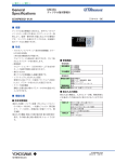
1
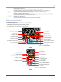
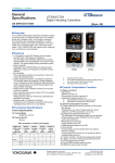
General
Specifications
UP35A/UP32A
Program Controller
l
tiona
Func ment
nce
Enha
GS 05P02D41-01EN
nOverview
The UP35A/UP32A program controller employs an
easy-to-read, 14-segment large color LCD display,
along with navigation keys, thus greatly increasing
the monitoring and operating capabilities. A ladder
sequence function is included as standard. The short
depth of the controller helps save instrument panel
space. The UP35A also support open networks such
as Ethernet communication.
nFeatures
• A 14-segment, active (PV display color changing
function) color LCD display is employed.
Two five-digit, high-resolution displays are possible.
Alphabet letters can be displayed in an easy-to-read
manner.
The guide display shows parameter names.
• Easy to operate
Navigation keys (SET/ENTER and Up/Down/Left/Right
arrow keys) are employed to facilitate making settings.
• 65 mm depth
The small depth enables the mounting in a thin and
small instrumented panel.
• Ladder sequence function is included as standard.
This function allows for creating a simple sequence
control. Dedicated LL50A Parameter Setting Software
(sold separately) allows for performing programming
using a ladder language.
• Various built-in open network functions such as
Ethernet are available.
Easy connection with various vendors’ PLCs is
possible.
(UP32A support CC-Link and RS485 communication
only.)
• Quick setting function
Setting only the minimum necessary parameters for
operation is possible. (For single-loop control only)
• Equipped with a multitude of functions
Universal I/O and eight control modes (cascade control,
etc) are included as standard. PID control, heating/
cooling control, feed forward control, etc. are available.
• LL50A Parameter Setting Software (sold separately)
The parameters and ladder programs of UTAdvanced
digital indicating controller can be built from a PC
using this software. It makes data management even
easier.
• Dust-proof and drip-proof
IP66 (for front panel) (Not applicable to side-by-side
close mounting.)
NEMA4 (Hose-down test only)
UP35A
the operator can switch between them according to
the operating status. Each program pattern consists
of multiple line segments (program segments). The
operator sets the time interval of each program
segment using the segment time or slope. The
operator can also set such instructions as the number
of repeats, start/stop, and status output (event
output) for a given program pattern.
Number of Program
pattern
Number of program
segment per pattern
Number of program
pattern
Segment time
Number of PV event
PV event type
Number of Time event
Time of time event
Number of
repeat cycles
Wait operation
Fast-forwarding of
program operation
nFunctional Specifications
Synchronized
program operation
Program Pattern Functions
Program pattern link
The program setting function increases or decreases
the value of a target setpoint (SP) according to a
given program pattern that varies with time. The
controller stores two or more program patterns and
UP32A
Program pattern edit
Max. 2 (Max. 4 with option)
Max. 20
Max. 20
Max. 40 with option
(sum of program pattern for all program patterns)
0.00 to 999.59 (hour.minute or minute.second)
2
PV (measured value) high/low limit
SP (setpoint) high/low limit
Deviation high/low limit
Deviation high and low limits
Deviation within high and low limits
Target SP high/low limit
Target SP deviation high/low limit
Target SP deviation high and low limits
Target SP deviation within high and low limits
Control output high/low limit alarm
Cooling control output high/low limit alarm
4
0.01 to 999.59 (hour.minute or minute.second)
0 to 999, CONT (limitless number of times)
1 group
1: Normal, 2: Twice, 5: Five times, 10: Ten
times, 20: Twenty times
Use this function when checking the
program pattern setting. Only Time of
Segment and Time event can be faster.
If the progress of the operation of one unit is
faster, the program operation can be forcibly
stopped by digital input when switching
between segments.
Available
Addition and deleting of program segment
can be available. Copy and deletion of
program pattern can also be available.
Yokogawa Electric Corporation
2-9-32, Nakacho, Musashino-shi, Tokyo, 180-8750 Japan
Tel.: 81-422-52-7179 Fax.: 81-422-52-6619
GS 05P02D41-01EN
©Copyright Aug. 2010
6th Edition Mar.31,2015
2
nControl Computation Function
High/low output limiter
Control Specifications
Tight shut function
(1) Control Mode
Single-loop control.
(2) Control period
200 ms
Model and
Number
suffix code
of analog
(See the
input
model code)
points
UP35A
-x0x
1
-x1x
1
UP32A
-x0x
1
-x2x
1
*1: *2:
Rate-of-change limiter of
output
Output dead band
Number
of analog
output
points (*1)
Number Number of
of contact
contact
input
output
points
points (*2)
1
1
3
8
3
8
1
1
3
5
3
5
Excluding control output
Excluding control output relays
Control Computation Specifications
(1) Combination of types of control and control
modes
• PID control
• ON/OFF control
• Heating and cooling control
(2) Control Computation Function
(a) The number of PID parameter groups
Four sets of PID parameters can be set.
(b) Selecting the PID parameter group
The following PID parameter groups can be selected.
• Segment PID
• Measured input zone PID
• Target setpoint zone PID
• Reached target setpoint zone PID
• Local PID
• Reference deviation
(c) Auto-tuning
• Tuning results can be selected from two options,
Normal or Stable.
• Tuning output limit can be set. (It cannot be used in
heating/cooling control.)
(d) “Super” function: Overshoot-suppressing function
(e) “Super 2” function: Hunting-suppressing function
(f) RESET preset output function
(g) Input ERROR preset output function
(h) MANUAL preset output function
(3) Operation Mode Switching
Operation
mode
switching
Start of program operation (PROG)
Stop of program operation (RESET)
Start of local-mode operation (LOCAL)
Start of remote-mode operation (REM)
Pause/cancel release of program operation (HOLD)
Advance of segment (ADV)
Automatic (AUTO)/Manual (MAN) switching
Integral time
0.1 to 999.9%
1 to 6000 sec. or OFF (using manual
reset)
1 to 6000 sec. or OFF
0.1 to 100.0%/sec., OFF
For heating and cooling control:
-100.0 to 50.0%
For position proportional control: 1.0
to 10.0%
Alarm Functions
• Types of Alarm
Measured value
alarm
Deviation alarm
Rate-of-change
alarm
Setpoint alarm
Output alarm
Other alarms
PV (measured value) high/low limit alarm
Deviation high/low limit alarm
Deviation high and low limits alarm
Deviation within high and low limits alarm
Analog input PV high/low limit alarm
Auxiliary analog input high/low limit alarm
Feedback input high/low limit alarm
PV rate-of-change alarm
SP (setpoint) high/low limit alarm
Target SP high/low limit alarm
Target SP deviation high/low limit alarm
Target SP deviation high and low limits alarm
Target SP deviation within high and low limits alarm
Control output high/low limit alarm
Cooling control output high/low limit alarm
Heater disconnection alarm (for /HA option)
Self-diagnosis alarm
FAIL
• Alarm Functions
Alarm output action
Number of alarm settings
Number of alarm output points
Alarm stand-by action
Alarm latch (forced reset) function
Alarm hysteresis
Alarm ON/OFF delay timer
2
Max. 2
Contact I/O Function
This function allows for allocating the input error
condition, operation condition, alarm condition or other
conditions to the contact input and contact output.
Contact
input
(4) Control Parameter Setting Range
Proportional band
-5.0 to 105.0%
Low limit setpoint < high limit setpoint
When manual control is carried out
with 4 to 20 mA output, control output
can be reduced to about 0 mA.
Contact
output
Switch to PROG (Start of program operation)
Switch to RESET (Stop of program operation)
Program pattern 1 to 4 selection and starting the
program operation simultaneously
Switch to LOCAL(LSP) (Start of local-mode operation)
PROG/RESET Switch
PROG/LOCAL(LSP) Switch
PROG/HOLD Switch
Switch to HOLD (Start of hold-mode operation)
Advance of segment
Wait ON/OFF switch
AUTO/MAN switch
Auto-tuning START/STOP switch
Latch release
LCD backlight ON/OFF switch
PV red/white switch
Message interrupt displays 1 through 4
Program pattern number selection
PID number selection
Manual preset output number selection
PV event, Time event, Alarm
Status output
Derivative time
ON/OFF control hysteresis
0.0 to 100.0% of measured input
(one
range width
or two hysteresis points)
-5.0 to 105.0% (however, 0 mA or less
Preset output value
cannot be output)
All Rights Reserved. Copyright © 2010-2015, Yokogawa Electric Corporation
GS 05P02D41-01EN
Mar.31,2015-00
3
Ladder Sequence Function
(3) Sequence Device
(1) Number of I/O Points
Number of digital input points
Number of digital output points
UP35A
Up to 8
Up to 8
Digital I/O
UP32A
Up to 5
Up to 5
Internal device
This is limited by the number of contact I/O signal
points. (See the model code.)
(2) Types of Instruction
Number of
instructions
Number of basic
instruction types
13
Number of
application
instruction types
73
Special device
Types of device
Input relay
Output relay
M relay (bit data)
DAT register (data)
P register (parameter)
K register (constant)
Special relay (bit data)
Number of points
8 (max)
8 (max)
256
28
10
30
12
Process data and process relay can be used
besides the above-mentioned.
(4) Program capacity
Max. Program capacity: 300 steps *
Remark
Load, AND, OR, Timer,
Counter, etc.
Comparison, reverse,
addition/subtraction/
multiplication/division, logic
operation, high/low limiter, etc.
*: Available number of steps differs according to the
parameters, using command and control period.
(5) Ladder computation period
Ladder computation period is the same as control
period.
Communication Function
Function
Modbus/TCP
Modbus
(RTU/ASCII)
PROFIBUS-DP
CC-Link
A standard industry
protocol allowing
communications
between the controller
and devices such as
PCs, PLCs, and DCSs.
Used for communication
between PLCs and
remote I/O, enabling
highspeed data
transmission.
DeviceNet
Peer to peer
Coordinated
Communication
PC link
Ladder
A protocol allowing
multiple controllers to
send and receive data
between one another. The
Ladder Program is used.
A protocol to coordinate
the operation of two
or more instruments
controlling the same
process.
The proprietary Yokogawa
protocol allowing
communications to PCs,
PLCs and touch panels.
A protocol to
communicate to PLCs.
Method
Interface
Server
Gateway
Ethernet
Ethernet
+ RS-485
Slave
RS-485
Slave
RS-485
Modbus
master
function
Slave
RS-485
Modbus
master
function
Slave
Modbus
master
function
Multi-drop
RS-485
RS-485
RS-485
RS-485
RS-485
(2 wire
only)
Targets
PLC and others
RS-485: UT75A/UT55A/
UT52A/UT35A/UT32A/
UP55A/UP35A/UM33A (*1)
PLC and others, UT75A/
UT55A/UT52A/UT35A/
UT32A/UP55A/UP35A/
UP32A/UM33A (*1)
PLC and others
UT75A/UT55A/UT52A/
UT35A/UT32A/UP55A/
UP35A
PLC and others
UT75A/UT55A/UT52A/
UT35A/UT32A/UP55A/
UP35A/UP32A/UM33A
PLC and others
UT75A/UT55A/UT52A/
UT35A/UT32A/UP55A/
UP35A
UT75A/UT55A/UT52A/
UT35A/UT32A/UP55A/
UP35A/UP32A
Max connection
2 connections
31 units
Communication
Data
PV, ALM etc
31 units
Number of nodes:
126
31 Units
(Main Controller is
included.)
Number of nodes: 42
(Remote device)
31 Units
(Main Controller is
included.)
Number of nodes: 64
31 Units
(Main Controller is
included.)
Read/Write: 4 units
Read only : 28 units
Master/
Slave
RS-485
UT75A/UT55A/UT52A/
UT35A/UT32A/UP55A/
UP35A/UP32A (*2)
Master : 1 unit
Slave : 31 units
Slave
RS-485
UT75A/UT55A/UT52A/
UT35A/UT32A/UP55A/
UP35A/UP32A/UM33A (*2)
31 units
*1: UT digital indicating controller, Signal conditioner JUXTA, Power monitor POWERCERT can be connected.
*2: UT digital indication controllers can be connected.
Physical Interface
Ethernet
Standard : IEEE802.3 (10BASE-T, 100BASE-TX)
Max segment length : 100 m
Max. Connecting Configuration : Cascade Max. 4 level (10BASE-T), Max. 2 level (100BASE-TX)
RS-485
Standard: EIA RS-485
Communication method: Two-wire harf-duplex or four-wire harf-duplex, start-stop synchronization, and
non-procedural
Baud rate: 600,1200,2400,4800,9600,19200 or 38400 bps (*3)
Peer to peer communication is fixed at 19200 bps
Maximum communication distance: 1200 m
Terminating resistor: 220Ω (External)
*3: “38400 bps” is available only for UP35A (Type 3 code = 1)
All Rights Reserved. Copyright © 2010-2015, Yokogawa Electric Corporation
GS 05P02D41-01EN
Mar.31,2015-00
4
PROFIBUS-DP Standard : Field bus (IEC61158)
Corresponding version : DP V0
Baud rate : 9.6k, 19.2k, 45.45k, 93.75k, 187.5k, 0.5M, 1.5M, 3M, 6M, 12M, AUTO (*4)
Communication distance : 1200 m (9.6k to 93.75k), 1000m (187.5k), 400m (0.5M), 200m (1.5M), 100m (3M to 12M)
*4: AUTO automatically sets the baud rate to that of the host controller (PROFIBUS-DP master).
CC-Link
Supported version : Remote device (Ver.1.10, Ver.2.00)
Baud rate : 156k, 625k, 2.5M, 5M, 10M bps
Transmission distance : 1.2km (156k bps), 600m (625k bps), 200m (2.5M bps), 150m (5M bps), 100m (10M bps)
When using optical repeater : 7.6 km (156k) to 4.3 km (10M)
DeviceNet
Standard : Field bus (IEC61158)
Baud rate 125k, 250k, 500k bps
Transmission distance 500m (125k bps), 250m (250k bps), 100m (500k bps)
nHardware Specifications
Display Specifications
•PV display: 5-digit, 14-segment active color LCD (white/red)
Character height; UP35A: 21.5 mm, UP32A: 13.0 mm
•Data display: 5-digit, 11-segment color LCD (orange)
•Bar graph display: 12-segment color LCD (orange)
(9) Deviation indicator
(1) PV display
(2) Group display
(Pattern number)
(4) Data display
(3) Symbol display
(10) Status indicator
(5) Bar-graph display
(Event, alarm)
(6) Event indicator
(11) Security indicator
(12) Ladder operation indicator
(7) Key navigation indicator
(13) Loop 2 indicator
(8) Parameter display level
indicator
(2) + (3) + (4) : Setpoint display
UP35A
(1) PV display
(2) Group display
(Pattern number)
(11) Ladder operation indicator
(3) Symbol display
(4) Data display
(9) Status indicator
(5) Bar-graph display
(Event, alarm)
(6) Event indicator
(10) Security indicator
(7) Key navigation indicator
(8) Parameter display level
indicator
(2) + (3) + (4) : Setpoint display
UP32A
All Rights Reserved. Copyright © 2010-2015, Yokogawa Electric Corporation
GS 05P02D41-01EN
Mar.31,2015-00
5
Names of Operation Parts
(1) DISPLAY key
(4) Light-loader interface
(2) PARAMETER key
(3) SET/ENTER key
Up/Down/Left/Right arrow keys
(5) User function keys
UP35A
(1) DISP key
(4) Light-loader interface
(2) PARA key
(3) SET/ENTER key
Up/Down/Left/Right arrow keys
(5) User function keys
UP32A
All Rights Reserved. Copyright © 2010-2015, Yokogawa Electric Corporation
GS 05P02D41-01EN
Mar.31,2015-00
6
Universal Input Specifications
•Number of inputs: 1
•Input type, instrument range, and measurement accuracy: See the table below.
Input Type
Instrument Range (°C)
-270.0
to 1370.0°C
-270.0
to 1000.0°C
-270.0
to 500.0°C
-200.0
to 1200.0°C
-270.0
to 400.0°C
0.0
to 400.0°C
Instrument Range (°F)
-450.0
to
2500.0°F
-450.0
to
2300.0°F
-200.0
to
1000.0°F
-300.0
to
2300.0°F
-450.0
to
750.0°F
-200.0
to
750.0°F
B
0.0
to
1800.0°C
32
to
3300°F
S
R
0.0
0.0
to
to
1700.0°C
1700.0°C
32
32
to
to
3100°F
3100°F
N
-200.0
to
1300.0°C
-300.0
to
2400.0°F
E
L
W
Platinel 2
-270.0
-200.0
-200.0
0.0
0.0
0.0
to
to
to
to
to
to
1000.0°C
900.0°C
400.0°C
400.0°C
2300.0°C
1390.0°C
-450.0
-300.0
-300.0
-200.0
32
32.0
to
to
to
to
to
to
1800.0°F
1600.0°F
750.0°F
1000.0°F
4200°F
2500.0°F
PR20-40
0.0
to
1900.0°C
32
to
3400°F
0.0
to
2000.0°C
K
J
T
Thermocouple
U
W97Re3W75Re25
JPt100
RTD
Pt100
Standard signal
DC voltage/current
-200.0
to 500.0°C
-150.00
to 150.00°C
-200.0
to 850.0°C
-200.0
to 500.0°C
-150.00
to 150.00°C
0.400 to 2.000 V
1.000 to 5.000 V
4.00 to 20.00 mA
0.000 to 2.000 V
0.00 to 10.00 V
0.00 to 20.00 mA
-10.00 to 20.00 mV
0.0 to 100.0 mV
Accuracy
±0.1% of instrument range ±1 digit for 0°C or more
±0.2% of instrument range ±1 digit for less than 0°C
±2% of instrument range ±1 digit for less than -200.0°C
of thermocouple K
±1% of instrument range ±1 digit for less than -200.0°C
of thermocouple T
±0.15% of instrument range ±1 digit for 400°C or more
±5% of instrument range ±1 digit for less than
400°C
±0.15% of instrument range ±1 digit
±0.1% of instrument range ±1 digit
±0.25% of instrument range ±1 digit for less than 0°C
±0.1% of instrument range ±1 digit for 0°C or more
±0.2% of instrument range ±1 digit for less than 0°C
±1.5% of instrument range ±1 digit for less than 200.0°C of thermocouple E.
±0.2% of instrument range ±1 digit (Note 2)
±0.1% of instrument range ±1 digit
±0.5% of instrument range ±1 digit for 800°C or more
Accuracy is not guaranteed for less than 800°C.
32
to
3600°F
±0.2% of instrument range ±1 digit
-300.0
-200.0
-300.0
-300.0
-200.0
to
to
to
to
to
1000.0°F
300.0°F
1560.0°F
1000.0°F
300.0°F
±0.1% of instrument range ±1 digit (Note 1)
±0.1% of instrument range ±1 digit
±0.1% of instrument range ±1 digit (Note 1)
±0.1% of instrument range ±1 digit
±0.1% of instrument range ±1 digit
The accuracy is that in the standard operating conditions: 23±2°C, 55±10%RH, and power frequency at 50/60 Hz.
Note 1: ±0.3°C ±1 digit in the range between 0 and 100°C, ±0.5°C ±1 digit in the range between -100 and 200°C.
Note 2: W: W-5% Re/W-26% Re(Hoskins Mfg.Co.). ASTM E988
• Input sampling (control) period: 200 ms
• Burnout detection:
Functions at TC, RTD, and standard signal.
Upscale, downscale, and off can be specified.
For standard signal, burnout is determined to have
occurred if it is 0.1 V or 0.4 mA or less.
• Input bias current: 0.05 µA (for TC or RTD)
• Measured current (RTD): About 0.16 mA
• Input resistance:
TC or mV input: 1 MΩ or more
V input: About 1 MΩ
mA input: About 250 Ω
• Allowable signal source resistance:
TC or mV input: 250 Ω or less
Effects of signal source resistance: 0.1 µV/Ω or less
DC voltage input: 2 kΩ or less
Effects of signal source resistance: About 0.01%/100 Ω
•Allowable wiring resistance:
RTD input: Max. 150 Ω/wire (The conductor
resistance between the three wires shall be equal.)
Wiring resistance effect: ±0.1ºC/10 Ω
•Allowable input voltage/current:
TC, mV, mA and RTD input: ±10 V DC
V input: ±20 V DC
mA input: ±40 mA
•Noise rejection ratio:
Normal mode: 40 dB or more (at 50/60 Hz)
Common mode: 120 dB or more (at 50/60 Hz)
For 100-240 V AC, the power frequency can be set
manually.
All Rights Reserved. Copyright © 2010-2015, Yokogawa Electric Corporation
Automatic detection is also available.
For 24 V AC/DC, the power frequency can be set
manually.
•Reference junction compensation error:
±1.0ºC (15 to 35ºC)
±1.5ºC (-10 to 15ºC and 35 to 50ºC)
•Applicable standards: JIS/IEC/DIN (ITS-90) for TC
and RTD
Contact Input Specifications
•Number of inputs: See the table of Model and Suffix
Codes.
•Input type: No-voltage contact input or transistor
contact input
•Input contact rating: 12 V DC, 10 mA or more
Use a contact with a minimum on-current of 1 mA or
more.
•ON/OFF detection:
No-voltage contact input:
Contact resistance of 1 kΩ or less is determined as
“ON” and contact resistance of 50 kΩ or more as
“OFF.”
Transistor contact input:
Input voltage of 2 V or less is determined as “ON”
and leakage current must not exceed 100 µA when
“OFF.”
•Minimum status detection hold time: Control period
+50 ms
•Use: PTNO. switch, operation mode switch, and
event input
GS 05P02D41-01EN
Mar.31,2015-00
7
Analog Output Specifications
•Number of outputs:
Control output: 1
Cooling-side control output of Heating/cooling type: 1
•Output type: Current output or voltage pulse output
•Current output: 4 to 20 mA DC or 0 to 20 mA DC/load
resistance of 600 Ω or less
•Current output accuracy: ±0.1% of span (±5% of
span for 1 mA or less)
The accuracy is that in the standard operating
conditions: 23±2°C, 55±10%RH, and power
frequency at 50/60 Hz.
•Voltage pulse output:
Use: Time proportional output
On-voltage: 12 V or more/load resistance of 600 Ω or
more
Off-voltage: 0.1 V DC or less
Time resolution: 10 ms or 0.1% of output, whichever
is larger
Retransmission Output Specifications
•Number of outputs: Retransmission output; 1, shared
with 15 V DC loop power supply or Cooling-side
control output.
•Current output: 4 to 20 mA DC or 0 to 20 mA DC/
load resistance of 600 Ω or less
•Current output accuracy (conversion accuracy from
PV display on the set scale): ±0.1% of span (±5% of
span for 1 mA or less)
The accuracy is that in the standard operating
conditions: 23±2°C, 55±10%RH, and power
frequency at 50/60 Hz.
This is not conversion accuracy through input
and output but the performance of transmission
output itself.
15 V DC Loop Power Supply Specifications
(Shared with retransmission output or Cooling-side
control output.)
•Power supply: 14.5 to 18.0 V DC
•Maximum supply current: About 21 mA (with shortcircuit current limiting circuit)
Step Response Time Specifications
Within 1 s
(63% of analog output response time when a step
change of 10 to 90% of input span is applied)
Relay Contact Output Specifications
•Contact type and number of outputs:
Control output: contact point 1c; 1 point
Cooling-side control output of Heating/cooling type:
contact point 1c; 1 point
Event output: contact point 1a; 3 points (common is
independent)
•Contact rating:
Contact point 1c (control output): 250 V AC, 3 A or 30
V DC, 3A (resistance load)
Contact point 1a (control output): 240 V AC, 3 A or 30
V DC, 3 A (resistance load)
Contact point 1a (alarm output): 240 V AC, 1A or 30
V DC, 1 A (resistance load)
•Use: Time proportional output, event output, alarm
output, FAIL output, etc.
All Rights Reserved. Copyright © 2010-2015, Yokogawa Electric Corporation
•Time resolution of control output: 10 ms or 0.1% of
output, whichever is larger
*:
The control output should always be used with a
load of 10 mA or more.
The event output should always be used with a
load of 1 mA or more.
Transistor Contact Output Specifications
•Number of outputs: See the table of Model and Suffix
Codes.
•Output type: Open collector (SINK current)
•Output contact rating: Max. 24 V DC, 50 mA
•Output time resolution: Min. 200 ms
•Use: Event output, alarm output, FAIL output, etc.
Position Proportional Output Specifications
•Position signal input:
Slide resistance: 100 Ω to 2.5 kΩ of total resistance
100% side and slide line: with disconnection
detection
0% side: without disconnection detection
Current input: 4 to 20 mA (with disconnection detection)
Input resistance: about 330 Ω
•Sampling period: 50 ms
•Measurement resolution: 0.1% of input span
•Position proportional relay output:
UP35A: Contact point 1a; 2 points, 250 V AC, 3 A or
30 V DC, 3 A (resistance load)
UP32A: Contact point 1a; 2 points, 240 V AC, 3 A or
30 V DC, 3 A (resistance load)
Note: This should always be used with a load of 10 mA
or more.
Heater Break Alarm Specifications
•Number of inputs: 2
•Number of outputs: 2 (transistor contact output)
•Use: Measures the heater current using an external
current transformer (CT) and generates a heater
break alarm when the measured value is less than
the break detection value.
•Current transformer input resistance: About 9.4 Ω
•Current transformer input range: 0.0 to 0.1 Arms
(0.12 Arms or more cannot be applied.)
•Heater current setting range: OFF, 0.1 to 300.0 Arms
Heater current measured value display range: 0.0 to
360.0 Arms
Note: The CT ratio can be set. CT ratio setting range: 1
to 3300
•Recommended CT: CT from U.R.D., Ltd.
CTL-6-S-H: CT ratio 800, measurable current range:
0.1 to 80.0 Arms
CTL-12L-30: CT ratio 3000, measurable current
range: 0.1 to 180.0 Arms
•Heater current measurement period: 200 ms
•Heater current measurement accuracy: ±5% of
current transformer input range span ± 1digit (CT
error is not included.)
•Heater current detection resolution: Within 1/250 of
current transformer input range span
•Break detection On-time: Min. 0.2 second (for time
proportional output)
GS 05P02D41-01EN
Mar.31,2015-00
8
Safety and EMC Standards
•Safety:
Compliant with IEC/EN61010-1 (CE), IEC/EN610102-030 (CE), approved by CAN/CSA C22.2 No.
61010-1 (CSA), approved by UL61010-1.
Installation category: II
Pollution degree: 2
Measurement category: I (CAT I) (UL, CSA)
O (Other) (CE)
Rated measurement input voltage: Max. 10 V DC
Rated transient overvoltage: 1500 V (*)
*:
This is a reference safety standard value for
measurement category I of IEC/EN/CSA/UL610101. This value is not necessarily a guarantee of
instrument performance.
•EMC standards:
Compliant with
CE marking
EN 61326-1 Class A, Table 2 (For use in industrial
locations),
EN 61326-2-3
*:
The instrument continues to operate at a
measurement accuracy of within ±20% of the
range during testing.
EN 55011 Class A, Group 1
EN 61000-3-2 Class A
EN 61000-3-3
EMC Regulatory Arrangement in Australia and New Zealand
EN 55011 Class A, Group 1
•KC marking: Electromagnetic wave interference
prevention standard, electromagnetic wave protection
standard compliance
Construction, Installation, and Wiring
•Dust-proof and drip-proof: IP66 (for front panel) (Not
available for side-by-side close mounting)/NEMA4 *
*:
Hose-down test only
•Material: Polycarbonate (Flame retardancy: UL94V-0)
•Case color: White (Light gray) or Black (Light
charcoal gray)
•Weight: 0.5 kg or less
•External dimensions (mm):
UP35A: 96 (W) × 96 (H) × 65 (depth from the panel
face)
UP32A: 48 (W) × 96 (H) × 65 (depth from the panel
face)
(Depth except the projection on the rear panel)
•Installation: Direct panel mounting; mounting bracket,
one each for upper and lower mounting
•Panel cutout dimensions (mm):
UP35A: 92+0.8/0 (W) × 92+0.8/0 (H)
UP32A: 45+0.6/0 (W) × 92+0.8/0 (H)
•Mounting attitude: Up to 30 degrees above the
horizontal. No downward titling allowed.
•Wiring: M3 screw terminal with square washer (for
signal wiring and power wiring)
Power Supply Specifications and Isolation
•Power supply:
Rated voltage: 100-240 V AC (+10%/-15%), 50/60 Hz
24 V AC/DC (+10%/-15%) (for /DC option)
•Power consumption:
UP35A: 18 VA (DC: 9 VA, AC: 14 VA if /DC option is
specified)
UP32A: 15 VA (DC: 7 VA, AC: 11 VA if /DC option is
specified)
•Data backup: Nonvolatile memory
•Power holdup time: 20 ms (for 100 V AC drive)
All Rights Reserved. Copyright © 2010-2015, Yokogawa Electric Corporation
•Withstanding voltage
Between primary terminals and secondary terminals:
2300 V AC for 1 minute (UL, CSA)
Between primary terminals and secondary terminals:
3000 V AC for 1 minute (CE)
Between primary terminals: 1500 V AC for 1 minute
Between secondary terminals: 500 V AC for 1 minute
*: (Primary terminals: Power* and relay output
terminals; Secondary terminals: Analog I/O signal
terminals, contact input terminals, communication
terminals and functional grounding terminals.)
Power terminals for 24V AC/DC models are the
secondary terminals.
•Insulation resistance: Between power supply
terminals and a grounding terminal 20 MΩ or more at
500 V DC
•Isolation specifications
PV (universal ) input terminals
Control, retransmission (analog) output terminals
(not isolated between the analog output terminals)
Valve position (feedback) input terminals
Control relay (contact point c/contact point a x 2) output terminals
PV event-1 relay (contact point a) output terminals
PV event-2 relay (contact point a) output terminals
Time event-1 relay (contact point a) output terminals
Position proportional relay output terminals
Internal Power
circuits supply
Contact input terminals (all)
RS-485 communication terminals
24 V DC loop power supply terminals
Contact output (transistor) terminals
Ethernet communication terminal
PROFIBUS-DP/DeviceNet/CC-Link communication terminals
Current transformer input terminals
The circuits divided by lines are insulated mutually.
Environmental Conditions
Normal Operating Conditions:
•Ambient temperature: -10 to 50ºC (side-by-side close
mounting: -10 to 40 ºC)
If the CC-Link option is specified, 0 to 50 °C for
UP35A; 0 to 40 °C for UP32A.
(side-by-side mounting: 0 to 40 °C for UP35A/UP32A
with CC-Link option)
•Ambient humidity: 20 to 90% RH (no condensation
allowed)
•Magnetic field: 400 A/m or less
•Continuous vibration at 5 to 9 Hz: Half amplitude of
1.5 mm or less, 1oct/min for 90 minutes each in the
three axis directions
Continuous vibration at 9 to 150 Hz: 4.9 m/s2 or
less, 1oct/min for 90 minutes each in the three axis
directions
•Short-period vibration: 14.7 m/s2, 15 seconds or less
•Shock: 98 m/s2 or less, 11 ms
•Altitude: 2000 m or less above sea level
•Warm-up time: 30 minutes or more after the power is
turned on
•Startup time: Within 10 seconds
*: The LCD (a liquid crystal display) is used for a
display portion of this product. The LCD has a
characteristic that the display action becomes
late at the low temperature. However, the control
function is not affected.
GS 05P02D41-01EN
Mar.31,2015-00
9
Transportation and Storage Conditions:
•Temperature: -25 to 70ºC
•Temperature change rate: 20ºC/h or less
•Humidity: 5 to 95% RH (no condensation allowed)
Effects of Operating Conditions
•Effect of ambient temperature:
Voltage or TC input: ±1 µV/ºC or ±0.01% of F.S./ºC,
whichever is larger
Current input: ±0.01% of F.S./ºC
RTD input: ±0.05ºC/ºC (ambient temperature) or less
Analog output: ±0.02% of F.S./ºC or less
•Effect of power supply voltage fluctuation
Analog input: ±0.05% of F.S. or less
Analog output: ±0.05% of F.S. or less
(Each within rated voltage range)
All Rights Reserved. Copyright © 2010-2015, Yokogawa Electric Corporation
GS 05P02D41-01EN
Mar.31,2015-00
10
nBlock Diagram
Equipped as standard
DI41 to DI45 are equipped when optional suffix code /X4.
PV input
Contact inputs
RS-485, Ethernet, PROFIBUS-DP, DeviceNet, CC-Link
Input type
IN
Input unit
UNIT
Input range/scale
RH, RL
Analog input bias
A.BS
Analog input filter
A.FL
SDP
Start of program operation
when DI changes from OFF to ON.
Com.
SH, SL
DI2
DI3
DI41
DI42
Start of local-mode operation
when DI changes from OFF to ON.
DI1
Stop of program operation
when DI changes from OFF to ON.
PV
DI43
DI44
DI45
Program pattern
selection
(Select a
number during a
RESET state.)
Input ladder calculation program (signal goes to the control computation as is when without ladder program). For ladder program, see the LL50A Parameters Setting Software User’s Manual.
PV input bias
BS
PV input filter
FL
LSP
L.PID
Reset
RST
Program pattern
LOC
TSP
TIME
RUN
SP limiter
PV display
PTNO.
Local target setpoint
S.PID
TM.RT
SPH, SPL
SP display
Control computation
CNT
Input error preset output
Output limiter
EPO
When sensor burnout occurs
Manual preset output
ALG
OH, OL
Normal
MPON
Manual operation
Output limiter
OH, OL
OLMT
MAN
AUTO
A/M
Preset output
PO
RST
RESET
RUN
RUN
LOC
RESET/RUN switch
Output terminal assignment
OT
* After the control output terminal is specified by the parameter OT,
other current output terminals can be used as retransmission output.
OUT retransmission output
O1RS
DO11 to DO15 are equipped
when optional suffix code /Y1.
Equipped as standard
PV event, Time event, Alarm
RET retransmission output
RTS
Output ladder calculation program (signal goes to the output as is when without ladder program). For ladder program, see the LL50A Parameter Setting Software User’s Manual.
For optional suffix code /HA
HAL1
HAL2
OUT
Heater break
alarm 1
Heater break
alarm 2
Relay
OUT
RET
Current or voltage pulse
AL1
AL2
AL3
DO11
DO12
DO13
Time event 4
Time event 3
Time event 2
Alarm 2
Alarm 1
Time event 1
PV event 2
PV event 1
Heater break alarm
DO14
DO15
Current
(Current when retransmission output)
Legend
All Rights Reserved. Copyright © 2010-2015, Yokogawa Electric Corporation
Terminal
Parameter
Function
Analog signal
Contact signal
Front panel key
GS 05P02D41-01EN
Mar.31,2015-00
11
nTerminal Arrangement
Terminal Arrangement for UP35A Single Loop Control
Control output
Relay contact output
NC
101
NO
102
COM
103
OUT
(Suffix code: Type1=-0)
Terminal wiring differs in Heating/cooling
control and Position proportional control.
Refer to the terminals of Position
proportional control output and
Heating/cooling control output below.
Factory default: Control output is relay.
Factory default: PV input
type is undefined.
PV
TC input
RTD input
A 201
+ 202
Current (mA) input Voltage (mV, V) input
Heating/cooling control output
Heating/cooling relay contact output (Suffix code: Type 1=-2)
+ 202
+ 204
- 203
E4-terminal area
OUT2
Cooling NO
-side
101
OUT
Heating NO
-side
102
101
-112
501
-512
COM
103
101
102
Contact rating: 240 V AC, 3 A
30 V DC, 3 A (resistance load)
ALM
(Equipped
as standard)
External contact output (relay)
Time event-1 output
AL3
Common
105
PV event-2 output
106
Common
PV event-1 output
AL2
AL1
Common
UP
104
L
110
111
301
-306
201
-212
501
301
201
502
302
202
103
503
303
203
104
504
304
204
105
505
305
205
106
506
306
206
107
507
407
108
508
408
208
109
509
409
209
110
510
410
210
111
511
411
211
112
512
412
212
- 206
Cooling-side control output
0-20 mA DC,
4-20 mA DC,
Voltage pulse (12V)
RET/OUT2
(Suffix code: Type 1=-2)
Can not be used for retransmission output or
15 V DC loop power supply when
current/voltage pulse output is used.
Can be used for retransmission output or 15 V
DC loop power supply when control output is
not used.
Current output range can be changed.
+ 205
- 206
Control output
OUT
(Suffix code: Type1=-0, -1 or -2)
Current/voltage pulse output Retransmission output 15 V DC loop power supply
Default: Undefined
0-20 mA DC,
4-20 mA DC,
Voltage pulse (12 V)
+ 207
207
E3-terminal area
107
- 208
0-20 mA DC,
4-20 mA DC
+ 207
- 208
14.5-18.0 V DC
(Max. 21 mA DC)
+ 207
- 208
Default: 4-20 mA DC
Can be used for retransmission output or 15 V DC loop power supply when
current/voltage pulse output is not used for control output.
Current output range can be changed.
In Position proportional type, can be used for retransmission output or 15 V
DC loop power supply.
Contact input
DI
Start of local-mode operation when
DI3 changes from OFF to ON.
108
109
Power supply
N
14.5-18.0 V DC
(Max. 21 mA DC)
Current/voltage pulse output
E1-terminal area
RET (Equipped as standard)
(Equipped as standard)
External contact input
Relay contact rating: 240 V AC, 1 A
30 V DC, 1 A (resistance load)
100-240 V AC power supply
401
-412
- 206
Load resistance 600 Ω or less
Default: 4-20 mA DC
B 203
- 203
Retransmission output
Retransmission output 15 V DC loop power supply Can be used for 15 V DC loop
power supply when not used for
Default: PV
retransmission output.
retransmission
+ 205
+ 205
4-20 mA DC or
0-20 mA DC
b 202
- 203
Contact rating: 250 V AC, 3 A
30 V DC, 3 A (resistance load)
Contact output
(Equipped
as standard)
PV input
24 V AC/DC power supply
N
- 110
L
+ 111
112
Allowable range:
(24 V AC/DC
100-240 V AC (+10%/-15%)
(free voltage)
50/60 Hz shared
112
power supply: Optional suffix code /DC)
Position proportional control output
Relay contact output
Feedback input
100%
HIGH
(direct)
507
LOW
(reverse)
508
511
COM
509
0% 512
(Suffix code: Type1=-1)
+ 510
511
- 512
UP
Transistor contact
209 DI3
209
Stop of program operation when
DI2 changes from OFF to ON.
210 DI2
210
Start of program operation when
DI1 changes from OFF to ON.
211 DI1
211
212 COM
Common
510
Contact rating: 250 V AC, 3A Resistance: 100 Ω to 2.5 kΩ
30 V DC, 3 A
(resistance load) Feedback input
Current (mA)
input
VALV
No-voltage
contact
212
UP +5V
DI3
DI2
DI1
+5V
+5V
COM
Contact rating: 12 V DC, 10 mA or more
Function can be changed.
Heater break alarm
HBA (Optional suffix code /HA)
External contact output (transistor)
Heater break alarm-1
output
HAL1 507
Heater break alarm-2
output
HAL2 508
Common
COM 509
Heater current detection input
UP
510
CT1
CT2
COM
511
512
Transistor contact rating: 24 V DC, 50 mA
When feedback input is current
All Rights Reserved. Copyright © 2010-2015, Yokogawa Electric Corporation
GS 05P02D41-01EN
Mar.31,2015-00
12
301-306
E1-Terminal Area
Contact input
DO (Suffix code: Type 2=1)
Contact output
E4-Terminal Area
501-506
DI (Suffix code: Type 2=1)
External contact output
External contact input
No-voltage
contact
UP
Time event-4 output
DO15 301
UP
Common
501 COM
Transistor contact
501
Time event-3 output
DO14 302
Bit-0 of
program pattern number
502 DI41
502
Time event-2 output
DO13 303
Bit-1 of
program pattern number
503 DI42
503
Alarm-2
DO12 304
Bit-2 of
program pattern number
504 DI43
504
Alarm-1
DO11 305
Factory default: No function
505 DI44
505
Common
COM 306
Factory default: No function
506 DI45
506
Contact rating: 12 V DC, 10 mA or more
Transistor contact rating: 24 V DC, 50 mA
UP
COM
DI41
DI42
DI43
DI44
DI45
+5V
+5V
+5V
+5V
+5V
Function can be assigned to the
terminals with no function.
Function can be assigned to the
terminals with no function.
Program patterns can be selected according to
the combination of ON and OFF contact inputs.
Program pattern no.
1
DI41
2
3
4
ON OFF ON OFF
DI42 OFF ON ON OFF
DI43 OFF OFF OFF ON
E3-Terminal Area
401-412
RS-485 communication RS485
RS-485
SDB(+) 407
(Suffix code:
Type 3=1)
Ethernet communication (with gateway function)
SDA(-) 408
SG
ETHR
10BASE-T/100BASE-TX
RJ45 connector
(Suffix code: Type 3=2)
Upper side LED (baud rate)
409
RDB(+) 410
Color
Amber
Lit
100M bps
RS-485
10M bps
Unlit
Lower side LED (link activity)
RDA(-) 411
Color
Green
Lit
Linked
Blink
Active
Unlit
Link failure
RSB(+) 407
RSA(-) 408
SG
PROFIBUS-DP communication (with Modbus master)
VP
1
CHK
RDY
2
3
Data
line
Data
ERR line
4
390Ω
RxD/TxD-P
220Ω
RxD/TxD-N
390Ω
5
DGND
Pin Signal name
Description
1
VP
+5V bus power
2
RxD/TxD-P
Data signal
(positive data receive/transmit)
3
RxD/TxD-N
Data signal
(negative data recive/transmit)
4
DGND
Signal ground
5
SHIELD
LED
CHK
(red)
(Suffix code: Type 3=4)
If the UT is located at the end
of a segment for the
PROFIBUS
communication wiring,
terminating resistors are
separately needed.
These are to be prepared by
users. (390 Ω: 2 pcs. 220 Ω:
1 pc., or an active
terminator.)
User profile error
Not connected, or
communication
failure (flashing)
CHK
3
4
Normal
No electricity, or
Communication
failure
RSB(+) 407
RSA(-) 408
SG
409
CAN_L
MNS
5
Pin Signal name
Description
If the UT is located at
the end of a segment
for the DeviceNet
communication wiring,
terminating resistors
are separately needed.
These are to be
prepared by users.
(121 Ω: 1 pc.)
Pin Signal name
3
DG
TX/RX signal ground
4
DB
DA
RX signal
TX signal
3
DRAIN
Shield/Drain wire
4
CAN_L
RX/TX - signal
DeviceNet power supply common
5
Unlit
Lit/flashing
Normal
MNS
(green Critical link failure (red, lit).
No electricity
/red) Connection timeout (red, flashing)
At power-on/Communication
faulted (green/red, flashing)
All Rights Reserved. Copyright © 2010-2015, Yokogawa Electric Corporation
1
LED
CHK
(red)
RS-485
RSB(+) 407
RSA(-) 408
SG
409
Description
FG
SLD
Flame ground
2
DeviceNet power supply 24V
RX/TX + signal
Normal, communicating
successfully (green, lit).
Not connected (green, flashing).
L RUN
5
Shield
Lit
User profile error/
Address error
L ERR Communication failure
(red) (CRC error)
(Suffix code: Type 3=3)
If the UT is located at
the end of a segment
for the CC-Link
communication wiring,
terminating resistors
are separately needed.
These are to be
prepared by users.
(110 Ω: 1 pc.)
L ERR
4
V+
User profile error
110Ω
DB
3
CAN_H
V-
CHK
2
2
CC-L
DA
1
1
CHK
(red)
RS-485
(Suffix code: Type 3=5)
121Ω
2
CC-Link communication (with Modbus master)
DNET
CAN_H
LED
Unlit
Normal
DeviceNet communication (with Modbus master)
1
5
Shield ground
Lit
RDY Normal
Communicating
(green) successfully
ERR
(red)
PROF
409
Unlit
Normal
Normal
No carrier
L RUN Normal
detected/
(green) Communicating successfully Communication
timeout
GS 05P02D41-01EN
RS-485
RSB(+) 407
RSA(-) 408
SG
409
Mar.31,2015-00
13
Terminal Arrangement for UP32A Single Loop Control
Control output
Relay contact output
NC
101
NO
102
COM
103
OUT
(Suffix code: Type1=-0)
Factory default: PV input
type is undefined.
Terminal wiring differs in Heating/cooling
control and Position proportional control.
Refer to the terminals of Position
proportional control output and
Heating/cooling control output below.
Factory default: Control output is relay.
PV
TC input
RTD input
- 203
+ 202
+ 204
- 203
E1-terminal area
OUT2
Cooling NO
-side
101
OUT
Heating NO
-side
102
101
-112
301
-312
201
-212
COM
103
101
301
201
102
302
202
103
303
203
104
304
204
Contact rating: 240 V AC, 3 A
30 V DC, 3 A (resistance load)
(Equipped
as standard)
External contact output (relay)
AL3
Common
105
PV event-2 output
106
Common
PV event-1 output
AL2
AL1
Common
UP
104
L
110
111
205
206
107
307
207
108
308
208
109
309
209
110
310
210
111
311
211
112
312
212
14.5-18.0 V DC
(Max. 21 mA DC)
- 206
Cooling-side control output
Current/voltage pulse output
0-20 mA DC,
4-20 mA DC,
Voltage pulse (12V)
RET/OUT2
(Suffix code: Type 1=-2)
Can not be used for retransmission output or
15 V DC loop power supply when
current/voltage pulse output is used.
Can be used for retransmission output or 15 V
DC loop power supply when control output is
not used.
Current output range can be changed.
+ 205
- 206
Control output
OUT
(Suffix code: Type1=-0, -1 or -2)
Current/voltage pulse output Retransmission output 15 V DC loop power supply
Default: Undefined
0-20 mA DC,
4-20 mA DC,
Voltage pulse (12 V)
+ 207
- 208
0-20 mA DC,
4-20 mA DC
+ 207
- 208
14.5-18.0 V DC
(Max. 21 mA DC)
+ 207
- 208
Default: 4-20 mA DC
Can be used for retransmission output or 15 V DC loop power supply when
current/voltage pulse output is not used for control output.
Current output range can be changed.
In Position proportional type, can be used for retransmission output or 15 V
DC loop power supply.
Contact input
DI
Start of local-mode operation when
DI3 changes from OFF to ON.
107
108
109
Position proportional control output
Relay contact output
Power supply
N
305
306
RET (Equipped as standard)
(Equipped as standard)
External contact input
Relay contact rating: 240 V AC, 1 A
30 V DC, 1 A (resistance load)
100-240 V AC power supply
105
106
- 206
Load resistance 600 Ω or less
Default: 4-20 mA DC
B 203
Current (mA) input Voltage (mV, V) input
Heating/cooling relay contact output (Suffix code: Type 1=-2)
Time event-1 output
4-20 mA DC or
0-20 mA DC
b 202
- 203
Heating/cooling control output
ALM
Retransmission output
Retransmission output 15 V DC loop power supply Can be used for 15 V DC loop
power supply when not used for
Default: PV
retransmission output.
retransmission
+ 205
+ 205
A 201
+ 202
Contact rating: 250 V AC, 3 A
30 V DC, 3 A (resistance load)
Contact output
(Equipped
as standard)
PV input
24 V AC/DC power supply
N
- 110
L
+ 111
112
Allowable range:
(24 V AC/DC
100-240 V AC (+10%/-15%)
(free voltage)
50/60 Hz shared
Feedback input
100%
HIGH
(direct)
101
LOW
(reverse)
102
311
COM
103
0% 312
VALV
(Suffix code: Type1=-1)
Current (mA)
input
Transistor contact
210 DI2
Start of program operation when
DI1 changes from OFF to ON.
211 DI1
209
210
211
212 COM
Common
212
UP +5V
DI3
DI2
DI1
+5V
+5V
COM
Contact rating: 12 V DC, 10 mA or more
Function can be changed.
Heater break alarm
HBA (Optional suffix code /HA)
External contact output (transistor)
+ 310
311
power supply: Optional suffix code /DC)
UP
209 DI3
Stop of program operation when
DI2 changes from OFF to ON.
310
Contact rating: 250 V AC, 3A Resistance: 100 Ω to 2.5 kΩ
30 V DC, 3 A
(resistance load) Feedback input
112
No-voltage
contact
- 312
Heater break alarm-1
output
HAL1 307
Heater break alarm-2
output
HAL2 308
Common
COM 309
Heater current detection input
UP
310
CT1
CT2
COM
311
312
Transistor contact rating: 24 V DC, 50 mA
When feedback input is current
301-312
E1端子エリア
RS-485 communication RS485
RS-485
SDB(+) 301
CC-Link communication (with Modbus master)
CC-L
(Suffix code:
Type 2=1)
If the UT is located at the end of a
FG: Flame ground 301
segment for the CC-Link
communication wiring,terminating
SLD: Shield 302
resistors are separately needed.
These are to be prepared by
DG: TX/RX signal ground 303
users. (110 Ω: 1 pc.)
SDA(-) 302
303
SG
DB
RDB(+) 304
110Ω
RDA(-) 305
DA
DB: RX/TX signal - signal 304
DA: RX/TX signal + signal 305
Not used 306
CHK(red)
307
(Lit: User profile error/Adress error, Unlit: Normal)
Contact input / Contact output
DI/DO (Suffix code: Type 2=2)
External contact input
No-voltage
contact
UT Transistor
contact
Common
301 COM
301
Factory default: No function
302 DI11
302
Factory default: No function
303
303 DI12
COM
DI11
DI12
(Suffix code: Type 3=3)
L ERR(red)
308
(Lit: Communication failure(CRC error), Unlit: Normal)
L RUN(green)
309
(Lit: Normal, Unlit: No carrier detected/Communication timeout)
RS-485
RSB(+)
310
RSA(-)
311
SG
312
UT
+5V
+5V
Contact rating: 12 V DC, 10 mA or more
External contact output
Factory default: No function DO12 304
UT
Function can be
assigned to the
terminals with no
function.
Factory default: No function DO11 305
Common
COM 306
Transistor contact rating: 24 V DC, 50 mA
All Rights Reserved. Copyright © 2010-2015, Yokogawa Electric Corporation
GS 05P02D41-01EN
Mar.31,2015-00
14
nExternal Dimensions and Panel Cutout Dimensions
UP35A
Bracket
20
96
91.6
65
Terminal cover (option)
94.6
105.2
11
96
Bracket
1 to 10 mm (panel thickness)
• Side-by-side close mounting
[(N-1)×96+92] +0.8
0
• General mounting
92 +0.8
0
117 min.
145
min.
(53)
92+0.8
0
92+0.8
0
“N” stands for the number of controllers to be
installed.
However, the measured value applies if N≥5.
Normal tolerance:
±(value of JIS B 0401-1998 tolerance class IT18)/2
(25)
UP32A
11
65
Bracket
20
Terminal cover (option)
96
91.6
94.6
105.2
48
Bracket
1 to 10 mm (panel thickness)
• Side-by-side close mounting
[(N-1)×48+45] +0.6
0
• General mounting
92 0
+0.8
70 min.
145
min.
(53)
“N” stands for the number of controllers to be
installed.
However, the measured value applies if N≥5.
92 +0.8
0
45+0.6
0
(25)
Normal tolerance:
±(value of JIS B 0401-1998 tolerance class IT18)/2
All Rights Reserved. Copyright © 2010-2015, Yokogawa Electric Corporation
GS 05P02D41-01EN
Mar.31,2015-00
15
nModel and Suffix Code
Model
Optional
suffix
code
Suffix code
UP35A
Type 1:
Basic control
-0
-1
-2
Type 2:
Functions
0
1
0
1
Type 3:
Open networks
2
3
4
5
Display language
(*1)
-1
-2
-3
-4
Case color
Fixed code
0
1
-00
/AP
/HA
/DC
/CT
/CV
White (Light gray)
Black (Light charcoal gray)
Always “-00”
2 additional patterns/20 additional segments
Heater break alarm (*2)
Power supply 24 V AC/DC
Coating (*3)
Terminal Cover
English, German, French, and Spanish are available for the guide display.
The /HA option can be specified only when the Type 1 code is "-0" or "-2."
When the /CT option is specified, the UP35A does not conform to the safety standards (UL and CSA) and CE marking
(Products with /CT option are not intended for EEA-market).
Model
Optional
suffix
code
Suffix code
UP32A
Type 1:
Basic control
-0
-1
-2
Type 2:
Functions
Type 3:
Open networks
Display language
(*2)
Case color
Fixed code
Optional suffix codes
*1:
*2:
*3:
*4:
Program Controller (Power supply: 100-240 V AC)
2 program patterns/20 program segments (When the /AP option is specified, 4
program patterns/40 program segments, max. 20 segments per pattern.)
(provided with retransmission output or 15 V DC loop power supply, 3 DIs, and
3 DOs)
Standard type
Position proportional type
Heating/cooling type
None
5 additional DIs, 5 additional DOs
None
RS-485 communication (Max.38.4 kbps, 2-wire/4-wire)
Ethernet communication (with serial gateway function)
CC-Link communication (with Modbus master function)
PROFIBUS-DP communication (with Modbus master function)
DeviceNet communication (with Modbus master function)
English (Default. Can be switched to other language by the setting.)
German (Default. Can be switched to other language by the setting.)
French (Default. Can be switched to other language by the setting.)
Spanish (Default. Can be switched to other language by the setting.)
Optional suffix codes
*1:
*2:
*3:
Description
0
1
2
0
3
-1
-2
-3
-4
0
1
Description
Program Controller (Power supply: 100-240 V AC)
2 program patterns/20 program segments (When the /AP option is specified, 4
program patterns/40 program segments, max. 20 segments per pattern.)
(provided with retransmission output or 15 V DC loop power supply, 3 DIs, and
3 DOs)
Standard type
Position proportional type
Heating/cooling type
None
RS-485 communication (Max.38.4 kbps, 2-wire/4-wire)
2 additional DIs, 2 additional DOs
None
CC-Link communication (with Modbus master function) (*1)
English (Default. Can be switched to other language by the setting.)
German (Default. Can be switched to other language by the setting.)
French (Default. Can be switched to other language by the setting.)
Spanish (Default. Can be switched to other language by the setting.)
-00
/AP
/HA
/DC
/CT
/CV
White (Light gray)
Black (Light charcoal gray)
Always “-00”
2 additional patterns/20 additional segments
Heater break alarm (*3)
Power supply 24 V AC/DC
Coating (*4)
Terminal Cover
Type 3 code “3” can be specified only when both Type 1 and Type 2 code are “0”.
English, German, French, and Spanish are available for the guide display.
The /HA option can be specified only when the Type 1 code is “-0” or “-2” and Type 3 code is “0”.
When the /CT option is specified, the UP32A does not conform to the safety standards (UL and CSA) and CE marking
(Products with /CT option are not intended for EEA-market).
All Rights Reserved. Copyright © 2010-2015, Yokogawa Electric Corporation
GS 05P02D41-01EN
Mar.31,2015-00
16
nItems to be specified when ordering
Model and suffix codes, whether User’s Manual and
QIC required.
nStandard accessories
Brackets (mounting hardware), Unit label, Operation
Guide.
nSpecial Order Items
Model code
LL50A
X010
*: Suffix code
-00
See the General
Specifications (*)
Description
Parameter Setting Software
Resistance Module
Necessary to input the current signal to the
voltage input terminal.
Name
Terminal cover for UP35A
Terminal cover for UP32A
User’s Manual (CD)
UTAP001
UTAP002
UTAP003
Model
User’s Manual
Product user’s manuals can be downloaded or viewed
at the following URL. To view the user’s manual,
you need to use Adobe Reader 7 or later by Adobe
Systems.
URL: http://www.yokogawa.com/ns/ut/im/
All Rights Reserved. Copyright © 2010-2015, Yokogawa Electric Corporation
Subject to change without notice.
GS 05P02D41-01EN
Mar.31,2015-00