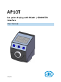
1
AP10T Set point display with RS485 / SIKONETZ5 interface User manual 319/15 Table of contents 1 General Informaton ................................................................................................... 5 1.1 Dokumentation ........................................................................................................5 1.2 Definitions ..............................................................................................................5 2 Intended use ............................................................................................................. 5 2.1 Switching on the supply voltage .................................................................................6 3 Brief description ....................................................................................................... 6 3.1 General ...................................................................................................................6 3.2 LCD display ..............................................................................................................6 3.2.1 Extended display range ..........................................................................................7 3.3 LED display ..............................................................................................................7 3.4 Keys .......................................................................................................................7 3.5 Communication ........................................................................................................7 3.6 Parameterization of the set point display .....................................................................8 3.6.1 Manual parameterization ........................................................................................8 3.6.1.1 Starting parameterization ...................................................................................8 3.6.1.2 Value input .......................................................................................................8 3.6.1.3 Value selection..................................................................................................8 3.6.1.4 Adjustable parameters ........................................................................................9 3.6.2 Parameterization via interface ................................................................................9 3.7 Warnings / Errors......................................................................................................9 3.7.1 Warnings .............................................................................................................9 3.7.2 Errors ..................................................................................................................9 3.8 System commands .................................................................................................. 10 3.8.1 Restore factory settings ....................................................................................... 10 3.8.2 Diagnosis ........................................................................................................... 10 4 Overview of parameters............................................................................................ 10 5 Communication via SIKONETZ 5 ................................................................................ 11 5.1 Interface ............................................................................................................... 11 5.2 Data exchange ....................................................................................................... 12 5.3 Telegram setup....................................................................................................... 12 5.3.1 Command ........................................................................................................... 12 5.3.2 Node address ...................................................................................................... 12 5.3.3 Parameter address ............................................................................................... 13 5.3.4 Control word ...................................................................................................... 13 5.3.5 Status word ........................................................................................................ 13 5.3.6 Data .................................................................................................................. 14 5.3.7 Check sum.......................................................................................................... 14 5.4 Synchronization ..................................................................................................... 15 5.5 Error telegram ........................................................................................................ 15 5.5.1 SIKONETZ5 error codes ......................................................................................... 16 AP10T Date: 03.09.2015 Art. No. 88127 Mod. status 319/15 Page 2 of 31 5.6 Communication errors ............................................................................................. 16 5.7 Communication monitoring ...................................................................................... 16 5.7.1 Bus-Timeout ....................................................................................................... 16 5.7.2 Programming interlock ......................................................................................... 17 5.8 Auto-ID................................................................................................................. 17 5.9 Parameter description ............................................................................................. 19 5.9.1 00h: Note address ............................................................................................... 19 5.9.2 01h: Baud rate ................................................................................................... 19 5.9.3 02h: Bus Timeout ................................................................................................ 19 5.9.4 03h: Response parameter to a set point write access ................................................ 20 5.9.5 04h: Keys enable time: Configuration start delay ..................................................... 20 5.9.6 05h: Key function enable1: Calibration enable......................................................... 20 5.9.7 06h: LED flashing ................................................................................................ 21 5.9.8 07h: LED3 (green right) ....................................................................................... 21 5.9.9 08h: LED2 (red left) ............................................................................................ 21 5.9.10 09h: LED1 (green left) ......................................................................................... 22 5.9.11 0Ah: Decimal places ............................................................................................ 22 5.9.12 0Dh: Display orientation ...................................................................................... 22 5.9.13 0Eh: Configuration programming mode................................................................... 23 5.9.14 39h: LED4 (red right)........................................................................................... 23 5.9.15 3Ah: LCD backlight flashing .................................................................................. 23 5.9.16 3Bh: LCD backlight white ..................................................................................... 24 5.9.17 3Ch: LCD backlight red ......................................................................................... 24 5.9.18 3Dh: Key function enable3: Configuration enable via keyboard .................................. 24 5.9.19 3Eh: Acknowledgement settings ............................................................................ 25 5.9.20 65h: Device identification .................................................................................... 25 5.9.21 67h: Software version .......................................................................................... 25 5.9.22 80h: Number of errors .......................................................................................... 26 5.9.23 81h until 8Ah: Errors ........................................................................................... 26 5.9.24 96h: Input errors ................................................................................................ 26 5.9.25 A0h: System commands........................................................................................ 27 5.9.26 A8h: Programming mode ...................................................................................... 27 5.9.27 CAh: Bus protocol ............................................................................................... 28 5.9.28 D0h: Response delay............................................................................................ 28 5.9.29 D2h: Auto-ID assignment ..................................................................................... 28 5.9.30 FAh: Status word................................................................................................. 29 5.9.31 FBh: Set point1 .................................................................................................. 29 5.9.32 FDh: Error telegram ............................................................................................. 29 5.9.33 FFh: Set point2 ................................................................................................... 30 6 Communication via Service Standard Protocol ............................................................ 30 6.1 General ................................................................................................................. 30 6.2 Error number encoding ............................................................................................ 30 6.3 Service protocol commands list................................................................................. 31 AP10T Date: 03.09.2015 Art. No. 88127 Mod. status 319/15 Page 3 of 31 AP10T Date: 03.09.2015 Art. No. 88127 Mod. status 319/15 Page 4 of 31 General Informaton 1 General Informaton 1.1 Dokumentation The following documents describe this product: The data sheet describes the technical data, the dimensions, the pin assignments, the accessories and the order key. The installation instructions describe the mechanical and electrical installation including all safety-relevant requirements and the associated technical specification. The user manual for commissioning and integrating the position indicator into a fieldbus syste These documents can also be downloaded at http://www.siko-global.com/p/ap10t. Additional information and support for this device can also be found there. 1.2 Definitions If not explicitly indicated otherwise, decimal values are given as figures without addition (e. g. 1234), binary values are labeled with b (e. g. 1011b), hexadecimal values are identified by h (e. g. 280h) after the figures. 2 Intended use The instrument is a set point display. Alpha-numeric set points can be transferred to the instrument via the RS485 interface and indicated via the backlit two-row LC display. Receipt of the set points can be acknowledged via the front button. The state of acknowledgment of the set points is signified by means of the two bi-color LEDs. Acknowledgment can also be performed via the interface by means of a control word. Additionally, it can activate the LEDs in order to realize various visualization tasks. Acknowledgment and button states are output in the status word. Some device parameters can be adjusted by means of the 3 buttons. You can change the set point, output the position value and adjust all device parameters via the integrated bus interface. AP10T Date: 03.09.2015 Art. No. 88127 Mod. status 319/15 Page 5 of 31 Brief description 2.1 Switching on the supply voltage The AP10T will be initialized after switching on the supply voltage. A display test is executed during initialization, the LEDs are lighted consecutively and the configutation parameters are loaded from the non-volative memory into the RAM of the controller. With the display still unconfigured all parameters are set to their default values. See to it that the bus will be connected only after correct adjustment of baud rate and ID (see chapter 3.6: Parameterization of the set point display and 5.8: Auto-ID). The AP10T functions with the data last parameterized. AP10T is in the normal operating state. According to the requirements of the application, the display can be parameterized via the SIKONETZ5 interface in this state. 3 Brief description 3.1 General The set point display has a two-line display with special characters and four control keys. The device is configured and activated via three symbol keys whereas received data is acknowledged via the fourth key. Two LEDs serve for signifying acknowledgement. LED left LED right Fig. 1: Control elements 3.2 LCD display The The display range is limited to -19999 … 99999. Values outside this range are displayed with "". With supply voltage applied to the set point display with factory settings, set points are displayed in both rows depending on validity and acknowledgment status. If there is no valid set point, "---" will be displayed in the 2nd row. A valid set point flashes until after acknowledgement. Two 6-digit set points can be displayed. Both rows are freely writeable. AP10T Date: 03.09.2015 Art. No. 88127 Mod. status 319/15 Page 6 of 31 Brief description 3.2.1 Extended display range Values up to -999999 can be displayed by means of the control word. If the relevant bit has been set and the value to be displayed is between -199999 and -999999, then the negative sign and the digit of the highest order will flash alternately. If the value range drops below 999999, "" will be displayed. 3.3 LED display With factory settings, the LED display works according to the following table. Operating mode There is no valid set point. There is a valid set point. LED both Status off Meaning LED left red green red green Set point1 not acknowledged Set point1 acknowledged Set point2 not acknowledged Set point2 acknowledged LED right Table 1: LED display in the Alpha-numeric display operating mode With the basic function of the LEDs inactivated, every LED can be controlled independently via the control word (see chapter 5.9.8 until 5.9.10 and 5.9.14: LEDs and chapter 5.3.4: Control word). 3.4 Keys With the Auto-ID function, the new ID is adopted by actuating the Auto-ID). Pressing the key (see chapter 5.8: key acknowledges a pending error (see chapter 3.7.2: Errors). Pressing the key starts the parameterization mode (see chapter 3.6: Parameterization of the set point display). With factory settings, the set points received are acknowledged by pressing the front button. 3.5 Communication Set point1 (in row 1) is received via the parameter FBh: Set point1. Likewise, set point2 (in row 2) is received via parameter FFh: Set point2. The data identifier must be correctly set in the respective control word. The data identifier serves for determining whether the data is interpreted and displayed as number or as alpha-numeric characters (ASCII) (see chapter 5.3.4: Control word). Control word: (see chapter 5.3.4) In the control word, the respective type (number or character string) and the validity of the set point are transferred to the display. Additionally, the set point can be acknowledged via the control word. AP10T Date: 03.09.2015 Art. No. 88127 Mod. status 319/15 Page 7 of 31 Brief description Status word: (see chapter 5.3.5) Type, validity and acknowledgement status of the set points are recorded in the status word. 3.6 Parameterization of the set point display The set point display can be fully parameterized via the bus interface. You can configure manually via keyboard the most significant bus parameters (node address and baud rate). 3.6.1 Manual parameterization 3.6.1.1 Starting parameterization After applying supply voltage and passing initialization, the set point display will be on the uppermost level of the menu structure (default/factory settings). By actuating the key, the set node address and baud rate is displayed. Parameterization starts if this key is actuated during the enable period (see parameter 04h: Keys enable time: Configuration start delay and 3Dh: Key function enable3: Configuration enable via keyboard). 3.6.1.2 Value input Enter values via the key and the key. Confirm values entered by pressing the key. - decimal place selection key - value input key 3.6.1.3 Value selection For some parameters you can select values from a list. Direct value input is not possible there. Pressing the key, the value can be selected from the list. By pressing the selection is confirmed. AP10T Date: 03.09.2015 Art. No. 88127 Mod. status 319/15 key, the Page 8 of 31 Brief description 3.6.1.4 Adjustable parameters The following parameters can be adjusted. Display ID KBAUD Parameter Node-ID Baud rate Protcl Protocol BUS TO Inhibt CODE Bus-Timeout Response delay time System commands Options 1 … 127 19.2 kbaud 57.6 kbaud 115.2 kbaud SIKONETZ5 Service-standard 0 … 20 0 … 10 Reset factory settings (see chapter 3.8.1) Start diagnosis (see chapter 3.8.2) Table 2: Manually adjustable parameters 3.6.2 Parameterization via interface The set point display can be completely parameterized in the RS485 interface (see chapter 5: Communication via SIKONETZ 5). 3.7 Warnings / Errors 3.7.1 Warnings No warnings are output. 3.7.2 Errors Errors are signified via the display (written in red) and via the interface. The cause of error must be removed to enable resumption of normal operation. Afterwards you can acknowledge or delete the error message by pressing the key or via the interface (see chapter 5.3.4: Control word). (For signaling see chapter 5.3.5: Status word and chapter 3.8.2: Diagnosis) Display CS bUS to bUS Error code SIKONETZ5 0080h 0081h Bit assignment in Error the status word 7 Checksum SIKONETZ5 7 Timeout SIKONETZ5 Table 3: Error messages AP10T Date: 03.09.2015 Art. No. 88127 Mod. status 319/15 Page 9 of 31 Overview of parameters 3.8 System commands 3.8.1 Restore factory settings There are various options for restoring the factory settings of the device: Access Manuell Coding SIKONETZ5 (see parameter A0h: System commands) A0h 11100 11102 11105 1 2 5 Factory settings are restored all parameters all except bus parameters only bus parameters all parameters all except bus parameters only bus parameters Table 4: Access to factory settings 3.8.2 Diagnosis To receive a list of device errors that occurred switch the device to the diagnosis mode. Enter CODE "200000" in parameterization (see chapter 3.6.1: Manual parameterization) and confirm by pressing the key. Any errors occurring are output indicating the error number and total of occurrences in the upper row. The type of error is shown in the lower row. Error number 1 contains the latest error. The oldest error is output with the highest error number. 4 Overview of parameters AP10T Name Description 00h: Note address 01h: Baud rate 02h: Bus Timeout 03h: Response parameter to a set point write access 04h: Keys enable time: Configuration start delay 05h: Key function enable1: Calibration enable 06h: LED flashing 07h: LED3 (green right) 08h: LED2 (red left) 09h: LED1 (green left) 0Ah: Decimal places 0Dh: Display orientation 0Eh: Configuration programming mode Node address Baud rate of the RS485 interface Indication of bus timeout in x100 ms Defines the response to the command "Write set point" Period of key actuation in order to start configuration. Enable calibration Date: 03.09.2015 All LEDs flashing LED green right (LED3) LED red left (LED2) LED green left (LED1) Number of decimal places Display orientation Basic setting of programming interlock Art. No. 88127 Mod. status 319/15 see page 19 19 19 20 20 20 21 21 21 22 22 22 23 Page 10 of 31 Communication via SIKONETZ 5 Name Description 39h: LED4 (red right) 3Ah: LCD backlight flashing 3Bh: LCD backlight white 3Ch: LCD backlight red 3Dh: Key function enable3: Configuration enable via keyboard 3Eh: Acknowledgement settings 65h: Device identification 67h: Software version 80h: Number of errors 81h until 8Ah: Errors 96h: Input errors A0h: System commands A8h: Programming mode CAh: Bus protocol D0h: Response delay LED red right (LED4) Flashing LCD backlight LCD backlight white LCD backlight red Configuration enable D2h: Auto-ID assignment FAh: Status word FBh: Set point1 FDh: Error telegram FFh: Set point2 see page 23 23 24 24 24 Acknowledgment settings SIKONETZ5 device identification (AP10T = 10) Software version Number of error incidents Error list Input error list Various system commands Programming disable Setting of the communication protocol Delay until a SIKONETZ5 bus telegram is answered. Automated node address assignment Device status Set point1 (alpha-numeric display) Error telegram Target position 25 25 25 26 26 26 27 27 28 28 28 29 29 29 30 Table 5: Parameter description 5 Communication via SIKONETZ 5 5.1 Interface RS485 interface Available baud rates: 19.2 kBit / 57.6 kBit (factory setting) / 115.2 kBit No parity, 8 data bits, 1 stop bit, no handshake AP10T Date: 03.09.2015 Art. No. 88127 Mod. status 319/15 Page 11 of 31 Communication via SIKONETZ 5 5.2 Data exchange The protocol functions according to the master – slave principle. The set point display acts as a slave. Every instance of communication must be initiated by the master. When the master has sent a command telegram, the slave sends a reply telegram. Broadcast commands are an exception, they remain always unanswered by the slave. The protocol is optimized for cyclical data exchange. The relevant data such as set point and actual value as well as control and status words can be transferred between master and slave by a single telegram exchange. The parameter to be returned by the slave as a reply to the master's Write set point command can be defined via the "Write set point reply parameter". 5.3 Telegram setup Control word (CW), status word (SW) and data are transferred in the Big-Endian format. 1stbyte 2ndbyte 3rdbyte Command Node Parameter address address 4thbyte 5thbyte 6thbyte 7thbyte 8thbyte 9thbyte 10thbyte high Byte low Byte SW MSB LSB Check sum Data Table 6: Command telegram (from master) 1stbyte 2ndbyte 3rdbyte Command Node Parameter address address 4thbyte 5thbyte 6thbyte 7thbyte 8thbyte 9thbyte 10thbyte high Byte low Byte CW MSB LSB Check sum Data Table 7: Reply telegram (from slave) 5.3.1 Command The following access types are provided by SIKONETZ5. Access code Meaning 00h read 5.3.2 01h write 02h broadcast Description The master requests the addressed slave to output the relevant value in a response telegram. The master requests the addressed slave to accept the value transferred in the same telegram. The master requests all connected slaves to execute the command transferred in the same telegram. Node address The device address can be freely set in the range of 0 to 127. The delivered devices are preset to node address 31 ex works and must be reset to the desired address to enable their operation with multiple slaves on the SIKONETZ5 fieldbus (see parameter 00h: Note address and chapter 5.8: Auto-ID). Each address can be assigned in the fieldbus only once! AP10T Date: 03.09.2015 Art. No. 88127 Mod. status 319/15 Page 12 of 31 Communication via SIKONETZ 5 5.3.3 Parameter address A distinct address is assigned to every parameter (e. g. calibration value) or functional value (e. g. set point) (see chapter 5.9: Parameter description). 5.3.4 Control word The control word consists of 16 bits. Control word 15 14 13 12 11 MSB High Byte 10 9 8 7 6 5 4 Low Byte 3 2 1 0 LSB The following table lists the designations of the individual bits of the control word and their meanings. Bit 0 1 2 3 4 5 6 7 8 9 10 11 12 13 14 15 Meaning reserved reserved Validity of set point1 Display range reserved Error Acknowledgement of set point2 Data identifier reserved Validity of set point2 Acknowledgement of set point1 LED1 green left LED3 green right LED4 red right LED2 red left LED blinking Value = 0 ever 0 ever 0 invalid standard ever 0 not acknowledged not acknowledged number ever 0 invalid not acknowledged Off Off Off Off Off Value = 1 valid extended acknowledged acknowledged ASCII valid acknowledged On On On On On Table 8: Control word 5.3.5 Status word The status word indicates the current status of AP10T. It consists of 16 bits. Status word 15 14 13 12 11 MSB High Byte AP10T Date: 03.09.2015 10 9 8 7 Art. No. 88127 6 5 4 Low Byte 3 Mod. status 319/15 2 1 0 LSB Page 13 of 31 Communication via SIKONETZ 5 The following table lists the designations of the individual bits of the status word and their meanings. Bit 0 1 2 3 4 5 6 7 8 9 10 11 12 13 Meaning reserved reserved Validity set point1 Acknowledgement of set point2 reserved Acknowledgement of set point1 reserved General error front key data identifier Validity set point2 reserved reserved key Value = 0 ever 0 ever 0 invalid not acknowledged ever 0 not acknowledged ever 0 not present not actuated number invalid ever 0 ever 0 not actuated Value = 1 valid acknowledged acknowledged is present actuated ASCII-String valid actuated 14 key not actuated actuated 15 key not actuated actuated Table 9: Status word 5.3.6 Data Range for data exchange. Size: 4 bytes. 5.3.7 Check sum For checking error-free data transfer, a check sum is formed at the end of the telegram. The check sum is the exclusive-OR-link of bytes 1 … 9: Check sum [Byte10] = [Byte1] XOR [Byte2] XOR [Byte3] XOR [Byte4] XOR [Byte5] XOR [Byte6] XOR [Byte7] XOR [Byte8] XOR [Byte9] The following applies for checking the telegram received: [Byte1] XOR [Byte2] XOR [Byte3] XOR [Byte4] XOR [Byte5] XOR [Byte6] XOR [Byte7] XOR [Byte8] XOR [Byte9] XOR [Byte 10] = 0 With a result unequal 0 a transmission error is to be assumed. When a check sum error is detected, it is answered with an error telegram. With three subsequent check sum errors, the check sum SIKONETZ5 error will be triggered. AP10T Date: 03.09.2015 Art. No. 88127 Mod. status 319/15 Page 14 of 31 Communication via SIKONETZ 5 5.4 Synchronization Processing of the "Restore factory settings" system command may take up to 600 ms. Acknowledgment is reported only after proper updating of all parameters in the non-volatile memory. Byte/telegram synchronization is via "Timeout". The intervals between the individual bytes of a telegram must not exceed the value of 10 ms. If an addressed device does not respond, the master must not send another telegram earlier than after 30 ms. 5.5 Error telegram Illegal entries are replied with an error telegram. An error telegram consists of parameter address FDh and an error code. The error code is in the data section of the reply telegram. The error code is divided in two bytes. Code 1 describes the error proper, code 2 contains additional information if available. In the following example an attempt was made at writing a value of 90 to the key enable time parameter address. However, a maximum value of only 60 is admissible for this parameter. 1stbyte 2ndbyte 3rdbyte 4thbyte 5thbyte 6thbyte 7thbyte 8thbyte 9thbyte 10thbyte Command Node Parameter address address 01h 01h 04h CW 00h 00h Data 00h 00h 00h Check sum 5Ah 5Eh Table 10: Telegram from master to slave 1stbyte 2ndbyte 3rdbyte 4thbyte 5thbyte 6thbyte 7thbyte 8thbyte 9thbyte 10thbyte Command Node Parameter address address 01h 01h FDh SW 00h 81h 00h 00h Data Check Code 2 Code 1 sum 02h 82h FCh Table 11: Reply telegram from slave AP10T Date: 03.09.2015 Art. No. 88127 Mod. status 319/15 Page 15 of 31 Communication via SIKONETZ 5 5.5.1 SIKONETZ5 error codes Code 2 00h 00h 00h 01h 02h 00h 00h 01h 02h 00h 03h Code 1 80h 81h 82h 83h 84h 85h Description Check sum SIKONETZ5 Timeout SIKONETZ5 Value rage exceeded / inadequate Value < MIN Value > MAX Unknown parameter Access is not supported write attempt to read only read attempt to write only Error due to device status Programming locked Table 12: SIKONETZ5 error codes 5.6 Communication errors Error states of the slave are signified with the status word.7 = 1. Every error must be acknowledged with control word.5 = 0/1 or by pressing the key. If the cause of the error has not been resolved at the time of acknowledgment, the error will not be reset or triggered anew, resp. Errors that have not been acknowledged can be read via a read command on Parameter FDh: Error telegram. The error code will be output (see chapter 3.7.2: Errors and 5.5.1: SIKONETZ5 error codes). A list of errors occurring is output in Diagnosis (see chapter 3.8.2). 5.7 Communication monitoring 5.7.1 Bus-Timeout Bus timeout monitoring is activated by configuring a valid time value (>0) for timeout (see parameter 02h: Bus Timeout). The first telegram received by the slave starts time monitoring. Every new telegram recognized as valid by a slave (correct check sum) triggers time monitoring. If timeout occurs, this will result in the Timeout SIKONETZ5 error. After establishing cyclic communication between master and slave, this function can detect a broken cable of the connection line for instance and signal the defect. AP10T Date: 03.09.2015 Art. No. 88127 Mod. status 319/15 Page 16 of 31 Communication via SIKONETZ 5 5.7.2 Programming interlock Programming interlock is controlled via parameter 0Eh: Configuration programming mode. This parameter being enabled, the interlock must be canceled prior to write access to a lockable parameter (see entry at the relevant parameter) by applying a write access to parameter A8h: Programming mode. Correspondingly, the interlock should be enabled again immediately after a write access. This mechanism enhances protection against unintentional parameterization. Write access to locked parameters is replied with "Error due to device state" (see chapter 5.5.1: SIKONETZ5 error codes). 5.8 Auto-ID This function facilitates first commissioning of the devices in the plant. The node numbers can be assigned by the superordinate control or by pressing the relevant button on the device concerned. The functional principle is illustrated in Fig. 2: Auto-ID function. The Node-ID 1Fh (31d) is factory-set. Now, the SIKONETZ5 master must send a write command on parameter D2h: Auto-ID assignment with the new Node ID to be set to the bus subscriber(s) with the current Node-ID 1Fh and wait for an SIKONETZ5 response. A write command on devices with a node ID different from 1Fh is responded to with an error message. "New ID" will be displayed on all devices that have the current Node-ID 1Fh. The user must press the key on the device intended to adopt the new Node ID. Afterwards, this device sends a SIKONETZ5 response with the parameter D2h: Auto-ID assignment. The new Node-ID is taken over and stored in the EEPROM. The initialization phase is finally repeated so that the new Node ID applies henceforth. All other devices do not react. Afterwards, the control unit can execute a read command on a parameter for the node with the node ID 1Fh for instance in order to detect any other devices with node ID 1Fh present in the bus. If so, the procedure may be repeated until all devices have received the desired Node-ID. The Auto-ID function is aborted in the AP10T when an illegal value was sent for the new ID. Error messages will be returned in this case. Use of this function is optional. The node numbers can also be set via parameterization (see chapter 3.6: Parameterization of the set point display). AP10T Date: 03.09.2015 Art. No. 88127 Mod. status 319/15 Page 17 of 31 Communication via SIKONETZ 5 Fig. 2: Auto-ID function AP10T Date: 03.09.2015 Art. No. 88127 Mod. status 319/15 Page 18 of 31 Communication via SIKONETZ 5 5.9 Parameter description 5.9.1 00h: Note address Setting of the SIKONETZ5 node address. Changes become active only after restart of the device. Parameter address Description Access EEPROM Programming mode Data type Default Data content 5.9.2 00h node address rw yes yes UNSIGNED 8 31 1 … 127 01h: Baud rate Setting of the SIKONETZ5 baud rate. Changes become active only after restart of the device. Parameter address Description Access EEPROM Programming mode Data type Default Data content 5.9.3 01h Baud rate of the RS485 interface rw yes yes UNSIGNED 8 57600 kBaud 0 = 19200 1 = 57600 2 = 115200 02h: Bus Timeout See chapter 5.7.1: Bus-Timeout. Parameter address Description Access EEPROM Programming mode Data type Default Data content AP10T 02h Indication of bus timeout in x100 ms rw yes yes UNSIGNED 8 0 0 … 20 Date: 03.09.2015 Art. No. 88127 Mod. status 319/15 Page 19 of 31 Communication via SIKONETZ 5 5.9.4 03h: Response parameter to a set point write access Parameter address Description Access EEPROM Programming mode Data type Default Data content 5.9.5 03h This parameter defines the response to the command "Write set point" rw yes yes UNSIGNED 8 0 0 = set point 04h: Keys enable time: Configuration start delay Configuration start delay (key enable time) is set via parameter 04h. Parameter address Description Access EEPROM Programming mode Data type Default Data content 5.9.6 04h Duration of key actuation to start configuration. rw yes yes UNSIGNED 8 5 1 … 60 s 05h: Key function enable1: Calibration enable The parameter 05h indicates whether calibration of the position value is enabled via key actuation. Parameter address Description Access EEPROM Programming mode Data type Default Data content AP10T 05h Key enable rw yes yes UNSIGNED 8 1 0: Calibration disabled 1: Calibration enabled Date: 03.09.2015 Art. No. 88127 Mod. status 319/15 Page 20 of 31 Communication via SIKONETZ 5 5.9.7 06h: LED flashing Flashing of the LEDs can be set via parameter 06h (see chapter 3.3: LED display). This setting applies to all LEDs. Parameter address Description Access EEPROM Programming mode Data type Default Data content 5.9.8 06h Flashing of all LEDs rw yes yes UNSIGNED 8 0 0 = no flashing 1 = any glowing LED is flashing 07h: LED3 (green right) LED3 (green, right) can be set via parameter 07h (see chapter 3.3: LED display). The control word can be freely accessed only if the LED is switched off here. Parameter address Description Access EEPROM Programming mode Data type Default Data content 5.9.9 07h LED green right (LED3) rw yes yes UNSIGNED 8 1 0 = Off 1 = position-dependent 08h: LED2 (red left) LED2 (red, left) can be set via parameter 08h (see chapter 3.3: LED display). The control word can be freely accessed only if the LED is switched off here. Parameter address Description Access EEPROM Programming mode Data type Default Data content AP10T 08h LED red left (LED2) rw yes yes UNSIGNED 8 1 0 = Off 1 = position-dependent Date: 03.09.2015 Art. No. 88127 Mod. status 319/15 Page 21 of 31 Communication via SIKONETZ 5 5.9.10 09h: LED1 (green left) LED1 (green, left) can be set via parameter 09h (see chapter 3.3: LED display). The control word can be freely accessed only if the LED is switched off here. Parameter address Description Access EEPROM Programming mode Data type Default Data content 5.9.11 09h LED green left (LED1) rw yes yes UNSIGNED 8 1 0 = Off 1 = position-dependent 0Ah: Decimal places The parameter 0Ah indicates the number of decimal places. Parameter address Description Access EEPROM Programming mode Data type Default Data content 5.9.12 0Ah number of decimal places rw yes yes UNSIGNED 8 0 0…4 0Dh: Display orientation Display orientation can be set via parameter 0Dh. Parameter address Description Access EEPROM Programming mode Data type Default Data content AP10T 0Dh display orientation rw yes yes UNSIGNED 8 0 0 = 0° 1 = 180° rotated Date: 03.09.2015 Art. No. 88127 Mod. status 319/15 Page 22 of 31 Communication via SIKONETZ 5 5.9.13 0Eh: Configuration programming mode Basic settings of programming interlock (see chapter 5.7.2: Programming interlock). Parameter address Description Access EEPROM Programming mode Data type Default Data content 5.9.14 0Eh Configuration programming mode rw yes yes UNSIGNED 8 0 0 = no active programming interlock 1 = active programming interlock 39h: LED4 (red right) The LED4 (red, right) can be set via parameter 39h (see chapter 3.3: LED display). Free access via the control word is only enabled if the LED is switched off here. Parameter address Description Access EEPROM Programming mode Data type Default Data content 5.9.15 39h LED red right (LED4) rw yes yes UNSIGNED 8 1 0 = Off 1 = position-dependent 3Ah: LCD backlight flashing Flashing of the LCD backlight can be set via parameter 3Ah. This setting applies to either color. Parameter address Description Access EEPROM Programming mode Data type Default Data content AP10T 3Ah Flashing of the LCD backlight rw yes yes UNSIGNED 8 0 0 = no flashing 1 = the current backlight is flashing. Date: 03.09.2015 Art. No. 88127 Mod. status 319/15 Page 23 of 31 Communication via SIKONETZ 5 5.9.16 3Bh: LCD backlight white The white LCD backlight can be set via parameter 3Bh. Parameter address Description Access EEPROM Programming mode Data type Default Data content 5.9.17 3Bh LCD backlight white rw yes j yes a UNSIGNED 8 1 0 = Off 1 = On 3Ch: LCD backlight red The red LCD backlight can be set via parameter 3Ch. Parameter address Description Access EEPROM Programming mode Data type Default Data content 5.9.18 3Ch LCD backlight red rw yes yes UNSIGNED 8 1 0 = Off 1 = On 3Dh: Key function enable3: Configuration enable via keyboard Parameter 3Dh indicates whether configuration via key actuation is enabled. Parameter address Description Access EEPROM Programming mode Data type Default Data content AP10T 3Dh Key enable rw yes yes UNSIGNED 8 1 0: configuration disabled 1: configuration enabled Date: 03.09.2015 Art. No. 88127 Mod. status 319/15 Page 24 of 31 Communication via SIKONETZ 5 5.9.19 3Eh: Acknowledgement settings Parameter 3Eh serves for determining the key to be used as acknowledgement key. Parameter address Description Access EEPROM Programming mode Data type Default Data content 5.9.20 65h Device identification ro no no UNSIGNED 8 10 10 = 0Ah = AP10T 67h: Software version Parameter address Description Access EEPROM Programming mode Data type Default Data content AP10T 0: key 2: Up and Left key 65h: Device identification Parameter address Description Access EEPROM Programming mode Data type Default Data content 5.9.21 3Eh acknowledgement settings rw yes yes UNSIGNED 8 0 67h Software version number ro no no UNSIGNED 32 100 (= version 1.00) or higher Date: 03.09.2015 Art. No. 88127 Mod. status 319/15 Page 25 of 31 Communication via SIKONETZ 5 5.9.22 80h: Number of errors See chapter 3.7: Warnings / Errors. Parameter address Description Access EEPROM Programming mode Data type Default Data content 5.9.23 80h Number of errors recorded ro yes no UNSIGNED 8 0 0 … 10 81h until 8Ah: Errors See chapter 3.7: Warnings / Errors. The oldest error is found under parameter address 81h, the most recent error is found under the highest address. Parameter address Description Access EEPROM Programming mode Data type Default Data content 5.9.24 81h until 8Ah error ro yes no UNSIGNED 16 0 see chapter 3.7.2: Errors 96h: Input errors Output of a list (10 entries) of input errors (see chapter 5.5.1: SIKONETZ5 error codes). The list is deleted with initialization of the device at program start (reset or power-on). The error number must be transferred in data byte 3 of the telegram. Data byte 3 with the request = 0 number of errors occurring is reported. Data byte 3 with the request = 1 error number 1 (latest error) is reported. Example: Telegram structure of master: latest error (= no. 1) shall be read: Command 00h ID 1Fh Parameter 96h ZSW XX YY Error number 01h 00h 00h 00h CS NNh Error number Error code 01h 00h 00h 83h CS NNh Telegram structure of slave: latest error (1) is output: Command 00h AP10T ID 1Fh Parameter 96h Date: 03.09.2015 ZSW XX YY Art. No. 88127 Mod. status 319/15 Page 26 of 31 Communication via SIKONETZ 5 Parameter address Description Access EEPROM Programming mode Data type Default Data content 5.9.25 96h error ro yes no UNSIGNED 16 0 see chapter 5.5.1: SIKONETZ5 error codes A0h: System commands Various system commands can be executed via parameter A0h. Parameter address Description Access EEPROM Programming mode Data type Default Data content 5.9.26 A0h System commands wo no no UNSIGNED 32 0 1: Reset all parameters to factory settings 2: Reset all parameters to factory settings, except the bus parameters 5: Reset only the bus parameters to factory settings 9: Software reset (warm start) A8h: Programming mode Programming interlock (see chapter 5.7.2: Programming interlock). Parameter address Description Access EEPROM Programming mode Data type Default Data content AP10T A8h Programming mode wo yes yes UNSIGNED 8 0 0 = parameter programming disabled 1 = parameter programming enabled Date: 03.09.2015 Art. No. 88127 Mod. status 319/15 Page 27 of 31 Communication via SIKONETZ 5 5.9.27 CAh: Bus protocol Changes become active only after restart of the device. Parameter address Description Access EEPROM Programming mode Data type Default Data content 5.9.28 CAh Protocol of the RS485 interface rw yes yes UNSIGNED 8 0 0 = SIKONETZ5 1 = Service protocol D0h: Response delay Number of internal program cycles deferred before responding to a SIKONETZ5 bus telegram. The response to a telegram can be delayed until the master is ready to receive. The value 10 corresponds to a delay of approx. 5 ms. Parameter address Description Access EEPROM Programming mode Data type Default Data content 5.9.29 D0h Response delay rw yes yes UNSIGNED 8 0 0 … 20 D2h: Auto-ID assignment See chapter 5.8: Auto-ID. Parameter address Description Access EEPROM Programming mode Data type Default Data content AP10T D2h Automated assignment of a node address wo yes, the node number is stored with its adoption no UNSIGNED 8 1 … 31 Date: 03.09.2015 Art. No. 88127 Mod. status 319/15 Page 28 of 31 Communication via SIKONETZ 5 5.9.30 FAh: Status word The status word can be read via this parameter. Bit 4: "Target window1 static" is deleted in the status word with this operation. With this function, it can be detected whether the actual position was ever in the target window even if this is not the case at present (see chapter 5.3.5: Status word). Parameter address Description Access EEPROM Programming mode Data type Default Data content 5.9.31 FAh Read status word and delete "Target window1 static" ro no no UNSIGNED 16 0 FBh: Set point1 The current set point1 can be written and read via address FBh. Parameter address Description Access EEPROM Programming mode Data type Default Data content 5.9.32 FBh Set point1 rw no no UNSIGNED 32 0h … FFFFFFFFh FDh: Error telegram Illegal entries are answered with an error telegram. An error telegram consists of the parameter address FDh and an error code (see chapter 5.5: Error telegram). Parameter address Description Access EEPROM Programming mode Data type Default Data content AP10T FDh Error telegram no no UNSIGNED 32 see chapter 5.5: Error telegram Date: 03.09.2015 Art. No. 88127 Mod. status 319/15 Page 29 of 31 Communication via Service Standard Protocol 5.9.33 FFh: Set point2 The current set point2 can be written and read via address FFh. Parameter address Description Access EEPROM Programming mode Data type Default Data content FFh Set point2 rw no no SIGNED / UNSIGNED 32 (depending on the transmission mode) 0h … FFFFFFFFh 6 Communication via Service Standard Protocol 6.1 General The service protocol enables the control of the position indicator via ASCII commands. No additional devices must be connected to the RS485 interface since this protocol is not buscompatible. An ASCII terminal sends a letter and additional parameters if required (ASCII). Subsequently, the set point displaysends a reply with a concluding <CR>. Available baud rates: Additional settings: 6.2 19.2 kBit / 57.6 kBit (factory setting) / 115.2 kBit No parity, 8 data bits, 1 stop bit, no handshake Error number encoding The following error messages are returned in case of wrong input. Error number ?1 ?2 Description input of illegal parameter number illegal value range Table 13: Error number encoding AP10T Date: 03.09.2015 Art. No. 88127 Mod. status 319/15 Page 30 of 31 Communication via Service Standard Protocol 6.3 Service protocol commands list Command Length Reply Description Ay 2/17 "AP10 SN5 zW xxxx>" Device type / software version y=0: hardware version; z = H y=1: software version; z = S Sxxxxx 6/2 ">" System commands x=11100: all parameters into basic state After restart, the factory settings will be active, this applies to bus protocol and baud rate as well. x=11101: reset all to factory settings, except bus parameters x=11102: only bus parameters into basic state x=11105: activate bootloader Z 1/11 "±xxxxxxxx>" Output actual position (AP10T = 0) Table 14: Service protocol commands list AP10T Date: 03.09.2015 Art. No. 88127 Mod. status 319/15 Page 31 of 31