1
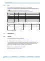
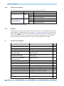
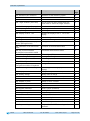
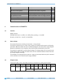
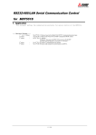
AP10 Absolute Position Indicator with RS485 / SIKONETZ5 interface User manual 319/15 Table of contents 1 General Informaton ................................................................................................... 5 1.1 Dokumentation ........................................................................................................5 1.2 Definitions ..............................................................................................................5 2 Intended use ............................................................................................................. 5 2.1 Switching on the supply voltage .................................................................................6 3 Display and control keys ............................................................................................ 6 3.1 General ...................................................................................................................6 3.2 LCD display ..............................................................................................................6 3.2.1 Extended display range ..........................................................................................7 3.3 LED display ..............................................................................................................7 3.4 Keys .......................................................................................................................7 4 Functional Description ............................................................................................... 7 4.1 Operating modes ......................................................................................................7 4.1.1 Position-bound operating modes .............................................................................8 4.1.1.1 Positioning .......................................................................................................8 4.1.1.2 Loop positioning ............................................................................................. 10 4.1.2 Alpha-numeric display operating mode ................................................................... 11 4.2 Battery buffering .................................................................................................... 12 4.3 Parameterization of the position indicator ................................................................. 12 4.3.1 Manual parameterization ...................................................................................... 12 4.3.1.1 Starting parameterization ................................................................................. 12 4.3.1.2 Value input ..................................................................................................... 12 4.3.1.3 Value selection................................................................................................ 13 4.3.1.4 Adjustable parameters ...................................................................................... 13 4.3.2 Parameterization via interface .............................................................................. 13 4.4 Warnings / Errors.................................................................................................... 13 4.4.1 Warnings ........................................................................................................... 13 4.4.2 Errors ................................................................................................................ 14 4.5 System commands .................................................................................................. 14 4.5.1 Calibration ......................................................................................................... 14 4.5.2 Restore factory settings ....................................................................................... 15 4.5.3 Diagnosis ........................................................................................................... 15 5 Overview of parameters............................................................................................ 15 6 Communication via SIKONETZ 5 ................................................................................ 17 6.1 Interface ............................................................................................................... 17 6.2 Data exchange ....................................................................................................... 17 6.3 Telegram setup....................................................................................................... 17 6.3.1 Command ........................................................................................................... 18 6.3.2 Node address ...................................................................................................... 18 6.3.3 Parameter address ............................................................................................... 18 AP10 Date: 03.09.2015 Art. No. 86855 Mod. status 319/15 Page 2 of 46 6.3.4 Control word ...................................................................................................... 18 6.3.5 Status word ........................................................................................................ 19 6.3.6 Data .................................................................................................................. 20 6.3.7 Check sum.......................................................................................................... 20 6.4 Synchronization ..................................................................................................... 20 6.5 Error telegram ........................................................................................................ 21 6.5.1 SIKONETZ5 error codes ......................................................................................... 21 6.6 Communication errors ............................................................................................. 22 6.7 Communication monitoring ...................................................................................... 22 6.7.1 Bus-Timeout ....................................................................................................... 22 6.7.2 Programming interlock ......................................................................................... 22 6.8 Auto-ID................................................................................................................. 23 6.9 Parameter description ............................................................................................. 25 6.9.1 00h: Note address ............................................................................................... 25 6.9.2 01h: Baud rate ................................................................................................... 25 6.9.3 02h: Bus Timeout ................................................................................................ 25 6.9.4 03h: Response parameter to a set point write access ................................................ 26 6.9.5 04h: Keys enable time: Configuration start delay ..................................................... 26 6.9.6 05h: Key function enable1: Calibration enable......................................................... 26 6.9.7 06h: LED flashing ................................................................................................ 27 6.9.8 07h: LED3 (green right) ....................................................................................... 27 6.9.9 08h: LED2 (red left) ............................................................................................ 27 6.9.10 09h: LED1 (green left) ......................................................................................... 28 6.9.11 0Ah: Decimal places ............................................................................................ 28 6.9.12 0Bh: Display divisor (ADI) .................................................................................... 28 6.9.13 0Ch: Direction indicators (CW, CCW) ....................................................................... 29 6.9.14 0Dh: Display orientation ...................................................................................... 29 6.9.15 0Eh: Configuration programming mode ................................................................... 29 6.9.16 1Bh: Counting direction ....................................................................................... 30 6.9.17 1Ch: Resolution per revolution .............................................................................. 30 6.9.18 1Eh: Offset value ................................................................................................ 31 6.9.19 1Fh: Calibration value .......................................................................................... 31 6.9.20 20h: Target window1 (near field) .......................................................................... 31 6.9.21 21h: Positioning type (loop type).......................................................................... 32 6.9.22 22h: Loop length ................................................................................................ 32 6.9.23 28h: Operating mode ........................................................................................... 32 6.9.24 30h: Display in the 2nd row ................................................................................... 33 6.9.25 31h: Target window2 (extended) ........................................................................... 33 6.9.26 32h: Target window2 visualization ......................................................................... 33 6.9.27 33h: Application of the display divisor (ADI application) .......................................... 34 6.9.28 34h: Formation of the differential value ................................................................. 34 6.9.29 35h: Key function enable2: Incremental measurement enable .................................... 34 6.9.30 39h: LED4 (red right)........................................................................................... 35 6.9.31 3Ah: LCD backlight flashing .................................................................................. 35 AP10 Date: 03.09.2015 Art. No. 86855 Mod. status 319/15 Page 3 of 46 6.9.32 6.9.33 6.9.34 6.9.35 6.9.36 6.9.37 6.9.38 6.9.39 6.9.40 6.9.41 6.9.42 6.9.43 6.9.44 6.9.45 6.9.46 6.9.47 6.9.48 6.9.49 6.9.50 6.9.51 6.9.52 6.9.53 6.9.54 6.9.55 6.9.56 6.9.57 3Bh: LCD backlight white ..................................................................................... 35 3Ch: LCD backlight red ......................................................................................... 36 3Dh: Key function enable3: Configuration enable via keyboard .................................. 36 3Eh: Acknowledgement settings ............................................................................ 36 3Fh: Display factor .............................................................................................. 37 63h: Battery voltage............................................................................................ 38 65h: Device identification .................................................................................... 38 67h: Software version .......................................................................................... 38 80h: Number of errors .......................................................................................... 39 81h until 8Ah: Errors ........................................................................................... 39 96h: Input errors ................................................................................................ 39 A0h: System commands........................................................................................ 40 A7h: Calibration travel ......................................................................................... 40 A8h: Programming mode ...................................................................................... 41 AAh: Freeze actual value ...................................................................................... 41 C5h: ADC values of the sensor ............................................................................... 41 CAh: Bus protocol ............................................................................................... 42 CFh: Period counter ............................................................................................. 42 D0h: Response delay............................................................................................ 42 D2h: Auto-ID assignment ..................................................................................... 43 FAh: Status word................................................................................................. 43 FBh: Set point1 .................................................................................................. 43 FCh: Differential value ......................................................................................... 44 FDh: Error telegram ............................................................................................. 44 FEh: Position value.............................................................................................. 44 FFh: Set point2 ................................................................................................... 45 7 Communication via Service Standard Protocol ............................................................ 45 7.1 General ................................................................................................................. 45 7.2 Error number encoding ............................................................................................ 45 7.3 Service protocol commands list................................................................................. 46 AP10 Date: 03.09.2015 Art. No. 86855 Mod. status 319/15 Page 4 of 46 General Informaton 1 General Informaton 1.1 Dokumentation The following documents describe this product: The data sheet describes the technical data, the dimensions, the pin assignments, the accessories and the order key. The installation instructions describe the mechanical and electrical installation including all safety-relevant requirements and the associated technical specification. The user manual for commissioning and integrating the position indicator into a fieldbus syste These documents can also be downloaded at http://www.siko-global.com/p/ap10. Additional information and support for this device can also be found there. 1.2 Definitions If not explicitly indicated otherwise, decimal values are given as figures without addition (e. g. 1234), binary values are labeled with b (e. g. 1011b), hexadecimal values are identified by h (e. g. 280h) after the figures. 2 Intended use Absolute position indicator with hollow shaft suitable for direct shaft mounting. Actual and target values are indicated via the backlit two-row LC display. A direction indicator (arrow) is blended in if the actual value deviates from the target value including the adjustable target window. The direction of the arrow indicates the direction of shaft movement necessary to reach the target. Additionally, various visualization tasks can be realized by means of two bicolor LEDs. The device parameters can be adjusted by means of 3 keys. You can change the set point, output the position value and adjust all device parameters via the integrated bus interface. Scanning is magnetically-incremental. In the currentless state, scanning and saving of changes of the position value are battery-supported. The state of charge of the replaceable battery is monitored and signified. Display and interface are active with external power supply only. AP10 Date: 03.09.2015 Art. No. 86855 Mod. status 319/15 Page 5 of 46 Display and control keys 2.1 Switching on the supply voltage The AP10 will be initialized after switching on the supply voltage. A display test is executed during initialization, the LEDs are lighted consecutively and the configutation parameters are loaded from the non-volative memory into the RAM of the controller. With the display still unconfigured all parameters are set to their default values. See to it that the bus will be connected only after correct adjustment of baud rate and ID (see chapter 4.3: Parameterization of the position indicator and 6.8: Auto-ID). The AP10 functions with the data last parameterized. AP10 is in the normal operating state. According to the requirements of the application, the display can be parameterized via the SIKONETZ5 interface in this state. 3 Display and control keys 3.1 General The position indicator has a two-line display with special characters and three control keys. The keys serve for position indicator parameterization and control. Two LEDs (1) serve for monitoring positioning. LED1 Fig. 1: Control elements 3.2 LCD display The The display range is limited to -19999 … 99999. Values outside this range are displayed with "". With supply voltage applied to the position indicator with factory settings, the actual value will be displayed in the 1st row and the set point in the 2nd row. If there is no valid set point, "---" will be displayed in the 2nd row. The values displayed are determined by the operating mode. Direction indicators (arrows) support positioning. The battery symbol is shown with a critical or insufficient battery status. With incremental measurement function activated, the incremental measurement symbol is shown. AP10 Date: 03.09.2015 Art. No. 86855 Mod. status 319/15 Page 6 of 46 Functional Description If battery voltage drops to a critical value, the battery symbol on the display will flash. If it falls below the minimum value, the symbol will glow permanently. Errors are signified by red characters. 3.2.1 Extended display range Values up to -999999 can be displayed by means of the control word. If the relevant bit has been set and the value to be displayed is between -199999 and -999999, then the negative sign and the digit of the highest order will flash alternately. If the value range drops below 999999, "" will be displayed. 3.3 LED display In its basic state (factory setting) the LED display has different meanings depending on the operating mode (see chapter 4.1: Operating modes). With the basic function of the LEDs inactivated, every LED can be controlled independently via the control word (see chapters 6.9.8 to 6.9.10 and 6.9.30: LEDs and chapter 6.3.4: Control word). 3.4 Keys Pressing the key enables or disables the incremental measurement function. With the Auto-ID function, the new ID is adopted by actuating this key (see chapter 6.8: Auto-ID). Pressing the key starts calibration (see chapter 4.5.1: Calibration) and acknowledges a pending error (see chapter 4.4.2: Errors). Pressing the key starts the parameterization mode (see chapter 4.3: Parameterization of the position indicator). 4 Functional Description 4.1 Operating modes The following position-dependent operating modes are differentiated: Absolute Position, Differential Value, Modulo and the position-independent operating mode Alpha-numeric Display. Operating mode Line 1 Line 2 Absolute position Differential value Modulo Actual position Set point2 Actual position Differential value Alpha-numeric Display Actual position Set point1 Set point2 Set point2 Table 1: Display with different operating modes AP10 Date: 03.09.2015 Art. No. 86855 Mod. status 319/15 Page 7 of 46 Functional Description Absolute position: Linear absolute position values are displayed. Differential value display: With factory setting: Differential value = actual position - set point2 Modulo display: Position values ranging from 0° to 360° are displayed. Using the parameter 0Ah: Decimal places the resolution and the modulo point of the displayed values are set. Decimal places 0 1 2 3 4 Display resolution 1° 1/10° 1/100° 1/1000° 1/10000° Value range 0°…360° 0.0°…360.0° 0.00°…360.00° 0.000°…360.000° 0.0000°…360.0000° Table 2: Modulo display Alpha-numeric display: Both rows can be written freely. Set point1 is received via the SIKONETZ5 parameter FBh "set point1", set point2 via parameter FFh "set point2". The data identifier must be correctly set in the relevant control word. The data identifier differentiates whether the data is interpreted and displayed as figures or alpha-numeric characters (ASCII) (see chapter 6.3.4: Control word). 4.1.1 Position-bound operating modes 4.1.1.1 Positioning (see chapter 4.1.1.2: Loop positioning) Arrows: (see parameter 0Ch: Direction indicators (CW, CCW)) Arrows are displayed to support the user with positioning as long as the current actual position value is outside (see parameter 20h: Target window1 (near field)) target window1. The direction of the arrow indicates the direction of shaft rotation in order to arrive at the set point2. LED display: (see e. g. parameter 09h: LED1 (green left)) With factory setting, the LED glows green as long as the actual position is within the programmed window1. When leaving target window1, the LED glows red. The shaft must be rotated in the direction of the glowing LED in order to arrive at the set point2. The red glowing LED on the right means: clockwise (cw) rotation required. Red glowing LED on the left: counter-clockwise (ccw) rotation required. AP10 Date: 03.09.2015 Art. No. 86855 Mod. status 319/15 Page 8 of 46 Functional Description An additional target window (target window2) and an associated visualization can also be configured (see parameter 31h: Target window2 (extended)). With factory settings, the LED display has the following meaning: Operating state There is no valid set point2. There is a valid set point2. LED both Status off Meaning Positioning disabled. LED left off Target window not reached! The shaft must be rotated clockwise (cw) in order to reach the target. Target window not reached! The shaft must be rotated counter-clockwise (ccw) in order to reach the target. Target window reached. Target window not reached! The shaft must be rotated counter-clockwise (ccw) in order to reach the target. Target window not reached! The shaft must be rotated clockwise (cw) in order to reach the target. Target window reached. red green off LED right red green Table 3: LED display Control word (see chapter 6.3.4: Control word): The set point is not displayed and positioning not monitored unless the set point2 is marked as valid in the control word. Status word (see chapter 6.3.5: Status word): Upon reaching target window1, the static and dynamic target-window-reached bits are set in the status word. The dynamic bit is deleted when leaving target window1. The user must acknowledge the static bit. Example Position monitoring: Parameterization: Factory setting Additionally: Set point2 = 100 Positioning monitoring LED left LED right 95 - 105 + 100 Target window1 Fig. 2: Positioning monitoring AP10 Date: 03.09.2015 Art. No. 86855 Mod. status 319/15 Page 9 of 46 Functional Description Example of position monitoring with additionally activated target window2 parameter: Parameterization: Factory setting Additionally: Target window 2 = 15 Visualization target window 2 = 1 Set point = 100 Positioning monitoring LED left LED right Target window2 95 - 105 100 85 115 + Target window1 Fig. 3: Positioning monitoring with target window2 4.1.1.2 Loop positioning Target window1 is also applied to the loop length. If the position indicator is operated on a spindle or an additional gear, the spindle or external gear backlash can be compensated by means of loop positioning. Therefore, movement towards the set point is always in the same direction. This direction of approach can be defined. Example: The direction from which every target position shall be driven to is positive. Case 1 the new position is greater than actual position: Direct travel to the target position. Case 2 the new position is smaller than actual position: The position indicator's arrows show that the set point is to be overrun by the loop length. Afterwards, the set point is approached in positive direction. AP10 Date: 03.09.2015 Art. No. 86855 Mod. status 319/15 Page 10 of 46 Functional Description Positioning: loop + Loop length Positioning in positive direction - Positioning in negative direction Target window1 + Set point Fig. 4: Positioning Loop+ 4.1.2 Alpha-numeric display operating mode Two 6-digit set points can be displayed in this operating mode. With factory settings, the set points are acknowledged by pressing the asterisk key (see chapter 3.4: Keys). LCD display: In the absence of a valid set point, the 1st row is displayed empty (blank). "---" appears in the 2nd row. A valid set point is displayed flashing until its receipt is acknowledged. LED display: With factory settings, the LED display works according to the following table. Operating state There is no valid set point. There is a valid set point. LED both Status off Meaning LED left red green red green Set point1 not acknowledged Set point1 acknowledged Set point2 not acknowledged Set point2 acknowledged LED right Table 4: LED display in the alpha-numeric display operating mode Control word: In the control word, the relevant type (number or character string) and the validity of the set point is transmitted to the display. As an additional option, the set point can be acknowledged via the control word. Zustandswort: Type, validity and acknowledgement status of the set points are fed back in the status word. AP10 Date: 03.09.2015 Art. No. 86855 Mod. status 319/15 Page 11 of 46 Functional Description 4.2 Battery buffering The battery makes possible the detection of currentless displacement. Battery life is approx. 5 years depending on the duration of battery operation (including storage) and frequency of currentless adjustments. Battery voltage is checked at intervals of approx. 5 min. If battery voltage drops below a specified value, the battery symbol will blink on the display. If the battery voltage continues to drop, will be displayed permanently. The battery should be replaced within approx. three months after the first appearance of the battery symbol. The battery can be replaced by the SIKO distribution partners or at the SIKO main factory. For battery replacement it is mandatory to follow the instructions of the installation instructions. Status word: The charge status of the battery is signified in the status word. Bit 11 is set when the charging voltage is critical and an error is signified with the additional bit 7 set when the battery is empty. 4.3 Parameterization of the position indicator The position indicator can be fully parameterized via the bus interface. You can configure manually via keyboard the most significant bus parameters (node address, baud rate, protocol, bus timeout and reponse delay time). 4.3.1 Manual parameterization 4.3.1.1 Starting parameterization After applying supply voltage and completion of initialization, the position indicator is on the uppermost level of the menu structure (default/Factory settings). By actuating the key, the set node address and baud rate is displayed. Parameterization starts if it is actuated for the duration of the enable time (see parameter 04h: Keys enable time: Configuration start delay and 3Dh: Key function enable3: Configuration enable via keyboard). 4.3.1.2 Value input Enter values via the key and the key. Confirm values entered by pressing the key. - decimal place selection key - value input key AP10 Date: 03.09.2015 Art. No. 86855 Mod. status 319/15 Page 12 of 46 Functional Description 4.3.1.3 Value selection For some parameters you can select values from a list. Direct value input is not possible there. Pressing the key, the value can be selected from the list. By pressing the selection is confirmed. 4.3.1.4 key, the Adjustable parameters The following parameters can be adjusted. Display ID KBAUD Parameter Node-ID Baud rate Protcl Protocol BUS TO Inhibt CODE Bus-Timeout Response delay time System commands Options 1 … 127 19.2 kbaud 57.6 kbaud 115.2 kbaud SIKONETZ5 Service-standard 0 … 20 0 … 10 Reset factory settings (see chapter 4.5.2) Start diagnosis (see chapter 4.5.3) Table 5: Manually adjustable parameters 4.3.2 Parameterization via interface The position indicator can be completely parameterized in the RS485-SIKONETZ5 interface (see chapter 6: Communication via SIKONETZ 5). 4.4 Warnings / Errors 4.4.1 Warnings Warnings do not influence the acquisition of the absolute position value. Warnings are deleted after removing the cause. Possible warnings: Battery voltage for absolute position detection is below limit immediately exchange battery! This warning is displayed with a blinking battery symbol . Warnings are issued through the interface via the status word (see chapter 6.3.5: Status word, and chapter 4.5.3: Diagnosis). Display flashing AP10 Bit assignment in the status word 11 Date: 03.09.2015 Art. No. 86855 Error Low battery voltage Mod. status 319/15 Page 13 of 46 Functional Description 4.4.2 Errors Errors are signified via the display (written in red) and via the interface. The cause of error must be removed to enable resumption of normal operation (see Table 7: Corrective actions). Afterwards you can acknowledge or delete the error message by pressing the key or via the interface (see chapter 6.3.4: Control word). (For signaling see chapter 6.3.5: Status word and chapter 4.5.3: Diagnosis) Display permanent SENBND noSENS SPEED CS bUS to bUS Error code SIKONETZ5 0006h 000Fh 001Ah 0019h 0080h 0081h Bit assignment in the status word 11+7 12+7 12+7 12+7 7 7 Error Low battery voltage (empty) Tape-sensor gap exceeded No sensor connected Travel speed exceeded Checksum SIKONETZ5 Timeout SIKONETZ5 Table 6: Error messages Display permanent Error Battery empty SPEED Admissible speed exceeded (see installation instruction) Possible effect Position value not reliable Position value not reliable Corrective actions Battery change + calibration travel Reduce speed + calibration travel Table 7: Corrective actions 4.5 System commands 4.5.1 Calibration Two steps are required for executing calibration: 1. Write calibration value (see object 1Fh: Calibration value) 2. Execute calibration (reset) (see chapter 3.4: Keys or object A7h: Calibration travel) Since the measuring system is an absolute system, calibration is necessary only once with commissioning. With calibration, the calibration value is adopted for calculation of the position value. The following equation is applied in case of calibration: Position value = 0 + calibration value + offset value Calibration value (see object 1Fh: Calibration value) Offset value (see object 1Eh: Offset value) AP10 Date: 03.09.2015 Art. No. 86855 Mod. status 319/15 Page 14 of 46 Overview of parameters 4.5.2 Restore factory settings There are various options for restoring the factory settings of the device: Access Manuell Coding SIKONETZ5 (see parameter A0h: System commands) A0h 11100 11102 11105 1 2 5 Factory settings are restored all parameters all except bus parameters only bus parameters all parameters all except bus parameters only bus parameters Table 8: Access to factory settings 4.5.3 Diagnosis To receive a list of device errors that occurred switch the device to the diagnosis mode. Enter CODE "200000" in parameterization (see chapter 4.3.1: Manual parameterization) and confirm by pressing the key. Any errors occurring are output indicating the error number and total of occurrences in the upper row. The type of error is shown in the lower row. Error number 1 contains the latest error. The oldest error is output with the highest error number. 5 Overview of parameters AP10 Name Description 00h: Note address 01h: Baud rate 02h: Bus Timeout 03h: Response parameter to a set point write access 04h: Keys enable time: Configuration start delay 05h: Key function enable1: Calibration enable 06h: LED flashing 07h: LED3 (green right) 08h: LED2 (red left) 09h: LED1 (green left) 0Ah: Decimal places 0Bh: Display divisor (ADI) 0Ch: Direction indicators (CW, CCW) 0Dh: Display orientation 0Eh: Configuration programming mode 1Bh: Counting direction Node address Baud rate of the RS485 interface Indication of bus timeout in x100 ms Defines the response to the command "Write set point". Period of key actuation in order to start configuration. Enable calibration Date: 03.09.2015 see page 25 25 25 26 26 26 All LEDs flashing LED green right (LED3) LED red left (LED2) LED green left (LED1) Number of decimal places ADI display divisor Visualization of direction indicators Display orientation Basic setting of programming interlock 27 27 27 28 28 28 29 29 29 Counting direction 30 Art. No. 86855 Mod. status 319/15 Page 15 of 46 Overview of parameters Name Description 1Ch: Resolution per revolution 1Eh: Offset value 1Fh: Calibration value 20h: Target window1 (near field) Resolution of the measuring system. Offset value Calibration value The set point has been reached when the actual value is within the target window1 Travel towards set point in this direction Loop length Operating mode Controls the display of the 2nd row of the display Extended target window for easier positioning Visualization of target window2 ADI application 21h: Positioning type (loop type) 22h: Loop length 28h: Operating mode 30h: Display in the 2nd row 31h: Target window2 (extended) 32h: Target window2 visualization 33h: Application of the display divisor (ADI application) 34h: Formation of the differential value 35h: Key function enable2: Incremental measurement enable 39h: LED4 (red right) 3Ah: LCD backlight flashing 3Bh: LCD backlight white 3Ch: LCD backlight red 3Dh: Key function enable3: Configuration enable via keyboard 3Eh: Acknowledgement settings 3Fh: Display factor 63h: Battery voltage 65h: Device identification 67h: Software version 80h: Number of errors 81h until 8Ah: Errors 96h: Input errors A0h: System commands A7h: Calibration travel A8h: Programming mode AAh: Freeze actual value C5h: ADC values of the sensor CAh: Bus protocol CFh: Period counter D0h: Response delay AP10 Date: 03.09.2015 see page 30 31 31 31 32 32 32 33 33 33 34 Formation of the differential value 34 Incremental measurement enable 34 LED red right (LED4) Flashing LCD backlight LCD backlight white LCD backlight red Configuration enable 35 35 35 36 36 Acknowledgment settings (alpha-numeric display) Display factor (inch indication) Battery state of charge SIKONETZ5 device identification (AP10 = 8) Software version Number of error incidents Error list Input error list Various system commands Starting calibration travel Programming disable Freeze position value Hardware analysis Setting of the communication protocol. Hardware analysis Delay until a SIKONETZ5 bus telegram is answered. 36 Art. No. 86855 Mod. status 319/15 37 37 38 38 39 39 39 40 40 41 41 41 42 42 42 Page 16 of 46 Communication via SIKONETZ 5 Name Description see page Automated node address assignment. 43 Device status 43 Set point1 (alpha-numeric display) 43 Deviation between actual and target positions 44 Error telegram 44 Actual position 44 Target position 45 D2h: Auto-ID assignment FAh: Status word FBh: Set point1 FCh: Differential value FDh: Error telegram FEh: Position value FFh: Set point2 Table 9: Parameter description 6 Communication via SIKONETZ 5 6.1 Interface RS485 interface Available baud rates: 19.2 kBit / 57.6 kBit (factory setting) / 115.2 kBit No parity, 8 data bits, 1 stop bit, no handshake 6.2 Data exchange The protocol functions according to the master – slave principle. The position indicator acts as a slave. Every instance of communication must be initiated by the master. When the master has sent a command telegram, the slave sends a reply telegram. Broadcast commands are an exception, they remain always unanswered by the slave. The protocol is optimized for cyclical data exchange. The relevant data such as set point and actual value as well as control and status words can be transferred between master and slave by a single telegram exchange. The parameter to be returned by the slave as a reply to the master's Write set point command can be defined via the "Write set point reply parameter". 6.3 Telegram setup Control word (CW), status word (SW) and data are transferred in the Big-Endian format. 1stbyte 2ndbyte 3rdbyte Command Node Parameter address address 4thbyte 5thbyte 6thbyte 7thbyte 8thbyte 9thbyte 10thbyte high Byte low Byte SW MSB LSB Check sum Data Table 10: Command telegram (from master) AP10 Date: 03.09.2015 Art. No. 86855 Mod. status 319/15 Page 17 of 46 Communication via SIKONETZ 5 1stbyte 2ndbyte 3rdbyte 4thbyte 5thbyte 6thbyte 7thbyte 8thbyte 9thbyte 10thbyte Command Node Parameter address address high Byte low Byte CW MSB LSB Check sum Data Table 11: Reply telegram (from slave) 6.3.1 Command The following access types are provided by SIKONETZ5. 6.3.2 Access code 00h Meaning read 01h write 02h broadcast Description The master requests the addressed slave to output the relevant value in a response telegram. The master requests the addressed slave to accept the value transferred in the same telegram. The master requests all connected slaves to execute the command transferred in the same telegram. Node address The device address can be freely set in the range of 0 to 127. The delivered devices are preset to node address 31 ex works and must be reset to the desired address to enable their operation with multiple slaves on the SIKONETZ5 fieldbus (see parameter 00h: Note address and chapter 6.8: Auto-ID). Each address can be assigned in the fieldbus only once! 6.3.3 Parameter address A distinct address is assigned to every parameter (e.g. calibration value) or functional value (e. g. set point) (see chapter 6.9: Parameter description). 6.3.4 Control word The control word consists of 16 bits. Control word 15 14 13 12 11 MSB High Byte 10 9 8 7 6 5 4 Low Byte 3 2 1 0 LSB The following table lists the designations of the individual bits of the control word and their meanings. AP10 Date: 03.09.2015 Art. No. 86855 Mod. status 319/15 Page 18 of 46 Communication via SIKONETZ 5 Bit 0 1 2 3 4 5 6 7 8 9 10 11 12 13 14 15 Meaning reserved reserved Validity of set point1 Display range Acknowledgment target window1 static Error With "Display" operating mode: Acknowledgement of set point2 With "Display" operating mode: Data identifier reserved Validity of set point2 With "Display" operating mode: Acknowledgement of set point1 LED1 green left LED3 green right LED4 red right LED2 red left LED blinking Value = 0 ever 0 ever 0 invalid standard not acknowledged not acknowledged not acknowledged Value = 1 valid extended acknowledged acknowledged acknowledged number ASCII ever 0 invalid not acknowledged valid acknowledged Off Off Off Off Off On On On On On Table 12: Control word 6.3.5 Status word The status word indicates the current status of AP10. It consists of 16 bits. Status word 15 14 13 12 11 MSB High Byte 10 9 8 7 6 5 4 Low Byte 3 2 1 0 LSB The following table lists the designations of the individual bits of the status word and their meanings. Bit 0 1 2 3 4 5 6 AP10 Meaning Direction indication CW Direction indication CCW Validity set point1 Target window2 dynamic With "Display" operating mode: Acknowledgement of set point2 Target window1 static Target window1 dynamic With "Display" operating mode: Acknowledgement of set point2 Deviation Date: 03.09.2015 Art. No. 86855 Value = 0 Off Off invalid not reached not acknowledged Value = 1 On On valid reached acknowledged never reached not reached not acknowledged reached reached acknowledged actual position <= actual position > set point set point Mod. status 319/15 Page 19 of 46 Communication via SIKONETZ 5 Bit 7 8 9 10 11 12 Meaning General error Output of position value Position value = incremental measurement With "Display" operating mode: Data identifier Validity set point2 Battery status (critical or empty) Sensor error (Tape-Sensor or Lost-Sensor or Speed) Value = 0 not present dynamic Off Zahl Value = 1 is present freezed On ASCII-String invalid alright not present valid critical or empty is present 13 key not actuated actuated 14 key not actuated actuated 15 key not actuated actuated Table 13: Status word 6.3.6 Data Range for data exchange. Size: 4 bytes. 6.3.7 Check sum For checking error-free data transfer, a check sum is formed at the end of the telegram. The check sum is the exclusive-OR-link of bytes 1 … 9: Check sum [Byte10] = [Byte1] XOR [Byte2] XOR [Byte3] XOR [Byte4] XOR [Byte5] XOR [Byte6] XOR [Byte7] XOR [Byte8] XOR [Byte9] The following applies for checking the telegram received: [Byte1] XOR [Byte2] XOR [Byte3] XOR [Byte4] XOR [Byte5] XOR [Byte6] XOR [Byte7] XOR [Byte8] XOR [Byte9] XOR [Byte 10] = 0 With a result unequal 0 a transmission error is to be assumed. When a check sum error is detected, it is answered with an error telegram. With three subsequent check sum errors, the check sum SIKONETZ5 error will be triggered. 6.4 Synchronization Processing of the "Restore factory settings" system command may take up to 600 ms. Acknowledgment is reported only after proper updating of all parameters in the non-volatile memory. Byte/telegram synchronization is via "Timeout". The intervals between the individual bytes of a telegram must not exceed the value of 10 ms. If an addressed device does not respond, the master must not send another telegram earlier than after 30 ms. AP10 Date: 03.09.2015 Art. No. 86855 Mod. status 319/15 Page 20 of 46 Communication via SIKONETZ 5 6.5 Error telegram Illegal entries are replied with an error telegram. An error telegram consists of parameter address FDh and an error code. The error code is in the data section of the reply telegram. The error code is divided in two bytes. Code 1 describes the error proper, code 2 contains additional information if available. In the following example an attempt was made at writing a value of 90 to the key enable time parameter address. However, a maximum value of only 60 is admissible for this parameter. 1stbyte 2ndbyte 3rdbyte 4thbyte 5thbyte 6thbyte 7thbyte 8thbyte 9thbyte 10thbyte Command Node Parameter address address 01h 01h 04h CW 00h 00h Data 00h 00h 00h Check sum 5Ah 5Eh Table 14: Telegram from master to slave 1stbyte 2ndbyte 3rdbyte 4thbyte 5thbyte 6thbyte 7thbyte 8thbyte 9thbyte 10thbyte Command Node Parameter address address 01h 01h FDh SW 00h 81h 00h 00h Data Check Code 2 Code 1 sum 02h 82h FCh Table 15: Reply telegram from slave 6.5.1 SIKONETZ5 error codes Code 2 00h 00h 00h 01h 02h 00h 00h 01h 02h 00h 03h Code 1 80h 81h 82h 83h 84h 85h Description Check sum SIKONETZ5 Timeout SIKONETZ5 Value rage exceeded / inadequate Value < MIN Value > MAX Unknown parameter Access is not supported write attempt to read only read attempt to write only Error due to device status Programming locked Table 16: SIKONETZ5 error codes AP10 Date: 03.09.2015 Art. No. 86855 Mod. status 319/15 Page 21 of 46 Communication via SIKONETZ 5 6.6 Communication errors Error states of the slave are signified with the status word.7 = 1. Every error must be acknowledged with control word.5 = 0/1 or by pressing the key. If the cause of the error has not been resolved at the time of acknowledgment, the error will not be reset or triggered anew, resp. Errors that have not been acknowledged can be read via a read command on Parameter FDh: Error telegram. The error code will be output (see chapter 4.4.2: Errors and 6.5.1: SIKONETZ5 error codes). A list of errors occurring is output in Diagnosis (see chapter 4.5.3). 6.7 Communication monitoring 6.7.1 Bus-Timeout Bus timeout monitoring is activated by configuring a valid time value (>0) for timeout (see parameter 02h: Bus Timeout). The first telegram received by the slave starts time monitoring. Every new telegram recognized as valid by a slave (correct check sum) triggers time monitoring. If timeout occurs, this will result in the Timeout SIKONETZ5 error. After establishing cyclic communication between master and slave, this function can detect a broken cable of the connection line for instance and signal the defect. 6.7.2 Programming interlock Programming interlock is controlled via parameter 0Eh: Configuration programming mode. This parameter being enabled, the interlock must be canceled prior to write access to a lockable parameter (see entry at the relevant parameter) by applying a write access to parameter A8h: Programming mode. Correspondingly, the interlock should be enabled again immediately after a write access. This mechanism enhances protection against unintentional parameterization. Write access to locked parameters is replied with "Error due to device state" (see chapter 6.5.1: SIKONETZ5 error codes). AP10 Date: 03.09.2015 Art. No. 86855 Mod. status 319/15 Page 22 of 46 Communication via SIKONETZ 5 6.8 Auto-ID This function facilitates first commissioning of the devices in the plant. The node numbers can be assigned by the superordinate control or by pressing the relevant button on the device concerned. The functional principle is illustrated in Fig. 5: Auto-ID function. The Node ID 1Fh (31d) is factory-set. Now, the SIKONETZ5 master must send a write command on parameter D2h: Auto-ID assignment with the new Node ID to be set to the bus subscriber(s) with the current Node-ID 1Fh and wait for an SIKONETZ5 response. A write command on devices with a node ID different from 1Fh is responded to with an error message. "New ID" will be displayed on all devices that have the current Node-ID 1Fh. The user must press the key on the device intended to adopt the new Node ID. Afterwards, this device sends a SIKONETZ5 response with the original Node-ID (1Fh) and the parameter D2h: Auto-ID assignment. The new Node-ID is taken over and stored in the EEPROM. The initialization phase is finally repeated so that the new Node ID applies henceforth. All other devices do not react. Afterwards, the control unit can execute a read command on a parameter for the node with the node ID 1Fh for instance in order to detect any other devices with node ID 1Fh present in the bus. If so, the procedure may be repeated until all devices have received the desired Node-ID. The Auto-ID function is aborted in the AP10 when an illegal value was sent for the new ID. Error messages will be returned in this case. Use of this function is optional. The node numbers can also be set via parameterization (see chapter 4.3: Parameterization of the position indicator). AP10 Date: 03.09.2015 Art. No. 86855 Mod. status 319/15 Page 23 of 46 Communication via SIKONETZ 5 Fig. 5: Auto-ID function AP10 Date: 03.09.2015 Art. No. 86855 Mod. status 319/15 Page 24 of 46 Communication via SIKONETZ 5 6.9 Parameter description 6.9.1 00h: Note address Setting of the SIKONETZ5 node address. Changes become active only after restart of the device. Parameter address Description Access EEPROM Programming mode Data type Default Data content 6.9.2 00h node address rw yes yes UNSIGNED 8 31 1 … 127 01h: Baud rate Setting of the SIKONETZ5 baud rate. Changes become active only after restart of the device. Parameter address Description Access EEPROM Programming mode Data type Default Data content 6.9.3 01h Baud rate of the RS485 interface rw yes yes UNSIGNED 8 57600 kBaud 0 = 19200 1 = 57600 2 = 115200 02h: Bus Timeout See chapter 6.7.1: Bus-Timeout. Parameter address Description Access EEPROM Programming mode Data type Default Data content AP10 02h Indication of bus timeout in x100 ms rw yes yes UNSIGNED 8 0 0 … 20 Date: 03.09.2015 Art. No. 86855 Mod. status 319/15 Page 25 of 46 Communication via SIKONETZ 5 6.9.4 03h: Response parameter to a set point write access Parameter address Description Access EEPROM Programming mode Data type Default Data content 6.9.5 03h This parameter defines the response to the command "Write set point" rw yes yes UNSIGNED 8 0 0 = set point 1 = actual value 2 = differential value 04h: Keys enable time: Configuration start delay Configuration start delay (key enable time) is set via parameter 04h. Parameter address Description Access EEPROM Programming mode Data type Default Data content 6.9.6 04h Duration of key actuation to start configuration. rw yes yes UNSIGNED 8 5 1 … 60 s 05h: Key function enable1: Calibration enable The parameter 05h indicates whether calibration of the position value is enabled via key actuation. Parameter address Description Access EEPROM Programming mode Data type Default Data content AP10 05h Key enable rw yes yes UNSIGNED 8 1 0: Calibration disabled 1: Calibration enabled Date: 03.09.2015 Art. No. 86855 Mod. status 319/15 Page 26 of 46 Communication via SIKONETZ 5 6.9.7 06h: LED flashing Flashing of the LEDs can be set via parameter 06h (see chapter 3.3: LED display). This setting applies to all LEDs. Parameter address Description Access EEPROM Programming mode Data type Default Data content 6.9.8 06h Flashing of all LEDs rw yes yes UNSIGNED 8 0 0 = no flashing 1 = any glowing LED is flashing 07h: LED3 (green right) LED3 (green, right) can be set via parameter 07h (see chapter 3.3: LED display). The control word can be freely accessed only if the LED is switched off here. Parameter address Description Access EEPROM Programming mode Data type Default Data content 6.9.9 07h LED green right (LED3) rw yes yes UNSIGNED 8 1 0 = Off 1 = position-dependent 08h: LED2 (red left) LED2 (red, left) can be set via parameter 08h (see chapter 3.3: LED display). The control word can be freely accessed only if the LED is switched off here. Parameter address Description Access EEPROM Programming mode Data type Default Data content AP10 08h LED red left (LED2) rw yes yes UNSIGNED 8 1 0 = Off 1 = position-dependent Date: 03.09.2015 Art. No. 86855 Mod. status 319/15 Page 27 of 46 Communication via SIKONETZ 5 6.9.10 09h: LED1 (green left) LED1 (green, left) can be set via parameter 09h (see chapter 3.3: LED display). The control word can be freely accessed only if the LED is switched off here. Parameter address Description Access EEPROM Programming mode Data type Default Data content 6.9.11 09h LED green left (LED1) rw yes yes UNSIGNED 8 1 0 = Off 1 = position-dependent 0Ah: Decimal places The parameter 0Ah indicates the number of decimal places. Parameter address Description Access EEPROM Programming mode Data type Default Data content 6.9.12 0Ah number of decimal places rw yes yes UNSIGNED 8 0 0…4 0Bh: Display divisor (ADI) The display divisor can be changed via parameter 0Bh. Parameter address Description Access EEPROM Programming mode Data type Default Data content AP10 0Bh display divisor ADI rw yes yes UNSIGNED 8 0 0: 1 1: 10 2: 100 3: 1000 Date: 03.09.2015 Art. No. 86855 Mod. status 319/15 Page 28 of 46 Communication via SIKONETZ 5 6.9.13 0Ch: Direction indicators (CW, CCW) The display of the direction arrows is set via parameter 0Ch. Parameter address Description Access EEPROM Programming mode Data type Default Data content 6.9.14 0Ch Representation of the direction indicators rw yes yes UNSIGNED 8 0 0 = On 1 = inverted 2 = Off 0Dh: Display orientation Display orientation can be set via parameter 0Dh. Parameter address Description Access EEPROM Programming mode Data type Default Data content 6.9.15 0Dh Display orientation rw yes yes UNSIGNED 8 0 0 = 0° 1 = 180° rotated 0Eh: Configuration programming mode Basic settings of programming interlock (see chapter 6.7.2: Programming interlock). Parameter address Description Access EEPROM Programming mode Data type Default Data content AP10 0Eh Configuration programming mode rw yes yes UNSIGNED 8 0 0 = no active programming interlock 1 = active programming interlock Date: 03.09.2015 Art. No. 86855 Mod. status 319/15 Page 29 of 46 Communication via SIKONETZ 5 6.9.16 1Bh: Counting direction The counting direction can be set via parameter 1Bh. Parameter address Description Access EEPROM Programming mode Data type Default Data content 1Bh counting direction rw yes yes UNSIGNED 8 0 MS500H 0: positive counting direction 1: negative counting direction GS04 0: clockwise sense of rotation I (CW) Bit 1 1: counter-clockwise sense of rotation E (CCW) I sense of rotation: ascending position values with clockwise shaft rotation (CW, view on the display) E sense of rotation: ascending position values with counter clockwise shaft rotation (CCW, view on the display) 6.9.17 1Ch: Resolution per revolution The number of measurement steps per revolution (display / revolution = APU) is defined via parameter 1Ch. Parameter address Description Access EEPROM Programming mode Data type Default Data content AP10 1Ch Number of measurement steps per revolution rw yes yes UNSIGNED 16 880 1 … 65535 Date: 03.09.2015 Art. No. 86855 Mod. status 319/15 Page 30 of 46 Communication via SIKONETZ 5 6.9.18 1Eh: Offset value The offset value is determined via parameter 1Eh. Parameter address Description Access EEPROM Programming mode Data type Default Data content 6.9.19 1Eh Offset enables the shifting of a scaled value range. The offset value is added to the position value in the encoder. Both positive and negative values are allowed. Position value = measured value + calibration value + offset value rw yes yes SIGNED 16 0 -29999 … 29999 1Fh: Calibration value Via parameter 1Fh, the encoder's position value can be set to a calibration value when calibrating. To enable the execution of calibration, the "Calibration" system command must be executed (see chapter 4.5.1: Calibration). Parameter address Description Access EEPROM Programming mode Data type Default Data content 6.9.20 1Fh calibration value (position value = measured value + calibration value + offset value) rw yes yes SIGNED 32 0 -999999 … 999999 20h: Target window1 (near field) The parameter 20h indicates the window within which the set point is considered reached (see chapter 4.1.1.1: Positioning). Parameter address Description Access EEPROM Programming mode Data type Default Data content AP10 20h The set point is reached when the actual value is within the target window. rw yes yes UNSIGNED 16 5 0 … 9999 Date: 03.09.2015 Art. No. 86855 Mod. status 319/15 Page 31 of 46 Communication via SIKONETZ 5 6.9.21 21h: Positioning type (loop type) The positioning type, loop type is indicated via parameter 21h, thereby selecting the direction from which the set point shall be approached (see chapter 4.1.1.2: Loop positioning). Parameter address Description Access EEPROM Programming mode Data type Default Data content 6.9.22 21h Set point is approached in this direction. rw yes yes UNSIGNED 8 0 0: no loop 1: loop + 2: loop - 22h: Loop length Parameter 22h specifies the loop length by which the set point shall be moved over with loop travel (see chapter 4.1.1.2: Loop positioning). Parameter address Description Access EEPROM Programming mode Data type Default Data content 6.9.23 22h loop length rw yes yes UNSIGNED 16 0 0 … 9999 28h: Operating mode The operating mode can be set via parameter 28h. Parameter address Description Access EEPROM Programming mode Data type Default Data content AP10 28h operating mode rw yes yes UNSIGNED 8 0 0: Absolute position 1: Difference 2: Modulo (360° angle display) 3: Alpha-numeric display Date: 03.09.2015 Art. No. 86855 Mod. status 319/15 Page 32 of 46 Communication via SIKONETZ 5 6.9.24 30h: Display in the 2nd row Via parameter 30h the display of the 2nd row of the display unit is controlled. The setting is not effective in the "Display" operating mode. Parameter address Description Access EEPROM Programming mode Data type Default Data content 6.9.25 30h controls the display of the 2nd row of the display unit rw yes yes UNSIGNED 8 0 0: Set point or differential value (depending on mode, see chapter 4.1.1: Position-bound operating modes) 1: Off 31h: Target window2 (extended) Via parameter 31h, the size of target window2 can be set (see chapter 4.1.1.1: Positioning and parameter 32h: Target window2 visualization). Parameter address Description Access EEPROM Programming mode Data type Default Data content 6.9.26 31h Extended target window to facilitate positioning at fast travel speed. rw yes yes UNSIGNED 16 0 0 … 9999 32h: Target window2 visualization Target window2 visualization can be set via parameter 32h (see chapter 4.1.1.1: Positioning and parameter 31h: Target window2 (extended)). Parameter address Description Access EEPROM Programming mode Data type Default Data content AP10 32h target window2 visualization rw yes yes UNSIGNED 8 0 0 = Off 1 = On Date: 03.09.2015 Art. No. 86855 Mod. status 319/15 Page 33 of 46 Communication via SIKONETZ 5 6.9.27 33h: Application of the display divisor (ADI application) The ADI application can be set via parameter 33h. Parameter address Description Access EEPROM Programming mode Data type Default Data content 6.9.28 33h ADI application rw yes yes UNSIGNED 8 0 0: on all values 1: only on display. Values transferred via the interface are not offset against the ADI. 34h: Formation of the differential value Calculation of the differential value is set via parameter 34h. Parameter address Description Access EEPROM Programming mode Data type Default Data content 6.9.29 34h formation of the differential value rw yes yes UNSIGNED 8 0 0: DIFF = ACT – SET 1: DIFF = SET - ACT 35h: Key function enable2: Incremental measurement enable The parameter 35h indicates whether setting of the position value as incremental measurement is enabled via key actuation. Parameter address Description Access EEPROM Programming mode Data type Default Data content AP10 35h Key enable rw yes yes UNSIGNED 8 1 0: Incremental measurement disabled 1: Incremental measurement enabled Date: 03.09.2015 Art. No. 86855 Mod. status 319/15 Page 34 of 46 Communication via SIKONETZ 5 6.9.30 39h: LED4 (red right) The LED4 (red, right) can be set via parameter 39h (see chapter 3.3: LED display). Free access via the control word is only enabled if the LED is switched off here. Parameter address Description Access EEPROM Programming mode Data type Default Data content 6.9.31 39h LED red right (LED4) rw yes yes UNSIGNED 8 1 0 = Off 1 = position-dependent 3Ah: LCD backlight flashing Flashing of the LCD backlight can be set via parameter 3Ah. This setting applies to either color. Parameter address Description Access EEPROM Programming mode Data type Default Data content 6.9.32 3Ah Flashing of the LCD backlight rw yes yes UNSIGNED 8 0 0 = no flashing 1 = the current backlight is flashing. 3Bh: LCD backlight white The white LCD backlight can be set via parameter 3Bh. Parameter address Description Access EEPROM Programming mode Data type Default Data content AP10 3Bh LCD backlight white rw yes j yes a UNSIGNED 8 1 0 = Off 1 = On Date: 03.09.2015 Art. No. 86855 Mod. status 319/15 Page 35 of 46 Communication via SIKONETZ 5 6.9.33 3Ch: LCD backlight red The red LCD backlight can be set via parameter 3Ch. Parameter address Description Access EEPROM Programming mode Data type Default Data content 6.9.34 3Ch LCD backlight red rw yes yes UNSIGNED 8 1 0 = Off 1 = On 3Dh: Key function enable3: Configuration enable via keyboard Parameter 3Dh indicates whether configuration via key actuation is enabled. Parameter address Description Access EEPROM Programming mode Data type Default Data content 6.9.35 3Dh Key enable rw yes yes UNSIGNED 8 1 0: configuration disabled 1: configuration enabled 3Eh: Acknowledgement settings Parameter 3Eh serves for determining the key to be used as acknowledgement key. The setting is only relevant in the alpha-numeric display mode. Parameter address Description Access EEPROM Programming mode Data type Default Data content AP10 3Eh acknowledgement settings rw yes yes UNSIGNED 8 0 0: key 2: Up and Left key Date: 03.09.2015 Art. No. 86855 Mod. status 319/15 Page 36 of 46 Communication via SIKONETZ 5 6.9.36 3Fh: Display factor If a display factor> 0 is set, all values on the display are indicated in inch. It should be noted that the transmission values from and to the interface are present in the metric system (depending on resolution and ADI). The control delivers target, calibration, and offset values as well as loop length and target window metrically as well. Device-internal position monitoring is metrical. Therefore, the superordinate control can only function in the metric system. The values for position, setpoint and the differential value if applicable are calculated by means of the following formula (for position value): Display value = position value x calculation factor 1 Calculation factor = x 104-Display factor 0.254 9 different calculation factors can be set (see Table 17). The number of decimal places is selected via parameter 0Ah: Decimal places. Display factor 0 Calculation factor 1 1 103 0.254 102 0.254 101 0.254 100 0.254 10-1 0.254 10-2 0.254 10-3 0.254 10-4 0.254 2 3 4 5 6 7 8 Meaning Examples of indication (APU = 400) Position after 1 revolution = 400 Metric indication after APU 400 and ADI Imperial indication (inch) 1574803 157480 15748 1575 158 16 2 0 Table 17: Value table of display factor Parameter address Description Access EEPROM Programming mode Data type Default Data content AP10 3Fh Display factor rw yes yes UNSIGNED 8 0 0…8 Date: 03.09.2015 Art. No. 86855 Mod. status 319/15 Page 37 of 46 Communication via SIKONETZ 5 6.9.37 63h: Battery voltage Battery voltage can be read via parameter 63h. The voltage is indicated in 10 mV resolution. Parameter address Description Access EEPROM Programming mode Data type Default Data content 6.9.38 65h: Device identification Parameter address Description Access EEPROM Programming mode Data type Default Data content 6.9.39 65h Device identification ro no no UNSIGNED 8 8 8 = AP10 67h: Software version Parameter address Description Access EEPROM Programming mode Data type Default Data content AP10 63h battery voltage ro no no UNSIGNED 16 0 0 … 310 (0 V … 3.10 V) 67h Software version number ro no no UNSIGNED 32 100 (= version 1.00) or higher Date: 03.09.2015 Art. No. 86855 Mod. status 319/15 Page 38 of 46 Communication via SIKONETZ 5 6.9.40 80h: Number of errors See chapter 4.4: Warnings / Errors. Parameter address Description Access EEPROM Programming mode Data type Default Data content 6.9.41 80h Number of errors recorded ro yes no UNSIGNED 8 0 0 … 10 81h until 8Ah: Errors See chapter 4.4: Warnings / Errors. The oldest error is found under parameter address 81h, the most recent error is found under the highest address. Parameter address Description Access EEPROM Programming mode Data type Default Data content 6.9.42 81h until 8Ah error ro yes no UNSIGNED 16 0 see chapter 4.4.2: Errors 96h: Input errors Output of a list (10 entries) of input errors (see chapter 6.5.1: SIKONETZ5 error codes). The list is deleted with initialization of the device at program start (reset or power-on). The error number must be transferred in data byte 3 of the telegram. Data byte 3 with the request = 0 number of errors occurring is reported. Data byte 3 with the request = 1 error number 1 (oldest error) is reported. Example: Telegram structure of master: oldest error (= no. 1) shall be read: Command 00h ID 1Fh Parameter 96h ZSW XX YY Error number 01h 00h 00h 00h CS NNh Error number Error code 01h 00h 00h 83h CS NNh Telegram structure of slave: oldest error (1) is output: Command 00h AP10 ID 1Fh Parameter 96h Date: 03.09.2015 ZSW XX YY Art. No. 86855 Mod. status 319/15 Page 39 of 46 Communication via SIKONETZ 5 Parameter address Description Access EEPROM Programming mode Data type Default Data content 6.9.43 96h error ro yes no UNSIGNED 16 0 see chapter 6.5.1: SIKONETZ5 error codes A0h: System commands Various system commands can be executed via parameter A0h. Parameter address Description Access EEPROM Programming mode Data type Default Data content 6.9.44 A0h System commands wo no no UNSIGNED 32 0 1: Reset all parameters to factory settings 2: Reset all parameters to factory settings, except the bus parameters 5: Reset only the bus parameters to factory settings 7: Calibrate 9: Software reset (warm start) A7h: Calibration travel Calibration travel or calibration, respectively, can be executed via parameter A7h. Parameter address Description Access EEPROM Programming mode Data type Default Data content AP10 A7h Execute calibration (see chapter 4.5.1: Calibration) wo no no UNSIGNED 32 0 1 Date: 03.09.2015 Art. No. 86855 Mod. status 319/15 Page 40 of 46 Communication via SIKONETZ 5 6.9.45 A8h: Programming mode Programming interlock (see chapter 6.7.2: Programming interlock). Parameter address Description Access EEPROM Programming mode Data type Default Data content 6.9.46 A8h Programming mode wo yes yes UNSIGNED 8 0 0 = parameter programming disabled 1 = parameter programming enabled AAh: Freeze actual value The actual position value can be freezed via this parameter. So, synchronized recording of all position values in the unit can be generated. The status word signifies whether the position value treansmitted is updated or freezed (see chapter 6.3.5: Status word). Updating of the position value will be reenabled with the next readout operation. Parameter address Description Access EEPROM Programming mode Data type Default Data content 6.9.47 AAh The current actual position value is cached (freezed) until the next readout operation of the actual position. wo no no UNSIGNED 8 0 1 = freeze actual position C5h: ADC values of the sensor The current ADC values of the sensor can be retrieved via parameter C5h. Parameter address Description Access EEPROM Programming mode Data type Default Data content AP10 C5h ADC values of the sensor ro no no UNSIGNED 32 0 Byte 0 Byte 1 ADC_SIN Date: 03.09.2015 Art. No. 86855 Byte 2 ADC_COS Mod. status 319/15 Byte 3 Page 41 of 46 Communication via SIKONETZ 5 6.9.48 CAh: Bus protocol Changes become active only after restart of the device. Parameter address Description Access EEPROM Programming mode Data type Default Data content 6.9.49 CAh Protocol of the RS485 interface rw yes yes UNSIGNED 8 0 0 = SIKONETZ5 1 = Service protocol CFh: Period counter The current values of the period counter can be retrieved via parameter CFh. Parameter address Description Access EEPROM Programming mode Data type Default Data content 6.9.50 CFh values of the period counter ro no no UNSIGNED 32 0 Byte 0 Byte 1 Quadrant Period counter Byte 2 Byte 3 D0h: Response delay Number of internal program cycles deferred before responding to a SIKONETZ5 bus telegram. The response to a telegram can be delayed until the master is ready to receive. The value 10 corresponds to a delay of approx. 5 ms. Parameter address Description Access EEPROM Programming mode Data type Default Data content AP10 D0h Response delay rw yes yes UNSIGNED 8 0 0 … 20 Date: 03.09.2015 Art. No. 86855 Mod. status 319/15 Page 42 of 46 Communication via SIKONETZ 5 6.9.51 D2h: Auto-ID assignment See chapter 6.8: Auto-ID. Parameter address Description Access EEPROM Programming mode Data type Default Data content 6.9.52 D2h Automated assignment of a node address wo yes, the node number is stored with its adoption no UNSIGNED 8 1 … 31 FAh: Status word The status word can be read via this parameter. Bit 4: "Target window1 static" is deleted in the status word with this operation. With this function, it can be detected whether the actual position was ever in the target window even if this is not the case at present (see chapter 6.3.5: Status word). Parameter address Description Access EEPROM Programming mode Data type Default Data content 6.9.53 FAh Read status word and delete "Target window1 static" ro no no UNSIGNED 16 0 FBh: Set point1 The current set point1 (alpha-numeric display operating mode) can be written and read via address FBh (see chapter 4.1.2). Parameter address Description Access EEPROM Programming mode Data type Default Data content AP10 FBh Set point1 rw no no UNSIGNED 32 0h … FFFFFFFFh Date: 03.09.2015 Art. No. 86855 Mod. status 319/15 Page 43 of 46 Communication via SIKONETZ 5 6.9.54 FCh: Differential value The differential value can be read via parameter FCh. Formation of the differential value is set via parameter 34h: Formation of the differential value. Parameter address Description Access EEPROM Programming mode Data type Default Data content 6.9.55 FCh Differential value: Deviation between actual and target positions ro no no SIGNED 32 -5242880 … 5242880 FDh: Error telegram Illegal entries are answered with an error telegram. An error telegram consists of the parameter address FDh and an error code (see chapter 6.5: Error telegram). Parameter address Description Access EEPROM Programming mode Data type Default Data content 6.9.56 FDh Error telegram no no UNSIGNED 32 see chapter 6.5: Error telegram FEh: Position value The current position value of the device is output under FEh. Parameter address Description Access EEPROM Programming mode Data type Default Data content FEh Actual position (see chapter 4.1: Operating modes) ro no no SIGNED 32 -5242880 … 5242880 Position value = measured value + calibration value + offset value AP10 Date: 03.09.2015 Art. No. 86855 Mod. status 319/15 Page 44 of 46 Communication via Service Standard Protocol 6.9.57 FFh: Set point2 The current set point2 can be written and read via address FFh. Parameter address Description Access EEPROM Programming mode Data type Default Data content FFh Set point2 rw no no SIGNED / UNSIGNED 32 (depending on the operating mode) 0h … FFFFFFFFh 7 Communication via Service Standard Protocol 7.1 General The service protocol enables the control of the position indicator via ASCII commands. No additional devices must be connected to the RS485 interface since this protocol is not buscompatible. An ASCII terminal sends a letter and additional parameters if required (ASCII). Subsequently, the position indicator sends a reply with a concluding <CR>. Available baud rates: Additional settings: 7.2 19.2 kBit / 57.6 kBit (factory setting) / 115.2 kBit No parity, 8 data bits, 1 stop bit, no handshake Error number encoding The following error messages are returned in case of wrong input. Error number ?1 ?2 Description input of illegal parameter number illegal value range Table 18: Error number encoding AP10 Date: 03.09.2015 Art. No. 86855 Mod. status 319/15 Page 45 of 46 Communication via Service Standard Protocol 7.3 Service protocol commands list Command Length Ay 2/17 L Sxxxxx 1/2 6/2 Z 1/11 Reply Description "AP10 SN5 zW xxxx>" Device type / software version y=0: hardware version; z = H y=1: software version; z = S ">" Calibration (see chapter 4.5.1: Calibration) ">" System commands x=11100: all parameters into basic state After restart, the factory settings will be active, this applies to bus protocol and baud rate as well. x=11101: reset all to factory settings, except bus parameters x=11102: only bus parameters into basic state x=11105: activate bootloader "±xxxxxxxx>" Output actual position Table 19: Service protocol commands list AP10 Date: 03.09.2015 Art. No. 86855 Mod. status 319/15 Page 46 of 46