1
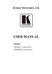
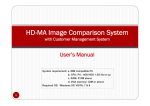
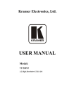
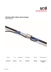
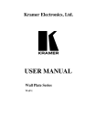
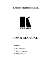
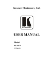
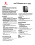
Kramer Electronics, Ltd.
USER MANUAL
Models:
VM-30AV, 1:3 Audio/Video DA
VM-30AVB, 1:3 Audio/Video DA
Contents
Contents
1
2
3
4
5
Introduction
Getting Started
Overview
Your Audio/Video DA
Using Your Audio/Video DA
1
1
1
2
4
6
Technical Specifications
6
5.1
5.2
Connecting a VM-30AV/B
Configuring a 1:3 Audio/Video DA for Component (YUV) or RGB
4
5
Figures
Figure 1: VM-30AV 1:3 Audio/Video DA
Figure 2: VM-30AVB 1:3 Audio/Video DA
Figure 3: VM-30AV 1:3 Audio/Video DA Connection
Figure 4: Configuring a 1:3 Audio/Video DA for Component (YUV) or RGB
2
3
4
6
Tables
Table 1: Front Panel VM-30AV and VM-30AVB 1:3 Audio/Video DA Features
Table 2: Rear Panel VM-30AV and VM-30AVB 1:3 Audio/Video DA Features
Table 3: VM-30AV and VM-30AVB Technical Specifications
3
3
6
i
Introduction
1
Introduction
Dedication by Kramer Electronics since 1981, to the development and
manufacture of high quality video/audio equipment, makes the Kramer line
an integral part of the finest production and presentation facilities in the
world. In recent years, Kramer has redesigned and upgraded most of the line,
making the best even better! The Kramer line of professional video/audio
electronics is one of the most versatile and complete available and is a true
leader in terms of quality, workmanship, price/performance ratio and
innovation.
In addition to our high quality distribution amplifiers, we also offer excellent
switchers and matrices, remote controllers, processors, interfaces and
computer-related products. Congratulations on purchasing your Kramer
VM-30AV and/or VM-30AVB 1:3 Audio/Video DA.
The VM-30AV and/or VM-30AVB are ideal for the following applications:
Video/Audio duplication studios
Retail outlets and home theater systems
The package includes the following items:
VM-30AV and/or VM-30AVB 1:3 Audio/Video DA
Power adapter(s)
This user manual and the Kramer concise product catalog/CD
2
Getting Started
We recommend that you:
Unpack the equipment carefully and save the original box and packaging
materials for possible future shipment
Review the contents of this user manual
3
Overview
The VM-30AV and/or VM-30AVB 1:3 Audio/Video DA are exceptionally
high performance 1:3 distribution amplifiers for video and stereo audio
signals. The VM-30AV and/or VM-30AVB accept one input1 and distribute
the signal to 3 identical outputs. Video signals transmit via:
RCA connectors on the VM-30AV
BNC connectors on the VM-30AVB
1 Typically, a composite video source (such as VCR or camera)
1
Your Audio/Video DA
Both the VM-30AV and/or VM-30AVB include:
RCA connectors for stereo audio signals
Extra wide video bandwidth of 430MHz that allows for high-resolution
data/video signals, SDI (serial digital) video and other specialized signals
An audio level control knob
Front panel cable EQ (equalization) and video level trimmer controls
Achieving the best performance means:
Connecting only good quality connection cables, thus avoiding
interference, deterioration in signal quality due to poor matching, and elevated
noise levels (often associated with low quality cables)
Avoiding interference from neighboring electrical appliances that may
adversely influence signal quality and positioning your Kramer VM-30AV or
VM-30AVB in a location free from moisture and away from excessive
sunlight and dust
4
Your Audio/Video DA
Figure 1 illustrates the front and rear panels of the VM-30AV:
Figure 1: VM-30AV 1:3 Audio/Video DA
2
KRAMER ELECTRONICS, LTD.
Your Audio/Video DA
Figure 2 illustrates the front and rear panels of the VM-30AVB:
Figure 2: VM-30AVB 1:3 Audio/Video DA
Table 1 and Table 2 define the front and rear panels of the VM-30AV and the
VM-30AVB, respectively.
Table 1: Front Panel VM-30AV and VM-30AVB 1:3 Audio/Video DA Features
#
1
2
Feature
POWER Switch
Audio Level Knob
Function
Illuminated switch supplying power to the unit
Adjusts the audio output signal level
3
4
Video EQ. Trimmer
Adjusts1 the video EQ. (equalization) compensation
Video Level Trimmer Adjusts1 the video signal level
Table 2: Rear Panel VM-30AV and VM-30AVB 1:3 Audio/Video DA Features
#
1
2
3
4
5
6
7
Feature
Video INPUT VM-30AV: RCA Connectors
Video OUT
VM-30AVB: BNC Connectors
Audio INPUT (L) RCA Connector
Audio INPUT (R) RCA Connector
Audio OUT (L) RCA Connector
Audio OUT (R) RCA Connector
12 VDC 70mA
Function
Connects to the video source
Connects to the video acceptor (from 1 to 3)
Connects to the left audio source
Connects to the right audio source
Connects to the left audio acceptor (from 1 to 3)
Connects to the right audio acceptor (from 1 to 3)
+12V DC connector for powering the unit
1 Insert a screwdriver into the small hole and carefully rotate it, to trim the appropriate level
3
Using Your Audio/Video DA
5
Using Your Audio/Video DA
Section 5.1 describes how to connect a VM-30AV/B. Section 5.2 describes
how to configure a 1:3 Audio/Video DA for Component (YUV) or RGB. You
can also use the VM-30AV/B, with its very high frequency, to process SDI
(serial digital interface) video.
5.1 Connecting a VM-30AV/B
Connect1 the VM-30AV/B 1:3 Audio/Video DA, as Figure 3 illustrates, as
follows:
1.
Connect a composite video source to the video input connector.
2.
Connect up to 3 video output connectors to the appropriate audio video
acceptors.
3.
Connect the audio source to the right and left audio input connectors.
4.
Connect up to 3 right and left audio output connectors to the appropriate
audio video acceptors.
5.
Connect the 12V DC power adapter to the power socket and connect the
adapter to the mains electricity.
6.
Adjust the audio level and the video EQ. and video level, as required.
Figure 3: VM-30AV 1:3 Audio/Video DA Connection
1 Switch OFF the power on each device before connecting it to your VM-30AV/B. After connecting your VM-30AV/B,
switch on its power and then switch on the power on each device
4
KRAMER ELECTRONICS, LTD.
Using Your Audio/Video DA
5.2 Configuring a 1:3 Audio/Video DA for Component (YUV) or RGB
Configure a 1:3 Audio/Video DA for component (YUV) or RGB by
combining 3 VM-30AV/B units, as Figure 4 illustrates.
Connect1 the 1:3 Audio/Video DA for component (YUV) or RGB, as follows:
1.
Connect the RGB source, by connecting:
The R cable to the first unit’s INPUT connector
The G cable to the second unit’s INPUT connector
The B cable to the third unit’s INPUT connector
2.
Connect the first RGB acceptor, by connecting the OUT 1 connector from
the:
First unit to the R cable
Second unit to the G cable
Third unit to the B cable
3.
Connect the second RGB acceptor, by connecting the OUT 2 connector2
from the:
First unit to the R cable
Second unit to the G cable
Third unit to the B cable
4.
Connect the third RGB acceptor, by connecting the OUT 3 connector
from the:
First unit to the R cable
Second unit to the G cable
Third unit to the B cable
5.
Connect the audio source and acceptors, as required.
6.
On each VM-30AV/B unit, connect the 12V DC power adapter to the
power socket and connect the adapter to the mains electricity.
7.
Adjust the audio level and the video EQ. and video level, as required, on
the front panel on the first VM-30AV/B unit.
This adjusts the levels on the combined 3 VM-30AV/B units.
1 Switch OFF the power on each device before connecting it to your VM-30AV/B units. After connecting your VM-30AV/B
units, switch on the power on each of the VM-30AV/B units and then switch on the power on each device
2 Not illustrated in Figure 4
5
Technical Specifications
Figure 4: Configuring a 1:3 Audio/Video DA for Component (YUV) or RGB
6
Technical Specifications
Table 3 includes the technical specifications.
Table 3: VM-30AV and VM-30AVB Technical Specifications
Inputs:
1 composite video 1 Vpp/75 : RCA connector (VM-30AV); BNC connector (VM-30AVB)
1 stereo audio, 4.8 Vpp / 73k on RCA connectors
Outputs:
3 composite video 1 Vpp/75 : RCA connectors (VM-30AV); BNC connectors (VM-30AVB)
3 stereo audio, 1 Vpp / 150 on RCA connectors
Coupling:
AC
Bandwidth:
Video: 430MHz (-3dB), 370MHz (-0.1dB), Full Load; Audio: >100kHz (-3dB), 20kHz
(-0.1dB)
Gain Range:
Video: -1.1dB to +1.8dB; Audio: -66dB to +16dB
Maximum Output: Video: 2.0Vpp; Audio: 5.4Vpp
Video Equalization: 0 to +14.6dB
S/N Ratio:
Video: 73.1dB; Audio: 83dB
Video Non-linearity: 0.1%
Differential:
Gain: 0.04%; Phase: 0.07 Deg
THD (Audio)/Noise: 0.38% @ 1kHz
2nd Harmonic:
0.02% @ 1kHz
K-Factor:
<0.05%
Dimensions:
16.5cm x 12cm x 4.5cm (6.5” x 4.7” x 1.7”, W, D, H)
Power Source:
12 VDC, 45mA
Weight:
0.6kg (1.3lbs.) approx.
Accessories:
12 VDC power supply
Options:
19" rack adapter RK-50RN kit (holds 2 units in a vertical space of a standard 19” rack)
6
KRAMER ELECTRONICS, LTD.
LIMITED WARRANTY
Kramer Electronics (hereafter Kramer) warrants this product free from defects in material and workmanship under the
following terms.
HOW LONG IS THE WARRANTY
Labor and parts are warranted for three years from the date of the first customer purchase.
WHO IS PROTECTED?
Only the first purchase customer may enforce this warranty.
WHAT IS COVERED AND WHAT IS NOT COVERED
Except as below, this warranty covers all defects in material or workmanship in this product. The following are not covered
by the warranty:
1.
2.
3.
Any product which is not distributed by Kramer, or which is not purchased from an authorized Kramer dealer. If you are
uncertain as to whether a dealer is authorized, please contact Kramer at one of the agents listed in the web site
www.kramerelectronics.com.
Any product, on which the serial number has been defaced, modified or removed.
Damage, deterioration or malfunction resulting from:
i)
Accident, misuse, abuse, neglect, fire, water, lightning or other acts of nature
ii)
Product modification, or failure to follow instructions supplied with the product
iii)
Repair or attempted repair by anyone not authorized by Kramer
iv)
Any shipment of the product (claims must be presented to the carrier)
v)
Removal or installation of the product
vi)
Any other cause, which does not relate to a product defect
vii)
Cartons, equipment enclosures, cables or accessories used in conjunction with the product
WHAT WE WILL PAY FOR AND WHAT WE WILL NOT PAY FOR
We will pay labor and material expenses for covered items. We will not pay for the following:
1.
2.
3.
Removal or installations charges.
Costs of initial technical adjustments (set-up), including adjustment of user controls or programming. These costs are the
responsibility of the Kramer dealer from whom the product was purchased.
Shipping charges.
HOW YOU CAN GET WARRANTY SERVICE
1.
2.
3.
To obtain service on you product, you must take or ship it prepaid to any authorized Kramer service center.
Whenever warranty service is required, the original dated invoice (or a copy) must be presented as proof of warranty coverage,
and should be included in any shipment of the product. Please also include in any mailing a contact name, company, address, and
a description of the problem(s).
For the name of the nearest Kramer authorized service center, consult your authorized dealer.
LIMITATION OF IMPLIED WARRANTIES
All implied warranties, including warranties of merchantability and fitness for a particular purpose, are limited in duration to
the length of this warranty.
EXCLUSION OF DAMAGES
The liability of Kramer for any effective products is limited to the repair or replacement of the product at our option. Kramer
shall not be liable for:
1.
2.
Damage to other property caused by defects in this product, damages based upon inconvenience, loss of use of the product, loss
of time, commercial loss; or:
Any other damages, whether incidental, consequential or otherwise. Some countries may not allow limitations on how long an
implied warranty lasts and/or do not allow the exclusion or limitation of incidental or consequential damages, so the above
limitations and exclusions may not apply to you.
This warranty gives you specific legal rights, and you may also have other rights, which vary from place to place.
NOTE: All products returned to Kramer for service must have prior approval. This may be obtained from your dealer.
This equipment has been tested to determine compliance with the requirements of:
EN-50081:
"Electromagnetic compatibility (EMC);
generic emission standard.
Part 1: Residential, commercial and light industry"
EN-50082:
"Electromagnetic compatibility (EMC) generic immunity standard.
Part 1: Residential, commercial and light industry environment".
CFR-47:
FCC Rules and Regulations:
Part 15: “Radio frequency devices
Subpart B – Unintentional radiators”
CAUTION!
Servicing the machines can only be done by an authorized Kramer technician. Any user who makes changes or modifications to
the unit without the expressed approval of the manufacturer will void user authority to operate the equipment.
Use the supplied DC power supply to feed power to the machine.
Please use recommended interconnection cables to connect the machine to other components.
7
For the latest information on our products and a list of Kramer
distributors, visit our Web site: www.kramerelectronics.com.
Updates to this user manual may be found at
http://www.kramerelectronics.com/manuals.html.
We welcome your questions, comments and feedback.
Kramer Electronics, Ltd.
Web site: www.kramerelectronics.com
E-mail: [email protected]
P/N: 2900–001035 REV 2