1
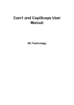
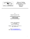
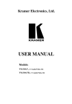
IBS-01e Easy Beauty Scope SKIN & HAIR ANALYSER USER’S MANUAL Version 3, May of 2014 0 USER’S MANUAL Congratulations on your purchase of Easy Beauty Scope. We believe the versatility and ease of use of this product will lead you to obtain more success in business deals and create more profit for you. The Video Microscope is guided cool light surrounding the lens and automatically provides the best illumination to enable you to obtain the optimum viewing angle and colour of the target object on the TV or computer monitor. Image retention on hard copy and image storage are possible by simply connecting the video output of Easy Beauty Scope directly to an optional Color Video Printer, Video Tape Recorder (VTR), or USB output to Personal Computer/ Laptop. 1 1. ACCESSORIES 1-1 Standard accessories: ITEM Q’TY 1 1 Switch box 2 1 Handy probe (with camera resolution:3,000,000 pixels), Probe stand 3 1 AV signal cable (RCA-RCA video cable) 4 1 USB cable, USB driver (CD) & “New KOWA camera” image capture program 5 1 Single frame freeze function (TV connection) 6 1 Power adaptor (100V – 240V) 7 1 User’s Manual DESCRIPTION 1-2 Optional accessories: ITEM DESCRIPTION 1 IBS-01: Lens 1x focus adjustable (for full face/body, half body, partial face) 2 IBS-50: Lens 50x (for skin inspection) 3 IBS-50RN: Lens 50x polarized (for surface/deeper layer skin check) 4 IBS-200: Lens 200x (for hair, scalp inspection) 5 IBS-650: Lens 650x (for hair cuticle inspection) 6 IBS-Iris: Iridology Lens (for iridology analysis) 7 IBS-320: Microcirculation lens 8 IBS-50RN(UV): Lens50x UV polarized (for acne inspection) 9 BX002A Black carrying case 10 Pro Capture software (for history / skin / hair / iris / microcirculation database comparison & customer management system) 11 Kowa Ma software (for skin/ hair image store, before / after comparison & customer management system) 12 Pro Video Master software (for image store, video recording , before / after comparison & customer management system) 2 2. SYSTEM BLOCK DIAGRAM Power adaptor (for connecting to DC input of the unit ) Video output (for RCA Phone jack) connecting to monitor’s video input Freeze button USB port, for PC connection ON OFF Adaptor on Adaptor off When you are connecting the unit with TV, please make sure AV signal cable is connected and use on/off switch to power it ON or OFF. When you are connecting the unit to PC, please make sure USB cable is connected and set the switch to “ON”. 3 3. ATTACHING LENS TO HANDY PROBE 3-1 Attaching lens to handy probe (1) Take off the anti-dust cover of the handy probe (2) Find the short post on the lens Short post (3) Look at the front side of handy probe, you will find there’s a “︵” shape slot. “︵" slot (4) Match (plug in) the post to the “︵” shape slot to ensure they are fully combined. Turn clockwise to screw on the lens, anti-clockwise to screw off the lens. 4 Step 1 Step 3 Step 2 Step 4 3-2 Put handy probe on probe stand 5 4. OPERATION 4-1 Complete the installation in accordance with the system block diagram. Turn the power switches of both the unit and your TV monitor to “ON” position. 4-2 Lens with a contact type illumination head is intended to be placed on or held just above the viewing object, Then you will get a vivid image on the monitor. 5. SINGLE FREEZE FUNCTION OPERATION (TV MODE) Freeze button Mode 1 : Freeze Freeze live picture (Press the freeze button) frozen picture live picture 6 6. OPERATION OF OPTIONAL LENSES (1) 50x Polarized lens You can rotate the black rubber ring anti-clockwise to make surface skin inspection; rotate the black ring clockwise you can make deeper layer skin inspection. Polarized inspection Surface inspection (2) Normal 50x and 200x lens The lens has been well adjusted the focus. You can slightly contact skin or hair for image capture. 50x 200x 7 (3) 1x focus adjustable lens (for styling purpose) The focus range for this lens is adjustable. You can rotate the black ring clockwise or anti-clockwise to get the right focus of full face/body, half body, or partial face). *This lens does not consist any inside LED lamp, therefore getting enough environmental outer light source is required. (4) 650x lens (for hair cuticle inspection) The focus for this lens is adjustable. You can rotate the black ring clockwise or anti-clockwise to get the right focus to inspect the hair cuticle. 8 (5) 50RN(UV) lens This lens is specially designed for ACNE inspection. It needs to be applied under ”Pro Video Master” software. * Under the UV light of 50RN(UV) lens, the acne will appear in fluorescent brown or red color. It is very useful in observation. (6) Iris lens (for iridology analysis) The focus range for this lens is adjustable. You can rotate the black ring clockwise or anti-clockwise to get the right focus of the iris image. Anti-infection cap, please attach it on the top side of the lens. The operation of iris diagnosis. 9 (7) Microcirculation lens --- for observing the thickness, shape of the blood vessels, the speed of blood flow of the nail-tip. (a) Suggested test part: left ring finger, see the picture for available area. Available test area (b) Operation method: Please apply penetrating oil (vegetable oil) on the test part in order to get clearer image. Method 1: Hand hold operation You can hold the handy probe, contact the lens to the available area of left ring finger (Refer to operation in next page) Method 2: Easy stand operation You can also fix the handy probe on a stand, adjust the working distance to get right focus & clear image. 10 320x Microcirculation Lens Application 1. Standard package (1) (3) (2) (4) (1) Finger supporter (Probe stand) 1 pc (2) 320x Microcirculation lens1 pc (3) Empty bottle 1 pc (Please add vegetable oil) (4) Slope plate to adjust finger height 4 pcs ※ Optional: “Pro Video Master program” which gives good image capture & video recording for microcirculation condition observation 2. Usage of Finger supporter Please insert the slope plate in the supporter (If the finger is thicker, the slope plate might be unnecessary.) Put the testing finger inside the supporter 3. Operation of Microcirculation Inspection Please apply vegetable oil on the finger (suggested test part: left ring finger, just near to the nailfold), oil applied area about 1cm2. You can move the testing finger backward & forward to find the best view position. (Ref: 3. Operation of microcirculation inspection) Hold IBS-01e handy probe with 320x lens, contact the lens to the applied area. You can get right focus & clear image by adjusting the probe in a slight slope or moving finger backward & forward 4. The operating position between the operator & the tested 5. Put the handy probe back to probe stand Please hold the handy probe in a parallel direction of the tested finger, then the microcirculation image will be in forward direction to facilitate the microcirculation shape and dynamic observation. * TROUBLE SHOOTING No. TROUBLE SHOOTING 1 The monitor is powered on, but the handy probe doesn’t work (the handy probe cannot offer light or image). 1).Check whether the AC adapter is properly connected. 2).Check if the AV signal cable (or USB cable) is well-connected. 3).Check whether the lens is locked to its right position. (Make sure if the lamps inside the lens is light.) 4).Connect the unit to another monitor to judge the unit or monitor is out of order to repair it. 2 How to clear if there are dust pots on the camera of the handy probe? Take off the lens, you can blow out the dust by using a small air pump or wipe the small glass of the camera (inside the handy probe) with a cotton bar. *Please hold the handy probe toward ground direction to avoid new dusts. If the camera gets mildewed under humid condition, please contact the engineer to clean it. 3 How to adjust when the image color is out of harmony? Please adjust following buttons of the monitor: (1) TINT (2) SHARPNESS (3) BRIGHTNESS (4) COLOR 4 While using the polarized lens to inspect surface skin (or deeper layer skin), why the lower part of the screen becomes darker (or brighter)? It’s because you do not rotate the black rubber ring to the bottom of its direction. So some light is covered (or some light is opened). You should completely rotate the black rubber ring of the polarized lens anti-clockwise (or clockwise). 12 CONNECTION TO PC (I). USB Video Image Driver --- Wbvidcap *System requirement: a. IBM compatible PC b. CPU: P4 with 40G HDD 1.6GHz or up c. RAM: 512M or above *Required OS: Windows XP or Windows VISTA or WIN 7 & 8 1. Installation of Wbvidcap * Remark: Do not connect the scope to PC while USB driver is not well installed. (1) Power on your IBM compatible PC. Insert the USB Driver CD-R into the CD-ROM drive. (2) The CD-R will auto-run Or click “My computer” CD-ROM “Setup.exe”. (3) Click “USB Driver and Application”. (4) Follow the instructions to install the setup program. 13 (4-1): Click “Next”. (4-2): Click “Next”. (4-3): Click “Next”. 14 (4-4): Click “Next”. (4-5): When the setup is finished, PC will automatically execute the next procedure. (4-6): Select “Yes, I want to restart my computer now” and then Click “Finish”. 15 (5) The computer is restarting to add this “Wbvidcap” driver in “PROGRAM” system. (6) To make sure “Wbvidcap” driver is setup, Click “Start” icon → ”All Programs” folder → ”MicroScope” folder → Uninstall Wbvidcap Uninstall Wbvidcap 16 2. Steps of hardware installation (1) Step 1 When the computer is restarted, please connect the scope as per the following instructions and power on the scope: (1-1) Please plug the USB cable one side to scope and the other side to any USB port of the computer. (1-2) Make sure the scope is powered on and wait for 5-10 seconds to let the computer recognize scope signal. (1-3) Please execute the same procedures in step 2 & step 3 to let all computer USB ports useful under scope connection. (2) Step 2 When the computer recognizes the scope signal, monitor screen corner will appear a hint “Find New Hardware Wizard”. After searching for several seconds, there will continuously appear the following small windows. Please operate as per the instructions: 17 Till now, MicroScope Video Capture has also been found. 18 (3) Step 3 Now the MicroScope Video Capture has been found. Please wait for 5 seconds and monitor screen will continuously appear some small windows. Please operate as per the instructions: 19 Till now, MicroScope Bulk Device has also been found. Reminder: Please execute the same procedures in step 2 & step 3 to let all computer USB ports useful under scope connection. 20 3. Connection (Usage) of USB and Beauty Scope When you are using USB cable to connect the Microscope unit and PC, the operation procedures are as follows: 1).Make sure the USB cable has been well connected to USB output of Microscope unit and the USB port of PC. 2).Power on Microscope unit. 3).Click “Start”→ ”All Programs” folder → “MicroScope” folder → “Wbvidcap” Then the image can be observed from PC monitor. A. CONNECTION: A-1 Image size When you are observing the image, the image size is possible to be 640 x 480 or 320 x 240. You can click the “Option” button “Video Format” to change the image size to be your desired 320 x 240 or 640 x 480. (Please refer to the following drawings) 21 Image size: 640 x 480. Image size: 320 x 240. 22 A-2 Video Source selection & Color adjustment If you want to select correct video source or adjust your preferable colorful image, you can click “Option” button --- “Video Source” Video Source selection After clicking “Capture Source”, you should select the correct video capture source to be “MicroScope video Capture”. Click “Apply” and then “OK” and confirm the setting. 23 Color adjustment After clicking “Device Setting”, you can change the brightness, contrast, sharpness, etc. to your desirable value. Click “Apply” and then “OK” and get your desirable color image. If you want to change back to the original color setting, you can just click “Default” and then “OK” to get the original color image. Default B. DISCONNECTION: B-1: If you want to leave “Wbvidcap” operation, close Wbvidcap window firstly and then power off Microscope unit. B-2: If you want to return to AV output, a. Close “Wbvidcap” operation, release the USB connections. b. Complete the AV connection between Microscope unit and TV monitor. c. Re-power on the Microscope unit and the image will be seen from the TV monitor. Notice: When Microscope unit is working with PC under Wbvidcap driver, the output of AV signal will be shut down automatically. 24 (II). TWAIN Driver --- Wcam (only available on 32 bit PC) 1. Why shall we install “WCam” of TWAIN driver? Answer: The original USB driver of this Microscope unit only provides you to get the image picture. If you want to save the picture, you should install “WCam” of TWAIN driver. 2. Installation of WCam. * Remark: a. Please make sure the USB driver of this Microscope unit has been well installed. b. Please do not make any connection between Microscope unit and computer before software installation 2-1. Power on your IBM compatible computer. 2-2. Insert the USB Driver CD-R disk to CD-ROM drive 2-3.Then you can follow the instruction on the USB Driver setup screen to continue the installation process. 2-4. Click on ”TWAIN Driver”. 25 2-5. The program will run automatically. 2-6. Click on “OK” to restart the computer. (To complete the installation, the system must be restarted.) 26 (III). New KOWA camera --- Image capture program * Remark: a. This program can help you to capture and save images. Please make sure the USB driver & TWAIN driver have been well installed. b. Please also connect the USB cable between Microscope unit and computer and power on the unit. c. You can directly click “New KOWA camera” and it will be moved to the main screen (desk) of PC. Now you can go to the main screen (desk) of PC, please double click “New KOWA camera” icon to enter the window. 27 1. As you can see, you can get / freeze image from the window. There are 3 ways to capture image: (a) Press “Enter” . (b) or press “space” key of the keyboard. (c) or press “Freeze” under “Capture” options. 2. When you get / freeze the image, the image will automatically enlarge to as large as the screen height allowed. When you press “Enter”, the image will return to the original size. 28 3. You can also save the image in “jpg” or “bmp” types. 4. Please save the image to your assigned folder and input the file name, and you can also select the original size or max. size to save the image. * Operation under other environments The above is just one of the operation examples under “New KOWA camera” image capture program. If you have other image software (such as Photoshop, PhotoImpact, or Scanner driver software) in your computer, you can also get image and save picture under any image software environment. 29