1
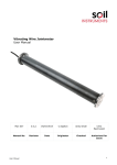
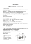
Vibrating Wire Rebar Strain Gauge User Manual Man154 3.0.2 06/08/2014 Kim Malcolm Phil Day Chris Rasmussen Manual No. Revision Date Originator Checked Authorised for Issue User Manual 1 Contents Section 1 : Foreword......................................................................................................................3 Section 2 : Introduction ...............................................................................................................4 Section 3 : Installation .................................................................................................................5 3.01 3.02 3.02.1 3.02.2 3.03 Preliminary Tests ........................................................................................................................... 5 Rebar Strain Gauge Installation ................................................................................................. 5 Model ST5 – 16 to 40 ........................................................................................................................ 5 Model ST5 - 12 “Sister Bar” .............................................................................................................. 7 Cable Installation ........................................................................................................................... 8 Section 4 : Taking Readings ........................................................................................................9 4.01 4.02 Operation of the Vibrating Wire Readout/Logger ................................................................... 9 Measuring Temperatures (Alternative Method) ...................................................................... 9 Section 5 : Data Reduction ........................................................................................................ 10 5.01 5.02 5.03 Strain Calculation ........................................................................................................................10 Temperature Correction .............................................................................................................11 Environmental Factors ................................................................................................................11 Section 6 : Troubleshooting ...................................................................................................... 12 Section 7 : Thermistor Temperature Derivation ................................................................ 14 Section 8 : Data Reduction ........................................................................................................ 16 8.01 Converting from Hz to microstrain ..........................................................................................16 Section 9 : Temperature Effects .............................................................................................. 18 User Manual 2 Section 1 : Foreword Soil Instruments Vibrating Wire Rebar Strain Gauge, as with all our equipment, has been designed to operate consistently in a construction site environment and is, therefore, relatively robust. However, it is essential that the equipment covered by this manual is both operated and maintained by competent and suitably qualified personnel. They must READ AND UNDERSTAND the procedures outlined in this manual before attempting installation or operation of the equipment on site. Soil Instruments will not accept for repair under guarantee, instruments that have been neglected or mishandled in any way. User Manual 3 Section 2 : Introduction Vibrating Wire Rebar Strain Gauges are designed primarily for monitoring the stresses in reinforcing steel in concrete structures, such as bridges, concrete piles and diaphragm walls. The strain meter is comprised of a length of high strength steel, bored along its central axis to accommodate a miniature vibrating wire strain gauge. Readout of load or stress is achieved remotely using a portable readout or datalogging system. The Model ST5 – 16 to 40 Vibrating Wire Rebar Strain Gauge consists of a short length of high strength steel welded between two sections of reinforcing bar. It is designed to be welded between sections of structural concrete reinforcing bar. The cable exits from the strain meter via a compression fitting. See Figure 1. Rebar Strain Gauge Body Stress Gauge Electromagnetic Coil Heat Shrink Thermistor Compression Fitting Instrument Cable Figure 1 - Model ST5 -16 to 40 Rebar Strain Gauge The Model ST5 - 12 Vibrating Wire Rebar Strain Gauge or “Sister Bar” consists of a short length of high strength steel welded between two long sections of reinforcing bar. It is designed to be wire tied in parallel with the structural rebar. The small diameter of the bar minimises its effect on of the sectional modulus of the concrete. The cable exits from the strain meter through a small gland of protective epoxy. See Figure 2. Rebar Strain Gauge Body Stress Gauge Heat Shrink Electromagnetic Coil Thermistor (encapsulated) Protective Epoxy Instrument Cable Figure 2 - Model ST5 - 12 Rebar Strain Gauge Both models of strain meters are robust, reliable and easy to install and read and are unaffected by moisture, cable length or contact resistance. The long term stability of these instruments has proven to be excellent. User Manual 4 Section 3 : Installation 3.01 Preliminary Tests It is always wise, before installation commences, to check the strain meters for proper function. Each strain meter is supplied with a calibration sheet which shows the relationship between readout digits and microstrain and also shows the initial no load zero reading. The strain meter electrical leads (usually the red and black leads) are connected to a readout box (see section 3) and the zero reading given on the sheet is now compared to a current zero reading. The two readings should not differ by more than approx 25 digits after due regard to correction for temperature. Checks of electrical continuity can also be made using an ohmmeter. The resistance between the gauge leads should be approximately 170, ± 10. Remember to add cable resistance when checking (22 AWG stranded copper leads are approximately 14.7/1000’ or 48.5/km, multiply by 2 for both directions). Between the green and white should be approximately 3000 ohms at 25º (see Table B-1) and between any conductor and the shield should exceed 2 megohm. NOTE: Do not lift the strain meter by the cable 3.02 Rebar Strain Gauge Installation 3.02.1 Model ST5 – 16 to 40 The normal procedure is to weld the strain meter in series with the reinforcing steel that is to be instrumented on the site. For a typical installation see Figure 3. The strain meter is long enough so that it may be welded in place without damaging the internal strain gauge element (Figure 1). However, care should still be taken to ensure that the central portion of the strain meter does not become too hot as the plucking coil and protective epoxy could melt. In order to prevent this it may be necessary to place wet rags between the weld area and the coil housing. Also, take care not to damage or burn the instrument cable when welding. After welding, route the instrument cable along the rebar system and tie it off at metre intervals using nylon cable ties. Avoid using iron tie wire to secure the cable as the cable could be cut. Be sure when installing the strain meters to note the location and serial numbers of all instruments. This is necessary for applying the proper calibration factors and determining strain characteristics when reducing data. User Manual 5 Guide Wall Instrument Cables Diaphragm Wall Rebar Strain Meters (2 places, opposite) Rebar Reinforcement Concrete Tieback (installed after excavation) Material to be excavated Rebar Strain Meters (2 places, opposite) Tieback (installed after excavation) Rebar Strain Meters (2 places, opposite) Figure 3 - Model ST5 – 16 to 40 Installation User Manual 6 3.02.2 Model ST5 - 12 “Sister Bar” The “Sister Bar” is usually installed using standard iron tie wire. Normally ties near the ends and at the one third points are sufficient if the gauge is being wired to a larger section of rebar or to horizontal bars. Wiring at the one third points alone is sufficient if the gauge is being wired in parallel to the structural rebar. See Figures 4 and 5. Route the instrument cable along the rebar system and tie it off at metre intervals using nylon cable ties. Avoid using the tie wire on the instrument cable as it could cut the cable. Be sure when installing the strain meters to note the location and serial numbers of all instruments. This is necessary for applying the proper calibration factors and determining load characteristics when reducing date. Instrument Cables Pile Rebar Strain Meters (2 or 3 places) Rebar Reinforcement or Pre-Stressing Cables Concrete Rebar Strain Meters (2 or 3 places) Rebar Strain Meters (2 or 3 places) Figure 4 – ST5 - 12 “Sister Bar” Installation User Manual 7 Instrument Cables Reinforcing Rebar or Strand Instrument Cable Reinforcing Rebar or Strand Wire Tie (2 places) Rebar Strain Meter Rebar Strain Meter (3 places, 120° apart) Wire Tie Tied to Reinforcing Rebar Tied to Reinforcing Rings Figure 5 - Model ST5 - 12 “Sister Bar” Installation Detail 3.03 Cable Installation As noted in the installation sections, route the instrument cables along the structural rebar and tie off using nylon cable ties every 1 metre to secure. Outside of the instrumented structure, the cable should be protected from accidental damage caused by moving equipment or other construction activity. Cables may be spliced to lengthen them, without affecting gauge readings. Always waterproof the splice completely, especially when embedding within the concrete, preferably using an epoxy based splice kit such as Soil Instruments Cable Jointing Kit. User Manual 8 Section 4 : Taking Readings 4.01 Operation of the Vibrating Wire Readout/Logger Connect the Readout using the flying leads or in the case of a Switchable Terminal Unit, with a connector. The red and black conductors are for the vibrating wire gauge, the white and green conductors are for the thermistor. 4.02 Measuring Temperatures (Alternative Method) Each Vibrating Wire Rebar Strain Gauge is equipped with a thermistor for reading temperature. The thermistor gives a varying resistance output as the temperature changes. Usually the white and green leads are connected to the internal thermistor. 1. Connect an ohmmeter to the two thermistor leads coming from the strain meter. (Since the resistance changes with temperature are so large, the effect of cable resistance is usually insignificant). 2. Look up the temperature for the measured resistance in Table B-1. User Manual 9 Section 5 : Data Reduction 5.01 Strain Calculation The basic units utilised by Soil Instruments for measurement and reduction of data from Vibrating Wire Rebar Strain Gauges are Frequency Squared divided by 1000 (F 2/1000) units. Two types of calibration constants and a Thermal Factor are provided on the calibration sheet. The Vibrating Wire Strain Meter is calibrated in kN and the constants calculated for strain/ Equation 1: To reduce F2/1000 units to strain using Linear Factors ųε = G(R1-R0)+K(T1-T0) Where; - G is the Linear Gauge Factor from the calibration sheet R1 is the current F2/1000 reading R0 is the initial (baseline) F2/1000 reading K is the thermal factor T1 is the current temperature in degrees C. T0 is the initial temperature in degrees C. Equation 2: To reduce F2/1000 units to strain using Polynomial Factors ųε = AR12+BR1+C+K(T1-T0) Where; - User Manual A is the A Polynomial Factor from the calibration sheet B is the B Polynomial Factor from the calibration sheet C is the C Polynomial Factor from the calibration sheet R1 is the current F2/1000 reading K is the thermal factor T1 is the current temperature in degrees C. T0 is the initial temperature in degrees C. 10 5.02 Temperature Correction Rebar strain Gauges are usually embedded in concrete and strained by the concrete, the assumption being that the strain in the meter is equal to the strain in the concrete. When the temperature changes, the concrete may expand and contract at a slightly different rate to that of the steel of the vibrating wire. The coefficients of expansion are: Steel: Concrete: Difference (c): 12.2 /º C 10 to 14µ/º C 2.2 to 1.8µ/º C Table 1 Thermal Coefficients Hence a correction is required to the observed strains equal to the difference of these two coefficients. See Equation 3. Equation 3: Thermal Correction ε+C(T1-T0) Where: - ε is the resultant from Equation 1 or 2 To is the initial temperature recorded at the time of installation. T1 is the current temperature. C is the thermal coefficient from Table 1. NOTE: For most practical purposes the temperature effects on the embedded gauges are considered to be the same as those on the concrete. 5.03 Environmental Factors Since the purpose of the strain meter installation is to monitor site conditions, factors which may affect these conditions should be observed and recorded. Seemingly minor effects may have a real influence on the behaviour of the structure being monitored and may give an early indication of potential problems. Some of these factors include, but are not limited to, blasting, rainfall, tidal or reservoir levels, excavation and fill levels and sequences, traffic, temperature and barometric changes, changes in personnel, nearby construction activities, seasonal changes, etc. User Manual 11 Section 6 : Troubleshooting Maintenance and troubleshooting of Vibrating Wire Rebar Strain Gauges are confined to periodic checks of cable connections. Once installed, the meters are usually inaccessible and remedial action is limited. Consult the following list of problems and possible solutions should difficulties arise. Consult the factory for additional troubleshooting help. Symptom: Strain Gauge Readings are Unstable If using a datalogger to record readings automatically, are the swept frequency excitation settings correct? Is there a source of electrical noise nearby? Most probable sources of electrical noise are motors, generators and antennas. Make sure the shield drain wire is connected to ground whether using a portable readout or datalogger. Does the readout work with another strain meter? If not, the readout may have a low battery or be malfunctioning. Symptom: Strain Gauge Fails to Read Is the cable cut or crushed? This can be checked with an ohmmeter. The nominal resistance between the two gauge leads (usually red and black leads) is 170, ± 10. Remember to add cable resistance when checking (22 AWG stranded copper leads are approximately 48.5/km, multiply by 2 for both directions). If the resistance reads infinite or very high (megohms), a cut wire must be suspected. If the resistance reads very low (<20) a short in the cable is likely. Does the readout or datalogger work with another strain meter? If not, the readout or datalogger may be malfunctioning. Symptom: Thermistor resistance is too high Is there an open circuit? Check all connections, terminals and plugs. If a cut is located in the cable, splice according to instructions in Section 2.3. Symptom: Thermistor resistance is too low Is there a short? Check all connections, terminals and plugs. If a short is located in the cable, splice according to instructions in Section 2.3. User Manual 12 User Manual 13 Section 7 : Thermistor Temperature Derivation Thermistor Type: NTC 3000 ohm. Resistance to Temperature Equation: T= 1 A+B(LnR)+C(LnR)3 - 273.2 Equation B-1 Convert Thermistor Resistance to Temperature Where; T = LnR A = B = C = User Manual Temperature in º C = Natural Log of Thermistor Resistance 1.4051 x 10³ (coefficients calculated over the -50 to 150º C span) 2.369 x 10⁻⁴ 1.019 x 10⁻⁷ 14 Ohms 201.1K 187.3K 174.5K 162.7K 151.7K 141.6K 132.2K 123.5K 115.4K 107.9K 101.0K 94.48K 88.46K 82.87K 77.66K 72.81K 68.30K 64.09K 60.17K 56.51K 53.10K 49.91K 46.94K 44.16K 41.56K 39.13K 36.86K 34.73K 32.74K 30.87K 29.13K 27.49K 25.95K 24.51K 23.16K 21.89K 20.70K 19.58K 18.52K 17.53K Temp -50 -49 -48 -47 -46 -45 -44 -43 -42 -41 -40 -39 -38 -37 -36 -35 -34 -33 -32 -31 -30 -29 -28 -27 -26 -25 -24 -23 -22 -21 -20 -19 -18 -17 -16 -15 -14 -13 -12 -11 Ohms 16.60K 15.72K 14.90K 14.12K 13.39K 12.70K 12.05K 11.44K 10.86K 10.31K 9796 9310 8851 8417 8006 7618 7252 6905 6576 6265 5971 5692 5427 5177 4939 4714 4500 4297 4105 3922 3748 3583 3426 3277 3135 3000 2872 2750 2633 2523 Temp -10 -9 -8 -7 -6 -5 -4 -3 -2 -1 0 +1 2 3 4 5 6 7 8 9 10 11 12 13 14 15 16 17 18 19 20 21 22 23 24 25 26 27 28 29 Ohms 2417 2317 2221 2130 2042 1959 1880 1805 1733 1664 1598 1535 1475 1418 1363 1310 1260 1212 1167 1123 1081 1040 1002 965.0 929.6 895.8 863.3 832.2 802.3 773.7 746.3 719.9 694.7 670.4 647.1 624.7 603.3 582.6 562.8 543.7 Temp +30 31 32 33 34 35 36 37 38 39 40 41 42 43 44 45 46 47 48 49 50 51 52 53 54 55 56 57 58 59 60 61 62 63 64 65 66 67 68 69 Ohms 524.4 507.8 490.9 474.7 459.0 444.0 429.5 415.6 402.2 389.3 376.9 364.9 353.4 342.2 331.5 321.2 311.3 301.7 292.4 283.5 274.9 266.6 258.6 250.9 243.4 236.2 229.3 222.6 216.1 209.8 203.8 197.9 192.2 186.8 181.5 176.4 171.4 166.7 162.0 157.6 Temp +70 71 72 73 74 75 76 77 78 79 80 81 82 83 84 85 86 87 88 89 90 91 92 93 94 95 96 97 98 99 100 101 102 103 104 105 106 107 108 109 Ohms 153.2 149.0 145.0 141.1 137.2 133.6 130.0 126.5 123.2 119.9 116.8 113.8 110.8 107.9 105.2 102.5 99.9 97.3 94.9 92.5 90.2 87.9 85.7 83.6 81.6 79.6 77.6 75.8 73.9 72.2 70.4 68.8 67.1 65.5 64.0 62.5 61.1 59.6 58.3 56.8 55.6 Temp +110 111 112 113 114 115 116 117 118 119 120 121 122 123 124 125 126 127 128 129 130 131 132 133 134 135 136 137 138 139 140 141 142 143 144 145 146 147 148 149 150 Table B-1 Thermistor Resistance versus Temperature User Manual 15 Section 8 : Data Reduction 8.01 Converting from Hz to microstrain Data from strain gauges is generally presented in micro strain ( length per unit length:- ) where strain is the ratio of the change in ( ) Practical K factor = 3920 (Gauge calibration constant) Conversion of Period and Linear Units to microstrain is carried out using either of the formulae detailed below:Period Units [ Where ( ) ( ) ] = Change in strain in micro-strain = Gauge Calibration Constant = Base reading in Period units x 107 = Current reading in Period units x 107 Please note: when ( ) ( ) is positive the resultant strain is tensile. Linear Units = Where ( - ) ) = Change in micro-strain = Gauge Calibration Constant = Base reading in units = Current reading in Please note: when ( - units ) is positive the resultant strain is tensile. The calculation of Load in a member using data from strain gauges is often complex. The fundamental problem is determining the composite Young Modulus (E) of the member, since it is often difficult to accurately determine the properties of the insitu materials. Once a Young Modulus is calculated, the following equations can be used to calculate the loading on the structural member at the location of the Strain Gauge. Force (F) = Stress (S) x Area (A) Where A = Cross sectional area in m² Where F units = Newton’s Where S units = N/m² Stress (S) = Young Modulus of Elasticity (E) x Strain ( ) Where E units = N/m² User Manual 16 Example calculation Steel pipe outside diameter = 1.016m Steel pipe inside diameter = 0.984m Calculated change from the strain gauges = 54.688 Young Modulus of Elasticity of the steel pipe = 200,000,000,000 N/m² Stress = E x = 200,000,000,000 x 0.000054688 =10937600 N/m² Area = r² = x (outside diameter /2)² - = x (1.016 /2)² - = x (0.508)² - = x 0.258064 - x (inside diameter /2)² x (0.984 /2)² x (0.492)² x 0.242064 = 0.810732 m² – 0.760466 m² = 0.050266 m² Force = S x A = 10937600 x 0.050266 = 549789.4N User Manual 17 Section 9 : Temperature Effects It is best practice to record temperature when you record strain readings. You can then use the temperature data as well as strain data to analyse the behaviour of the structure. The steel used for the wire in the strain gauge has a thermal coefficient of expansion similar to that of structural steel. Thus, if the gauge and the steel have the same thermal coefficient of expansion and are subjected to the same temperature change, corrections for temperature change are not required. If the gauge is heated by direct sunlight, so that its temperature increases faster than that of the structural steel, you may see large changes in apparent strain. It is difficult to correct for this, so try to shield gauges from direct sunlight using thermally insulated covers. If the steel in the structure has a thermal coefficient that is quite different from that of the gauge, the following temperature correction might be appropriate. corrected = ( ) ( ) Where; is the change in strain, is the thermal coefficient of the member is the thermal coefficient of the gauge:11.0 /°C is the current temperature is the initial temperature Bell Lane, Uckfield, East Sussex t: +44 (0) 1825 765044 e: [email protected] TN22 1QL United Kingdom f: +44 (0) 1825 744398 w: www.itmsoil.com Soil Instruments Ltd. Registered in England. Number: 07960087. Registered Office: 5th Floor, 24 Old Bond Street, London, W1S 4AW User Manual 18