1
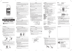
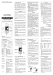
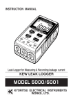
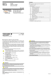
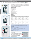
INSTRUCTION MANUAL
DIGITAL PSC-LOOP TESTER
MODEL 4116A, 4118A, 4120A
KYORITSU ELECTRICAL INSTRUMENTS
WORKS,LTD.
CONTENTS
1. SAFE TESTING .............................................................................. 1
2. PROCEDURE OF REMOVING COVER ......................................... 3
3. FEATURES ...................................................................................... 4
3.1 Instrument Layout .................................................................... 4
3.2 Test Lead .................................................................................. 5
3.3 Features ................................................................................... 5
4. SPECIFICATIONS .......................................................................... 7
5. OPERATING INSTRUCTIONS ....................................................... 8
5.1 Initial Checks ............................................................................. 8
5.2 Measurement of the Loop Impedance ...................................... 9
5.3 Measurement of Prospective Short Circuit Current ................. 10
6. DETAILED EXPLANATION ........................................................... 10
6.1 Measurement of Fault Loop Impedance and
Prospective Fault Current ....................................................... 10
6.2 Measurement of OLD-TT System ............................................ 15
6.3 Measurement of Line Impedance and
Prospective Short Circuit Current ............................................ 16
7. SERVICING ................................................................................... 17
8. CASE AND STRAP BELT ASSEMBLY ......................................... 17
1. SAFE TESTING
Electricity is dangerous and can cause injury and death. Always treat it
with the greatest of respect and care. If you are not quite sure how to
proceed, stop and take advice from a qualified person. This instruction
manual contains warnings and safety rules which must be observed by
the user to ensure safe operation of the instrument and retain it in safe
condition. Therefore, read through these operating instructions before
using the instrument.
IMPORTANT:
1. This instrument must only be used by a competent and trained
person and operated in strict accordance with the instructions.
KYORITSU will not accept liability for any damage or injury caused
by misuse or non-compliance with the instructions or with the safety
procedures.
2. It is essential to read and to understand the safety rules contained in
the instructions or with the safety procedures.
3. The symbol
indicated on the instrument means that the user must
refer to the related sections in the manual for safe operation of the
instrument. Be sure to carefully read instructions following each
symbol
in this manual.
DANGER is reserved for conditions and actions that are likely to
cause serious or fatal injury.
WARNING is reserved for conditions and actions that can cause
serious or fatal injury.
CAUTION is reserved for conditions and actions that can cause a
minor injury or instrument damage.
―1―
DANGER
● This instrument is intended only for use in single phase operation
at 230V +10% -15% AC phase to earth or for use in OLD-TT
system phase to neutral.
● When conducting tests do not touch any exposed metalwork
associated with the installation. Such metalwork may become live
for the duration of the test.
● When testing, always be sure to keep your fingers behind the
safety barriers on the test leads.
● Be sure to remove the test lead from the mains power supply
promptly after measurement. Do not leave the instrument
connected to the mains power supply for a long time.
WARNING
● Never open the instrument case - there are dangerous voltages
present. If a fault develops, return the instrument to your distributor
for inspection and repair.
● If the overheat symbol appears in the display (
) disconnect the
instrument from the mains supply and allow to cool down.
● If abnormal conditions of any sort are noted (such as a faulty
display, unexpected readings, broken case, cracked test leads,
etc) do not use the tester and return it to your distributor for repair.
● Never attempt to use the instrument if the instrument or your hand
is wet.
CAUTION
● For those testers without the D-LOK circuitry (models 4116A,
4118A) all RCD's (RCCB, ELCB) in the circuit must be by-passed
for the duration of the test (except on loop-2000Ω range).
Do not operate the RCD Test Button with the RCD by-passed.
● During testing it is possible that there may be a momentary
degradation of the reading due to the presence of excessive
transients or discharges on the electrical system under test.
Should this be observed, the test must be repeated to obtain a
correct reading. If in doubt, contact your distributor.
● Use a damp cloth and detergent for cleaning the instrument. Do
not use abrasives or solvents.
―2―
2. PROCEDURE OF REMOVING COVER
Model 4116A, 4118A and 4120A have a dedicated cover to protect against
an impact from the outside and prevent the operation part, the LCD and the
connector socket from becoming dirty. The cover can be detached and put
on the back side of the main body during measurement.
2.1 Method of removing the cover
Fig. 1
2.2 Method of housing the cover
Fig. 2
―3―
3. FEATURES
3.1 Instrument Layout
⑤
① ②
Wiring correct
(Green LED's)
Reversed L/N terminals
(Red LED)
③
④
Connector
LCD
Fig. 3
1............ LCD display
2............ Wiring check LEDs
3........... Test button
4............ Range switch
5............ Connector
DANGER
● Use original test lead only.
● Max. allowed voltage between mains test terminals and ground is
300V.
● This instrument is intended only for use in single phase operation
at 230V +10% -15% AC phase to earth or for use in OLD-TT
system phase to neutral.
―4―
3.2 Test Lead
The instrument is supplied with Model 7125 lead at socket outlets and Model
7121 distribution board lead.
(1) Model 7125
(2) Model 7121(Included as standard equipment for M-4118A and 4120A. Optional for M-4116A.)
Black-Neutral
Red-Phase
Green-Earth
Fig.4
3.3 Features
3.3-1 Test Range (Function):
Model
D-LOK Circuit *
Loop 0-19.99Ω/
0-199.9Ω/0-1999Ω
PSC 0-199.9A/
0-1999A/0-4.00kA
M-4120A
○
M-4118A
×
M-4116A
×
○
○
○
○
○
×
Note:
● *D-LOK=Automatic device (RCD) lock
● D-LOK dose not operate on the Loop-2000Ω.
● Mains voltage with which D-LOK operates is as shown in the table below.
Range
Loop200Ω/PSC200A
Loop20Ω/PSC2000A, 20kA
D-LOK Operating Voltage
190∼253V
205∼253V
3.3-2 Applied Standards:
Instrument operation:
Safety:
Protection degree:
IEC /EN 61557-1, IEC61557-3
IEC/EN 61010-1 CATⅢ(300V) - instrument
IEC/EN 61010-2-31 CATⅢ(300V) - test lead
IEC60529 (IP 54)
―5―
3.3-3 Model 4116A, 4118A and 4120A have the following features:
● Battery is not used
All models are not battery-operated, but operate by
the voltage supplied from the system.
● Wiring check
Three LEDs indicate if the wiring of the circuit
under test is correct. The P-E and P-N LEDs
illuminate when the wiring polarity of the circuit
under test is correct.
The
Reverse LED is lit when P and N are
reversed.
● Over temperature
Detects overheating of the internal resistor
displaying a warning symbol ( ) and automatically
protection
halting further measurements.
● Overload protection Halts measurement to prevent damages to the
body when voltage between VL-PE is 260V or
more.
"VL-PE Hi" is shown on the display.
● D-LOK circuit
Model 4120A with unique D-LOK circuit avoids the
need to by-pass most RCD's.
● 15mA Loop
Loop impedance 2000Ω range measurement is
carried out with low test current (15mA). The
measurement
current will not cause tripping out involved RCD
even the one with the lowest nominal differential
current (30mA).
● Display
The liquid crystal display has 3 1/2 digits with a
decimal point and units of measurement (Ω, A,
kA,V).
● Manual and Autotest mode
Manual − Press and release the "Press to Test" button. The result will be
displayed for 3s and then the display will revert to AC voltage.
Autotest − The "Press to Test" button can be turned clockwise to lock it
down. In this auto mode, when using distribution board lead
M-7121, tests are conducted by simply disconnecting and
reconnecting the red phase prod of the M-7121 avoiding the
need to physically press the test button i.e. "hands free".
CAUTION
● The D-LOK circuits may not by-pass some RCD's and this will
result in the RCD tripping out as they would do with a conventional
loop tester. Also, in the case of high sensitivity RCD's rated at
10mA or less the D-LOK circuits may not function.
―6―
4. SPECIFICATIONS
● Measurement Specification
Loop Impedance ( IEC61557-3)
Range
20Ω
200Ω
2000Ω
Measuring range
0.00∼19.99Ω
0.0 ∼199.9Ω
0 ∼1999Ω
Nominal test current
at 0Ω external loop
25A / 20ms
2.3A / 40ms
15mA /280ms
Accuracy
±(2%rdg + 4dgt)
Prospective Short-circuit Current (M-4118A, M-4120A)
Nominal test current
Range
Accuracy
Measuring range
at 0Ω external loop
2.3A / 40ms
200A
0.0 ∼199.9A
Consider accuracy
25A / 20ms
2000A
0 ∼1999A
of Loop Impedance
25A / 20ms
20kA
0.00 ∼ 4.00kA
Voltage
Measuring range
110 ∼ 260V
Instrument dimensions
Instrument weight
Reference conditions
Operating temperature
and humidity
Storage temperature
and humidity
Symbols used on the
instrument
Accuracy
±(2%rdg + 4dgt)
186×167×89mm
M-4120A / 960g, M-4116A and M-4118A / 750g
Specifications are based on the following conditions
except where otherwise stated:
1. Ambient temperature: 23 ± 5 ℃
2. Relative humidity:45% to 75%
3. Position: horizontal
4. AC power source: 230V, 50Hz
5. Altitude: Up to 2000m
0 to +40℃, relative humidity 80% or less, no
condensation.
−20 to +60℃, relative humidity 75% or less, no
condensation.
Equipment protected throughout by DOUBLE
INSULATION or REINFORCED INSULATION.
Caution(refer to accompanying instruction
manual)
―7―
● Operating Error of Loop Impedance (61557-3)
Measuring range to keep
Maximum percentage
operating error
operating error
20Ω
0.20 ∼ 19.99Ω
200Ω
±30%
20.0 ∼ 199.9Ω
2000Ω 200 ∼ 1999Ω
The influencing variations used for calculating the operating error are
denoted as follows:
Temperature:0℃ and 40℃
Phase angle :At a phase angle 0゜to 18゜
System frequency:49.5Hz to 50.5Hz
System voltage:230V+10%-15%
Range
5. OPERATING INSTRUCTIONS
5.1 Initial Checks - To be carried out before any testing.
(1) Test Lead Connection
Insert the lead plug into the connector on the instrument correctly as
shown below.
Lead Plug
Fig. 5
CAUTION
● Always inspect your test instrument and lead accessories for
abnormality or damage. If abnormal conditions exist DO NOT
PROCEED WITH TESTING.
(2) Wiring Check
Before pressing the "Test Button" always check the LED's for the
following sequence:
P-E Green LED must be ON
P-N Green LED must be ON
Red LED must be OFF
―8―
WARNING
● If the above sequence is NOT displayed or the RED LED is on for
any reason , DO NOT PROCEED AS THERE IS INCORRECT
WIRING. The cause of the fault must be investigated and rectified.
(3) Voltage Measurement
When the instrument is first connected to the system, it will display the
phase-neutral voltage which is updated every 1s. This mode is cancelled
whenever the test button is pressed. If this voltage is not normal or as
expected, DO NOT PROCEED.
WARNING
● This instrument is intended only for use in single phase operation
at 230V +10% -15% AC phase to earth or for use in OLD-TT
system phase to neutral.
5.2 Measurement of the Loop Impedance
(1) Set the instrument to the 200Ω or 2000Ω range.
If the instrument is set to the 20Ω range slight sparking may occur
when testing with the distribution board lead although the unit has
been designed to minimize this.
(2) Connect the lead to the instrument.
(3) Plug the moulded mains plug to the socket being tested.
(4) Check the LED's are lit as indicated in section 5.1. If not DO NOT
PROCEED - check wiring.
(5) Note the mains voltage if required.
(6) Press the "Press to Test" button. The value of loop impedance will be
displayed with the appropriate units. A bleep will sound on completion
of the test.
For best results always test on the lowest possible range.
For example, a loop impedance measured on the 200Ω range may
give an indication of 0.3Ω whereas on the 20Ω range it may read 0.28
Ω. In the event of the reading being in excess of the range (e.g. more
than 20Ω on the 20Ω range) the appropriate over-range symbol "OL"
will appear on the display.
No harm will be done to the instrument by selecting too low a range.
―9―
5.3 Measurement of Prospective Short Circuit Current
− (Models 4118A and 4120A)
(1) Set the instrument to the 20kA range.
(2) Connect the test lead to the instrument.
(3) Attach the plug to the socket to be tested.
(4) Check that the LED's are lit in the sequence indicated in section 5.1. If
not, disconnect from the mains and check the wiring at the socket.
(5) Press the "Press to Test" button. The prospective short circuit current
(PSC) will be directly displayed on the LCD with the appropriate units.
This will remain for 3s and then revert to AC voltage display.
An audible beep will sound on completion of the test. For best results
always test on the lowest possible range.
For example a PSC measured on the 2000A range may read 60A
whilst on the 200A range it may read 56.0A. To hold the reading keep
the button held down or turn clockwise to lock for Auto Test.
Note:
● For loop impedance greater than 210Ω on PSC 200A range and 25
Ω on 2000A, 20kA ranges, the fault voltage may become high and
dangerous due to the D-LOK current, therefore, the unit is designed
to lock out PSC ranges showing "Uf-Hi" symbol.
Normally PSC tests are conducted at point of origin, e.g. distribution boards,
between phase and neutral.
When conducting PSC tests at socket outlets, a test will be conducted
between phase and earth due to the fixed wiring of the moulded mains plug.
WARNING
● This instrument is intended only for use in single phase operation
at 230V +10% -15% AC phase to earth or for use in OLD-TT
system phase to neutral.
6. DETAILED EXPLANATION
6.1 Measurement of Fault Loop Impedance and Prospective Fault Current
If the electrical installations are protected by over-current protection
devices or by fuses, the Fault loop impedance should be measured.
― 10 ―
In the event of a fault, the Fault loop impedance should be low enough
(and the Prospective Fault current higher enough) in order to have the
automatic disconnection of supply by the installed protection device within
prescribed time interval.
Every circuit must be tested to make sure that the fault loop impedance
does not exceed that specified for the over current protection device
concerned.
For TT system the Fault loop impedance is the sum of the following partial
impedances:
¡ Impedance of power transformer's secondary.
¡ Phase conductor resistance from power transformer to fault location.
¡ Protection conductor resistance from fault location to local earth
system.
¡ Resistance of local earth system R.
¡ Resistance of power transformer's earth system Ro.
The figure below shows in marked line the Fault loop impedance for TT
system.
Fig.6
For TN system the Fault loop impedance is the sum of the following partial
impedances:
¡ Impedance of power transformer's secondary
¡ Phase conductor resistance from power transformer to fault location
¡ Protection conductor resistance from fault location to power transformer
― 11 ―
The figure below shows in marked line the Fault loop impedance for TN
system.
Fig.7
According to the international Standard IEC 60364 for TT system the
following condition shall be fulfilled for each circuit:
RA<50/Ia
Where:
¡ RA is the sum of the resistances of the local earth system R and
protection conductor connecting it to the exposed conductive part.
¡ 50 is the max contact voltage limit (it could be 25V in particular cases)
¡ Ia is the current causing the automatic disconnection of the protective
device within 5 s.
When the protection device is a residual current device (RCD), Ia is the rated
residual operating current I ⊿ n.
For instance in a TT system protected by a RCD the max RA values are:
Rated residual operating current I⊿n.
RA (at 50V)
RA (at 25V)
10
5000
2500
30
1667
833
100
500
250
300
167
83
500
100
50
1000
50
25
mA
Ω
Ω
Note:
● The loop tester models 4120A / 4118A / 4116A measure the fault
loop impedance that is a value normally a little bit higher of RA.
But, if the electrical installation is protected considering the loop
impedance value, also the RA formula will be fulfilled.
― 12 ―
Practical example of verification of the protection in a TT system according
to the international Standard IEC 60364.
RCD 30mA
RO
L1
L2
L3
N
PE
R
Fig.8
For this example max value is 1667Ω, the loop tester reads 12.74Ω, it
means that the condition RA<50/Ia is respected.
It is fundamental for this example to test also the RCD to ensure that
operation takes place quickly enough to respect the safety requirements. In
order to do it, can be used the RCD tester model 5406A.
According to the international Standard IEC 60364 for TN system the
following condition shall be fulfilled for each circuit:
Zs<Uo/Ia
Where:
¡ Zs is the Fault loop impedance.
¡ Uo is the nominal voltage between phase to earth.
¡ Ia is the current causing the automatic disconnection of the protective
device within the time stated in table as follows:
Uo (Volts)
120
230
400
>400
T (seconds)
0.8
0.4
0.2
0.1
Note:
● For a distribution circuit a disconnection time not exceeding 5s is
permitted.
● When the protection device is a residual current device (RCD), Ia is
the rated residual operating current I⊿n.
― 13 ―
For instance in a TN system with nominal mains voltage Uo = 230 V
protected by gG fuses the Ia and max Zs values could be:
Rating
(A)
6
10
16
20
25
32
40
50
63
80
100
Disconnecting time 5s Disconnecting time 0.4s
Ia (A)
Zs (Ω)
Ia (A)
Zs (Ω)
28
8.2
47
4.9
46
5
82
2.8
65
3.6
110
2.1
85
2.7
147
1.56
110
2.1
183
1.25
150
1.53
275
0.83
190
1.21
320
0.72
250
0.92
470
0.49
320
0.71
550
0.42
425
0.54
840
0.27
580
0.39
1020
0.22
Using the current ranges on models 4120A and 4118A can be also tested
the Prospective Fault current.
Prospective Fault current measured by instruments must be higher than Ia
of the protective device concerned
Practical example of verification of the protection in a TN system according
to the international Standard IEC 60364.
Fuse gG 16A
RO
Fig.9
― 14 ―
L1
L2
L3
N
PE
Max value of Zs for this example is 2.1Ω (16A gG fuse, 0.4s) the loop tester
reads 1.14Ω (or 202 A on Fault current range) it means that the condition Zs
<Uo/Ia is respected.
In fact the Zs of 1.14Ω is less than 2.1Ω (or the Fault current of 202 A is
more than Ia of 110A).
WARNING
● This instrument is intended only for use in single phase operation
at 230V +10% -15% AC phase to earth or for use in OLD-TT
system phase to neutral.
● If the overheat symbol appears in the display (
) disconnect the
instrument from the mains supply and allow to cool down.
6.2 Measurement of "OLD-TT System"
OLD-TT system is a TT system with phase to phase voltage of 220 V
(instead of 400 V) and phase to earth of 127 V (instead of 230V) and
normally the neutral conductor is not used.
Connecting the loop testers to this system, all three wiring check LEDs
should be lit and the display reads a value of 127 V.
Only if all these conditions are respected the test can be carry out.
RCD 30mA
L1
L2
L3
PE
RO
R
Fig.10
― 15 ―
220V
220V
220V
WARNING (OLD-TT system only)
● DO NOT PRESS the "Test button" if the display reads a value of
220V!
The RCD could trip during the tests also with model 4120A.
CAUTION
● The D-LOK circuit of 4120A can not works with 127V between
phase to earth.
6.3 Measurement of Line Impedance and Prospective Short Circuit Current
Line Impedance on single-phase system is the impedance measured
between phase and neutral terminals.
Measurement principle used inside the instrument is exactly the same as at
Fault Loop Impedance measurement, but the measurement is carried out
between L and N terminals.
Breaking current capacity of installed over-current protection devices should
be higher than Prospective Short-Circuit current, otherwise it is necessary to
change the rated current of involved over-current protection device.
Practical example of line impedance test and prospective short-circuit
current test (only for models 4120A and 4118A):
The figure below shows in marked line the Line impedance phase to neutral
for TN system.
RCD
L1
L2
L3
N
PE
L
PE
N
RO
Fig.11
― 16 ―
WARNING
● This instrument is intended only for use in single phase operation
at 230V +10% -15% AC phase to earth or for use in OLD-TT
system phase to neutral.
● If the overheat symbol appears in the display (
) disconnect the
instrument from the mains supply and allow to cool down.
● When testing installation that has a large current capacity, such as
a power line, be sure not to short live conductors with the tip of a
probe. Failure to follow these instruction can cause hazards to the
user.
7. SERVICING
If this tester should fail to operate correctly, return it to your distributor stating
the exact nature of the fault.
Please remember to give all the information possible concerning the nature
of the fault, as this will mean that the instrument will be serviced and
returned to you more quickly.
8. CASE AND STRAP BELT ASSEMBLY
Correct assembly is shown in Fig 12. By hanging the instrument round the
neck, both hands will be left free for testing.
Pass the strap belt down
through the side panel of the
main body from the top, and up
through the slots of the probe
case from the bottom.
Fig.12
― 17 ―
Pass the strap through the
buckle, adjust the strap for
length and secure.
DISTRIBUTOR
92-1483
01-05
Kyoritsu reserves the rights to change specifications or designs
described in this manual without notice and without obligations.
R
KYORITSU ELECTRICAL
INSTRUMENTS
WORKS, LTD.
No.5-20, Nakane 2― chome, Meguro-ku,
Tokyo, 152-0031 Japan
Phone:
(03)
3723― 0131 Telex:0246― 6703
Fax:
(03)
3723― 0152
Cable Address:"KYORITSUKEIKI"TOKYO
URL:http://www.kew-ltd.co.jp
E-mail:[email protected]
Factories:Uwajima&Ehime