1
3.2. EMBEDDED SYSTEM DESIGN PROCESS
55
Let’s take a closer look at each of these. The information provided here is an abbreviated
version of the one provided in “Microcontrollers Fundamentals for Engineers and Scientists.” The
interested reader is referred there for additional details and an indepth example [Barrett and Pack].
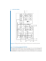
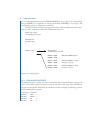
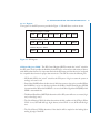
Top down design, bottom up implementation. An effective tool to start partitioning the
design is based on the techniques of top-down design, bottom-up implementation. In this approach,
you start with the overall system and begin to partition it into subsystems. At this point of the design,
you are not concerned with how the design will be accomplished but how the different pieces of
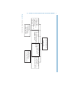
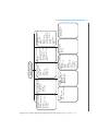
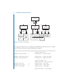
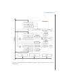
the project will fit together. A handy tool to use at this design stage is the structure chart. The
structure chart shows the hierarchy of how system hardware and software components will interact
and interface with one another. You should continue partitioning system activity until each subsystem
in the structure chart has a single definable function.
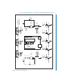
UML Activity Diagram. Once the system has been partitioned into pieces, the next step
in the design process is to start working out the details of the operation of each subsystem we
previously identified. Rather than beginning to code each subsystem as a function, we will work out
the information and control flow of each subsystem using another design tool: the Unified Modeling
Language (UML) activity diagram. The activity diagram is simply a UML compliant flow chart.
UML is a standardized method of documenting systems. The activity diagram is one of the many
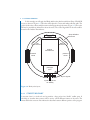
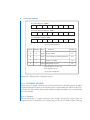
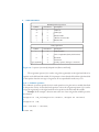
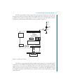
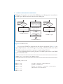
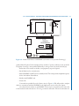
tools available from UML to document system design and operation. The basic symbols used in a
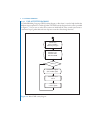
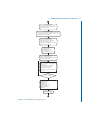
UML activity diagram for a microcontroller based system are provided in Figure 3.2[Fowler].
Starting
Activity
Branch
Transfer
of Control
Final State
Action State
Figure 3.2: UML activity diagram symbols. Adapted from [source].