1
28
I/O SERVER User’s Manual
Industrial PC
__________________________________________________________________
4.0 SYSTEM
OVERVIEW
WARNING: Per specifications,
only the USB ports are
switchable while power is
applied to the system.
I/O Server Internal Ethernet
Switch
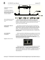
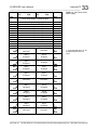
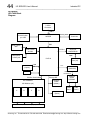
This Section provides information regarding system design and
operating information for the I/O Server. Reference the block diagram
below as you read this material.
The I/O Server has an embedded Intel N270 1.6GHz CPU. Intel
chipsets 946GSE and ICH7M are used for I/O and memory interfaces. The
board supports up to 1GB of 533/667MHz DDR2 in a SODIMM socket.
The I/O Server has an integrated graphics engine Intel GMA950 with
support for Microsoft DirectX 9.1 Additional interfaces include VGA, AC97
audio, 10/100 LAN, PCI Bus, Primary IDE Bus, four USB Ports, two Serial
ports. Support circuitry is provided for all of these interfaces. None of the
I/O Connectors on the I/O Server are isolated (i.e. connector and power
logic commons have a direct electrical connection).
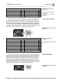
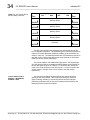
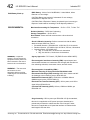
The I/O Server has an internal 10/100 “unmanaged” Ethernet Switch.
This switch is designed to work automatically right out of the box with no
special programming or setup. The standard settings for the switch are
described in the table below. This is a three port switch. One port is
connected to the processor unit. The operating system of the I/O Server
will always detect a minimal connection to an Ethernet port. The remaining
two ports are connected to the external RJ45 jacks on the Front Panel of
the I/O Server. Due to this internal switch, the bandwidth from the I/O
Server processing unit to the Field is the same as a single Ethernet port.
BASIC (DEFAULT) DEVICE OPERATION
Automatic MDI/MDI-X.
Automatic Polarity.
Automatic Half/Full Duplex.
Automatic 10M/100M.
Automatic Address Learning.
Automatic Address Migration.
Automatic Address Aging using 5 minute period (300±75s).
Flow Controls Enabled.
Half-Duplex Back Pressure Applies.
Standard Half-Duplex Back-Off Applies.
Switch will check that frame length conforms to maximum size limit.
Yellow LED indicate Speed 100M ON/10M OFF
Green LED indicate Link ON/Activity Blinking
I/O Server Power Supply
Fuse
The 9V to 32V DC supply lines to the I/O server is fused with a current
limit of 10 Amps. The fuse is a standard 3AG size. A blown fuse can be
identified by non-functional power status LED. The fuse on the
motherboard is not easily accessible. An external fuse or current limiting
power supplied is recommended. Acromag’s PS5R-S line of isolated
AC/DC power supplies work well for this application. Contact Acromag for
further information.
IDE (PATA) – Hard Drive
Connections
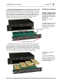
The Primary IDE (or PATA) hard drive interface along with power is
®
physically routed on the PCB boards to both the CompactFlash and
optional 2.5” drive. This approach removes any internal cables and the
inherent disadvantages associated with them such as lower shock and
®
vibration tolerance. The CompactFlash slot is hard-wired as the Primary
IDE Master. Therefore to prevent contention the optional 2.5” drive must
always be set as a Slave (via jumpers) prior to installation. To prevent
________________________________________________________________________
Acromag, Inc. Tel:248-295-0310 Fax:248-624-9234 Email:[email protected] http://www.acromag.com