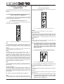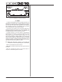
1
Version 1.1 November 2001 www.behringer.com ENGLISH OPERATING MANUAL SAFETY INSTRUCTIONS DETAILED SAFETY INSTRUCTIONS: All the safety and operation instructions should be read before the appliance is operated. Retain instructions: The safety and operating instructions should be retained for future reference. Heed warnings: All warnings on the appliance and in the operating instructions should be adhered to. CAUTION: WARNING: To reduce the risk of electric shock, do not remove the cover (or rear). No user serviceable parts inside; refer servicing to qualified personnel. To reduce the risk of fire or electric shock, do not expose this appliance to rain and moisture. This symbol, wherever it appears, alerts you to the presence of uninsulated dangerous voltage inside the enclosure—voltage that may be sufficient to constitute a risk of shock. This symbol, wherever it appears, alerts you to important operating and maintenance instructions in the accompanying literature. Please, read the manual. Follow instructions: All operation and user instructions should be followed. Water and moisture: The appliance should not be used near water (e. g. near a bathtub, washbowl, kitchen sink, laundry tub, in a wet basement, or near a swimming pool, etc.). Ventilation: The appliance should be situated so that its location or position does not interfere with its proper ventilaton. For example, the appliance should not be situated on a bed, sofa rug, or similar surface that may block the ventilation openings: or placed in a built-in installation, such as a bookcase or cabinet that may impede the flow of air through the ventilation openings. Heat: The appliance should be situated away from heat sources such as radiators, heat registers, stoves, or other appliances (including amplifiers) that produce heat. Power source: The appliance should be connected to a power supply only of the type described in the operating instructions or as marked on the appliance. Grounding or polarization: Precautions should be taken so that the grounding or polarization means of an appliance is not defeated. Power-cord protection: Power supply cords should be routed so that they are not likely to be walked on or pinched by items placed upon or against them, paying particular attention to cords and plugs, convenience receptacles and the point where they exit from the appliance. Cleaning: The appliance should be cleaned only as recommended by the manufacturer. Non-use periods: The power cord of the appliance should be unplugged from the outlet when left unused for a long period of time. Object and liquid entry: Care should be taken so that objects do not fall and liquids are not spilled into the enclosure through openings. Damage requiring service: The appliance should be serviced by qualified service personnel when: s the power supply cord or the plug has been damaged; or s objects have fallen, or liquid has been spilled into the appliance; or s the appliance has been exposed to rain; or s the appliance does not appear to operate normally or exhibits a marked change in performance; or s the appliance has been dropped, or the enclosure damaged. Servicing: The user should not attempt to service the appliance beyond that which is described in the operating instructions. All other servicing should be referred to qualified service personnel. 2 FOREWORD Dear Customer, Welcome to the team of DDX3216 users, and thank you very much for expressing your confidence in BEHRINGER products by purchasing the DDX3216. It is one of my most pleasant tasks to write this letter to you, because it is the culmination of many months of hard work delivered by our engineering team to reach a very ambitious goal: To produce a digital mixer, which fully satisfies your and our expectations and delivers a superior sound quality, easy operation and technical specifications. The task to design the DDX3216 certainly meant a great deal of responsibility, which we assumed by focusing on you, the discerning user and musician. It also meant a lot of work and night shifts to accomplish this goal. But it was fun, too. Developing a product usually brings a lot of people together, and what a great feeling it is when everybody who participated in such a project can be proud of what we’ve achieved. It is our philosophy to share our joy with you, because you are the most important member of the BEHRINGER family. With your highly competent suggestions for new products you’ve greatly contributed to shaping our company and making it successful. In return, we guarantee you uncompromising quality (manufactured under ISO9000 certified management system) as well as excellent technical and audio properties at an extremely favorable price. All of this will enable you to fully unfold your creativity without being hampered by budget constraints. We are often asked how we manage to produce such highgrade devices at such unbelievably low prices. The answer is quite simple: it’s you, our customers! Many satisfied customers means large sales volumes enabling us to get better conditions of purchase for components, etc. Isn’t it only fair to pass this benefit back to you? Because we know that your success is our success, too! I would like to thank the following people, whose help on “Project DDX3216” has made it all possible: s all BEHRINGER users who made valuable contributions with their suggestions and ideas; s Joost, Jean, Jos, Jörg, Thomas and Christian whose passionate work made the DDX3216 a really out-of-theordinary digital mixing console; s Thorsten and Markus who designed this excellent manual; s Ina and Volker for the sophisticated mechanics; s everybody who contributed with great enthusiasm to this project. My friends, it’s been worth the trouble. Thank you very much, Uli Behringer CAUTION! + Please note that extreme volume levels can damage your hearing and/or headphones. Be sure to use appropriate volumes levels. 3 Ultra-flexible, automated 32-channel 16-bus digital mixing console s State-of-the-art 32-channel digital mixing console with 16 internal busses and 8 aux sends for extreme routing flexibility s High-power floating point DSP technology ensures virtually unlimited internal dynamic range s Ultra high-resolution 24-bit AKM® A/D and CRYSTAL® D/A converters s 12 ULN (Ultra Low-Noise) microphone inputs with analog inserts and switchable phantom power s 4-band fully parametric equalizer, low-cut filter, gate, compressor and phase inverter on all 32 channels with additional delay function on the first 16 channels s Four built-in effects processors with first-class algorithms, such as reverb, chorus, flanger, phaser, delay, pitch shifter, tremolo, lo-fi, LFO filter, ring modulator and more s 17 ultra-precise, low-noise 100-mm motorized ALPS® faders s Freely configurable built-in level meters on all channels and channel controls with LED rings, which control any of nine selectable parameters per channel s Fully-featured static and dynamic automation functions s Four freely assignable analog outputs on balanced 1/4" TRS connectors s Internal input/output patchbay for easy routing of complex signal configurations s Six master controllers for comfortable push-and-turn functionality s Large, easy-to-read LCD display with adjustable contrast s Synchronization to SMPTE, MTC or internal clock s Dither, word length and noise shaping adjustable for digital main outputs s Two slots for installation of optionally available digital interfaces based on AES/EBU (8 I/O), ADAT® (16 I/O) or TDIF formats (16 I/O) s MIDI and RS232 connectors allow communication with a PC or numerous other devices s Extensive MIDI implementation (MMC, program changes, control changes, MIDI sysex) s PC card slot for saving/loading various libraries and other settings s Free PC software for data transmission and management downloadable at www.ddx3216.com (serial cable included) s 19" rack-mounting kit included s Manufactured under ISO9000 certified management system 4 BLOCK DIAGRAM 5 TABLE OF CONTENTS 1. INTRODUCTION ....................................................................................................... 10 1.1 Digital vs. analog ............................................................................................................................................. 10 1.2 Concept ............................................................................................................................................................ 10 1.2.1 Architecture ........................................................................................................................................ 10 1.2.2 Design concept and componentry .................................................................................................... 11 1.2.3 Open architecture .............................................................................................................................. 11 1.3 Before you begin .............................................................................................................................................. 11 1.3.1 Shipment ........................................................................................................................................... 11 1.3.2 Initial operation .................................................................................................................................. 11 1.3.3 Warranty ............................................................................................................................................. 11 2. CONTROL ELEMENTS AND CONNECTORS ........................................................ 12 2.1 Connection interfaces and control elements on the top side of the DDX3216 .............................................. 12 2.1.1 Microphone and line inputs 1-12 ...................................................................................................... 12 2.1.2 Line inputs 13 to 16 ........................................................................................................................... 12 2.1.3 Phantom power and 2-track inputs/outputs ..................................................................................... 12 2.1.4 Control room and phones sections .................................................................................................. 13 2.2 The rear panel of the DDX3216 ....................................................................................................................... 13 2.2.1 Control room, multi and main outputs .............................................................................................. 13 2.2.2 Digital S/PDIF and wordclock inputs/outputs ................................................................................... 13 2.2.3 SMPTE and RS232 inputs ................................................................................................................ 13 2.2.4 MIDI connections ............................................................................................................................... 14 2.2.5 Power supply and fuse ...................................................................................................................... 14 2.2.6 Option slots 1 and 2 .......................................................................................................................... 14 2.3 PCMCIA card slot ............................................................................................................................................. 14 2.4 Channels and main mix .................................................................................................................................. 14 2.4.1 Channel strips ................................................................................................................................... 14 2.4.2 Main Mix ............................................................................................................................................. 15 2.5 Display ............................................................................................................................................................. 16 2.6 Snapshot automation: switches and displays ................................................................................................ 16 2.7 Left switch block .............................................................................................................................................. 16 2.7.1 Fader bank ........................................................................................................................................ 16 2.7.2 Channel control bank ........................................................................................................................ 17 2.7.3 Proc(ess) bank .................................................................................................................................. 17 2.7.4 General bank ..................................................................................................................................... 17 2.7.5 Auto(mation) bank ............................................................................................................................. 18 3. DIGITAL CHANNEL PROCESSING ......................................................................... 18 3.1 CHANNEL LIBRARIES ..................................................................................................................................... 18 3.2 CHANNEL PROCESSING switches ................................................................................................................ 19 3.3 A/B function ...................................................................................................................................................... 19 3.4 Equalizer .......................................................................................................................................................... 19 3.4.1 EQ menu page .................................................................................................................................. 19 3.4.2 HIGH PASS menu page .................................................................................................................... 19 3.4.3 EQ LIBRARY menu page .................................................................................................................. 19 3.4.4 EQ parameters .................................................................................................................................. 19 3.5 Dynamics processing ..................................................................................................................................... 20 3.5.1 GATE menu page .............................................................................................................................. 20 3.5.2 COMP(RESSOR) menu page ........................................................................................................... 20 3.5.3 Compressor parameters .................................................................................................................. 20 3.5.4 DYNAMICS LIBRARY menu page ..................................................................................................... 21 3.6 DELAY menu .................................................................................................................................................... 21 4. CHANNEL ROUTING AND BUSSES ...................................................................... 22 4.1 Channel routing ............................................................................................................................................... 22 4.2 Multi-track bus faders ...................................................................................................................................... 22 4.3 Aux and FX sends ............................................................................................................................................ 22 6 5. EFFECTS PROCESSORS ....................................................................................... 24 5.1 FX menu ........................................................................................................................................................... 24 5.1.1 Selecting an effect algorithm ............................................................................................................. 24 5.2 Editing effect algorithms .................................................................................................................................. 24 5.2.1 Cathedral ........................................................................................................................................... 24 5.2.2 Plate ................................................................................................................................................... 24 5.2.3 Small Hall .......................................................................................................................................... 25 5.2.4 Room ................................................................................................................................................. 25 5.2.5 Concert .............................................................................................................................................. 25 5.2.6 Stage ................................................................................................................................................. 26 5.2.7 Spring Reverb .................................................................................................................................... 26 5.2.8 Gated Reverb ..................................................................................................................................... 26 5.2.9 Stereo Delay ...................................................................................................................................... 27 5.2.10 Echo ................................................................................................................................................. 27 5.2.11 Stereo Chorus ................................................................................................................................. 27 5.2.12 Stereo Flanger ................................................................................................................................. 27 5.2.13 Stereo Phaser ................................................................................................................................. 28 5.2.14 Pitch Shifter ..................................................................................................................................... 28 5.2.15 Delay ................................................................................................................................................ 28 5.2.16 Flanger ............................................................................................................................................ 28 5.2.17 Chorus ............................................................................................................................................. 28 5.2.18 Phaser ............................................................................................................................................. 29 5.2.19 Tremolo ........................................................................................................................................... 29 5.2.20 Autopan ........................................................................................................................................... 29 5.2.21 Enhancer ......................................................................................................................................... 29 5.2.22 Graphic Equalizer ............................................................................................................................ 30 5.2.23 LFO Filter ......................................................................................................................................... 30 5.2.24 Auto Filter ......................................................................................................................................... 30 5.2.25 LoFi .................................................................................................................................................. 30 5.2.26 Ring Modulator ................................................................................................................................ 31 6. MONITOR SECTION AND LEVEL METERS ........................................................... 31 6.1 MONITOR menu .............................................................................................................................................. 31 6.1.1 Mono/stereo switching ...................................................................................................................... 31 6.1.2 Monitor switching ............................................................................................................................... 32 6.2 Solo function .................................................................................................................................................... 32 6.2.1 Soloing input channels and FX returns ............................................................................................ 32 6.2.2 Soloing aux, FX and master busses ................................................................................................. 32 6.3 Level meters .................................................................................................................................................... 32 6.3.1 Channel strip level meters ................................................................................................................ 32 7. GROUPS, PAIRS AND COPY FUNCTIONS ............................................................ 33 7.1 Fader and mute groups ................................................................................................................................... 33 7.1.1 Creating and updating fader and mute groups ................................................................................ 33 7.1.2 Viewing groups .................................................................................................................................. 33 7.1.3 ISOLATE switch ................................................................................................................................. 33 7.2 Pair function ..................................................................................................................................................... 34 7.2.1 Pairing channels ............................................................................................................................... 34 7.2.2 Unpairing channels ........................................................................................................................... 34 7.2.3 Pairing aux sends ............................................................................................................................. 34 7.3 Copying channel settings ................................................................................................................................ 34 8. INPUT/OUTPUT ROUTING ...................................................................................... 35 8.1 MULTI outputs .................................................................................................................................................. 35 8.1.1 Assigning signals to the MULTI outputs ........................................................................................... 35 8.2 Input/output routing .......................................................................................................................................... 35 8.2.1 Input routing ....................................................................................................................................... 35 8.2.2 Output routing .................................................................................................................................... 35 8.2.3 OUTPUT page in the I/O menu ......................................................................................................... 36 8.2.4 MODULE page in I/O menu ............................................................................................................... 36 8.3 Configuring the S/PDIF input and output ......................................................................................................... 36 8.3.1 S/PDIF page in the I/O menu ............................................................................................................. 36 7 9. FILE MANAGEMENT ................................................................................................ 37 9.1 Saving/loading files to/from a computer .......................................................................................................... 37 9.1.1 Communications setup .................................................................................................................... 37 9.1.2 File management .............................................................................................................................. 37 9.2 Using a PC card .............................................................................................................................................. 38 9.2.1 Formatting a PC card ........................................................................................................................ 38 9.2.2 Saving files to a PC card ................................................................................................................... 38 9.2.3 Loading files from a PC card ............................................................................................................ 38 9.2.4 Loading snapshot and library files ................................................................................................... 38 9.2.5 Loading ALL files ............................................................................................................................... 38 9.2.6 Deleting snapshot or library presets ................................................................................................ 38 10. SNAPSHOT AUTOMATION .................................................................................... 38 10.1 10.2 10.3 10.4 10.5 Memory contents of a snapshot preset ......................................................................................................... 39 Snapshot automation control elements ....................................................................................................... 39 Loading snapshots ....................................................................................................................................... 39 Snapshot Safe function ................................................................................................................................. 39 Saving snapshots .......................................................................................................................................... 39 11. DYNAMIC AUTOMATION ....................................................................................... 39 11.1 Introduction .................................................................................................................................................... 39 11.2 Overview ......................................................................................................................................................... 40 11.2.1 Absolute mode ................................................................................................................................ 40 11.2.2 Relative mode .................................................................................................................................. 40 11.2.3 Various operating modes ................................................................................................................ 40 11.2.4 Snapshots and dynamic automation .............................................................................................. 41 11.2.5 Global automation switches ........................................................................................................... 41 11.2.6 AUTO/REC switches in the channel strips ..................................................................................... 41 11.3 DYNAMIC AUTOMATION menu ...................................................................................................................... 41 11.3.1 AUTOM. page ................................................................................................................................... 41 11.3.2 SETUP page .................................................................................................................................... 42 11.3.3 RECORD page ................................................................................................................................ 42 11.4 Dynamic automation in practice .................................................................................................................... 42 11.4.1 Starting a project .............................................................................................................................. 42 11.4.2 Perfecting a mix ............................................................................................................................... 43 11.4.3 Disabling RECORD—FADEBACK, OFFSET and WR TO END ...................................................... 43 12. SETUP .................................................................................................................... 44 12.1 FS CLOCK page ............................................................................................................................................ 44 12.2 Test oscillator ................................................................................................................................................. 44 12.3 PREFS page .................................................................................................................................................. 44 12.3.1 CONFIRMATION ON OVERWRITE .................................................................................................. 44 12.3.2 CHANNEL MUTE AFTER FADER .................................................................................................... 44 12.3.3 AUTOMATION AUTO SAVE .............................................................................................................. 45 12.3.4 MAIN CONTROL AS AUX/FX MASTER ............................................................................................ 45 12.3.5 DISPLAY FOLLOWS CHANNEL CONTROL ................................................................................... 45 12.3.6 DISPLAY FOLLOWS AUTOMATION SWITCHES ............................................................................. 45 12.3.7 ONLY ODD-EVEN PAIRING ............................................................................................................. 45 12.3.8 GROUPS FADERPAGE BOUND ..................................................................................................... 45 12.3.9 AUTO CHANNEL SELECT .............................................................................................................. 45 13. MIDI CONTROL ...................................................................................................... 45 13.1 SETUP page in the MIDI menu ...................................................................................................................... 45 13.1.1 Timecode ........................................................................................................................................ 45 13.2 MACHINE CONTROL page in MIDI menu ..................................................................................................... 45 13.2.1 MIDI machine control ...................................................................................................................... 45 13.3 RX/TX page in MIDI menu .............................................................................................................................. 46 14. EXPANSIONS ......................................................................................................... 46 14.1 AES/EBU ........................................................................................................................................................ 47 14.2 ADAT® ............................................................................................................................................................. 47 14.3 TDIF-1 ............................................................................................................................................................ 47 8 15. APPLICATIONS ...................................................................................................... 48 15.1 Studio setups ................................................................................................................................................. 48 15.1.1 DDX3216 in combination with one or several ALESIS® ADAT® or TASCAM® recorders DA-38/DA-78HR . 48 15.2 The DDX3216 in live applications ................................................................................................................. 49 15.2.1 Live recording with the DDX3216 .................................................................................................... 49 15.2.2 Sound reinforcement ...................................................................................................................... 49 16. SPECIAL FUNCTIONS ........................................................................................... 50 16.1 Updating the DDX3216 operating system .................................................................................................... 50 16.1.1 OS update with PC software ........................................................................................................... 50 16.1.2 OS update with PC card .................................................................................................................. 50 16.2 Recalling the factory presets and automatic fader calibration ..................................................................... 50 17. INSTALLATION ....................................................................................................... 51 17.1 Rack mounting .............................................................................................................................................. 51 17.2 Audio connections ......................................................................................................................................... 51 17.2.1 Analog connections ......................................................................................................................... 51 17.2.2 Digital connections (S/PDIF) ........................................................................................................... 51 17.3 MIDI ................................................................................................................................................................ 52 18. APPENDIX .............................................................................................................. 53 18.1 MIDI Implementation ..................................................................................................................................... 53 18.2 MIDI Control Changes ................................................................................................................................... 54 19. SPECIFICATIONS .................................................................................................. 55 20. WARRANTY ............................................................................................................ 56 9 implemented in an analog console are determined by the hardware used, so that later modifications and updates are usually impossible. The functionalities of digital mixing consoles, however, can be expanded with the help of software updates. 1. INTRODUCTION Thank you very much for expressing your confidence in BEHRINGER products by purchasing the DDX3216. The BEHRINGER DDX3216 is an enormously powerful and fullfeatured digital mixing console based on 24-bit technology. Despite its compact size, the standard version of this console offers 16 complete inputs, four aux sends, four effect sends, 16 busses, four on-board effects processors and comprehensive routing options. Optionally available expansion modules (AES/EBU, ADAT® and TDIF) allow you to upgrade your DDX3216 with 32 digital inputs and 32 digital outputs, so as to connect four digital 8-track recorders or 24-track hard-disk recording systems. The twelve ultra low-noise microphone preamplifiers featuring 24-bit CRYSTAL® A/D converters can be enhanced by means of additional ADAT® or TDIF-compliant 8-channel A/D converters to make sure that your DDX3216 provides enough connection options even for major-scale live applications. What is more, the DDX3216 features static and dynamic automation functions (“snapshots”) to record parameter changes. Your DDX3216 is equipped with a large number of ergonomically placed control elements, which you can use to operate a variety of functions in a very intuitive way. For example, the console has 17 faders controlling the levels of 32 input channels, 16 master busses, four aux sends and four internal effect sends as well as eight effect returns from the on-board effects processors. The knob, or channel controller on each channel is even more flexible, as it is always assigned to the same channel as the fader below it, but it can control any of nine different parameters on that channel—channel pan or the send level for one of the four aux or four FX sends. The display with adjustable contrast gives you a clear picture of various functions, such as EQ, dynamics, routing, delay, etc. The six master controllers below the display control the parameters as shown in the display. To give you maximum flexibility and enable you to work quickly and intuitively with the DDX3216, we designed the user interface so that it resembles that of an analog console. The faders made by ALPS® are motorized, i. e. are automatically set to the correct position. The channel controllers have LEDs around them showing their current position. The switches above the faders are always assigned to the same channel as their faders, and give you direct access to the solo, mute and select functions. In addition, there is even a dedicated automation switch per channel. So, even when the display is used for other control functions, up to six parameters can be controlled simultaneously using the rotary controls or master controllers. You will find that the user interface of your DDX3216 can be operated even more quickly than that of a huge studio console with hundreds of controls! + This manual first describes the terminology used, so that you can fully understand the DDX3216 and its functions. Please read the manual carefully and keep it for future reference. 1.1 Digital vs. analog For quite a long time, the mixing of audio signals has been the domain of analog mixing consoles. Not only were digital consoles extremely costly and hence beyond the means of ambitious amateurs or free-lance owners of project studios, but they were also looked down upon for lacking the warmth of analog devices. While digital technologies have found widespread use in effects processors over the past few years, their prices have gone down and the concepts of digital mixing consoles have been reconsidered. Latest research findings in digital signal processing have made it possible to improve the quality of digital consoles to such an extent that they are now challenging their analog competitors. Which benefits do digital mixing consoles offer? 1. 10 Flexibility in signal processing and routing: since most of the signal processing is done in the software domain, designers can let their imagination run free. The functions 2. The mixing results become “predictable”: unlike analog consoles, which use a sophisticated set of analog components to realize a specific audio result, digital signal processors always give you predictable results, because audio signals are processed with the help of so-called algorithms (calculation rules) based on mathematical formulas and equations. The designers of such algorithms can use a wealth of sound possibilities greatly exceeding those of analog circuits and devices. 3. No noise generation during signal processing: since the entire signal processing takes places in the mathematical domain, once the signal has been converted from analog to digital in the A/D converter, no further noise will be added in the console. The only noise sources in digital consoles are preamplifiers and A/D converters of poor quality, and of course noise-affected signals on the input will be processed with all the noise components they contain, while “clean” signals will stay clear throughout the entire console. Analog consoles, however, always suffer from the basic noise floor produced by their componentry, which inevitably adds noise to the audio signal. 4. Since all parameters and operating steps are realized in the form of discrete values, they can be easily stored and automated—in the analog world this feature can be provided by sophisticated and costly consoles only. A weak point of many digital consoles is their operating concept. Often, the entire console and all its functions must be operated from just a few control elements. As you will see in this manual, it can be done differently. The DDX3216 allows you to operate each single parameter quickly and intuitively using separate and dedicated controls. Seeing is believing! 1.2 Concept 1.2.1 Architecture In its basic version, the DDX3216 is equipped with 16 (+ 2) analog inputs and ten analog outputs, and can be expanded to 32 inputs and 32 outputs (16 at the same time). Each expansion card contains 8 or 16 digital inputs/outputs for the integration of digital multi-track or hard-disk recorders, samplers, MIDI modules, external digital effects or additional A/D and D/A converters. Expansion cards are available for the standard digital formats AES/EBU (8 I/O), ADAT® (16 I/O) and TDIF (16 I/O). The analog interface section of your DDX3216 comprises 12 mic/line inputs; inputs 13-16 are exclusively designed for linelevel signals. An analog 2-track input allows you to connect a 2-track master recorder and can be assigned to inputs 15 and 16. The main (XLR, balanced), control room (1/4" TRS, balanced), phones and four multi outputs (1/4" TRS, balanced) are analog. The multi outputs are wired to busses aux 1-4, but can be used individually for any one of the 28 busses available on the DDX3216 (bus 1-16, aux 1-4, FX 1-4, solo L+R and main L+R). The standard configuration of your DDX3216 also includes a digital S/PDIF input/output. The digital input is fitted with a sample rate converter to avoid synchronization problems, and can replace input channels 13/14. The digital output carries a digital version of the main output, e. g. to connect a DAT recorder. When fitted with one of the optional I/O modules, inputs 17-32 become really useful, as they have all of the functionalities of inputs 1-16, except for the channel delay feature. Also, with an I/O module fitted, full use can be made of the console’s 16 busses and comprehensive routing facilities. 1. INTRODUCTION 1.2.2 Design concept and componentry The philosophy behind BEHRINGER products guarantees a no-compromise circuit design and employs the best choice of components. The operational amplifiers used in the DDX3216 are exceptional. They boast extreme linearity and very low distortion characteristics. The 24-bit AKM® A/D and CRYSTAL® D/A converters feature excellent technical specifications and audio properties, reproducing even the tiniest details of the analog input signal. All computations are performed by four state-ofthe-art SHARC® DSPs made by ANALOG DEVICES ®. The professional motorized faders made by ALPS® are of excellent quality and offer you maximum precision as well as smooth and low-noise operation—even after many years of use—so as to reproduce level settings with highest accuracy. To complement this design the choice of components includes low-tolerance resistors and capacitors and several other stringently selected elements. + Please ensure that only qualified personnel install and operate the DDX3216. During installation and operation, the user must have sufficient electrical contact to earth, otherwise electrostatic charges might affect the operation of the unit. 1.3.3 Warranty Please take the time to fill out and return the warranty card within 14 days after the date of purchase, so as to be entitled to benefit from our extended warranty. Or use our online registration option available on the World Wide Web at www.behringer.com. The DDX3216 uses SMD technology (Surface Mounted Device). These subminiature components adapted from aerospace technology allow for an extreme packing density to further improve the console’s overall reliability. Additionally, your DDX3216 was manufactured in compliance with the ISO9000 certified management system. 1.2.3 Open architecture As the operating system (firmware) of your DDX3216 is stored in a flash ROM, you can update the OS at any time from a personal computer or PC card. We are committed to improving the DDX3216 operating software, working on new algorithms and considering your ideas and suggestions. The resulting software updates will be made available free of charge on the Internet, so as to ensure that your DDX3216 will never outdate. What is more, we will establish a forum on our web site at www.behringer.com, from where you can download a wealth of additional information on your DDX3216 (e. g. user manual updates, presets for various libraries, etc.). Also, you can share your experience with other users and keep yourself informed about latest modifications and upgrades for your DDX3216. 1.3 Before you begin 1.3.1 Shipment Your DDX3216 was carefully packed in the factory and the packaging is designed to protect the unit from rough handling. Nevertheless, we recommend that you carefully examine the packaging and its contents for any signs of physical damage, which may have occurred during transit. + If the unit is damaged, please do not return it to BEHRINGER, but notify your dealer and the shipping company immediately, otherwise claims for damage or replacement may not be granted. Shipping claims must be made by the consignee. 1.3.2 Initial operation Be sure that there is enough space around the unit for cooling and please do not place the DDX3216 on high-temperature devices such as radiators or power amps etc. to avoid overheating. Please use the enclosed power cord to connect the unit to the mains. The cord complies with all applicable safety standards. Blown fuses may only be replaced by fuses of the same type and rating. + Please note that all units must be grounded properly. For your own safety, you should never remove any ground connectors from electrical devices or power cords, or render them inoperative. 1. INTRODUCTION 11 2. CONTROL ELEMENTS AND CONNECTORS This chapter describes the various control elements of your DDX3216. Analog controls and connectors will be discussed in full detail. from -10 dB to +40 dB for the 1/4" TRS input. 2.1.2 Line inputs 13 to 16 Inputs 13-16 are on balanced 1/4" TRS connectors and can be used for line-level signals only. 2.1 Connection interfaces and control elements on the top side of the DDX3216 The connectors and controls for the analog inputs are located in the upper section of the DDX3216. Ex factory, the analog inputs are assigned to channels 1-16. 2.1.1 Microphone and line inputs 1-12 The inputs 1-12 are mic/line inputs and have analog insert points (ISR = Insert Send Return). Fig. 2.2: Connectors and controls for inputs 13-16 LINE IN The line inputs are on balanced 1/4" TRS connectors. SIG and CLIP LEDs These LEDs monitor the analog signal level after the insert point. When gain is in center position, the SIG LED lights at approx. -36 dBu (unity gain) indicating the presence of audio. The CLIP LED lights at approx. +10 dBu (unity gain) and warns you of signal distortion. Fig. 2.1: Connectors and controls of analog mic/line inputs MIC The microphone inputs are on balanced XLR connectors and feature a switchable phantom power supply for condenser mics (cf. chapter 2.1.3 “Phantom power and 2-track inputs/outputs”). LINE IN The line inputs are on balanced 1/4" TRS connectors and function in parallel to the microphone inputs. GAIN Use the GAIN control to adjust the line input signal gain. The setting range is from -20 dB to +20 dB. + On the S/PDIF page in the I/O menu, you can assign the inputs of channels 13/14 to the digital S/PDIF input. When S/PDIF is selected as the signal source for channels 13/14, the “normal” channel input signals are replaced by the signals present at the digital S/PDIF input. 2.1.3 Phantom power and 2-track inputs/outputs INSERT The insert points are on 1/4" TRS connectors (tip = send, i. e. connection with input of external device; ring = return, i. e. connection with output of external device; shaft = ground, cf. chapter 17.2.1 “Analog connections”). In this way, you can insert analog signal processing devices before the channel’s A/D converters. Use commercially available insert cables (1/4" TRS on 2 x 1/4" phone connectors) for this connection. Insert points are very useful when you need to process channel signals with dynamic processors or equalizers. The insert points can also be used as tape sends to a multi-track recorder. PAD This attenuation switch (PAD) for line-level signals (or microphones with very high output levels) reduces the input gain by 20 dB. SIG and CLIP LEDs These LEDs monitor the analog signal level after the insert point. When gain ist closed, the SIG LED lights at approx. -46 dBu (mic)/ -23 dBu (line) indicating the presence of audio. The CLIP LED lights at approx. 0 dBu (mic)/+23 dBu (line) and warns you of signal distortion. + Make sure that the CLIP LED does not light up. GAIN Use the GAIN control to adjust the mic/line input signal gain. The setting range is from +10 dB to +60 dB for the XLR input, and 12 Fig. 2.3: Phantom power and 2-track inputs/outputs The +48 V phantom power required for condenser mics can be activated separately for channels 1-6 and 7-12. The associated switches light up when phantom power is on. CH. 1-6 This switch activates the phantom power supply for microphone channels 1-6. CH. 7-12 This switch activates the phantom power supply for microphone channels 7-12. + Please mute your audio system before you activate the phantom power supply, so as to prevent switchon thumps from being passed on to your monitor speakers and/or headphones. 2. CONTROL ELEMENTS AND CONNECTORS TAPE IN These RCA connectors (nominal level: -10 dBV) are used to return the signals from a stereo master recorder. + 2.2.2 Digital S/PDIF and wordclock inputs/outputs Press the 2 TK TO CTRL R switch to monitor the TAPE INPUTS via the control room and/or phones outputs. TAPE OUT These RCA connectors are wired in parallel to the MAIN OUT and provide the main mix signal with a nominal level of -10 dBV (unbalanced). TO CH 15/16 This switch sends the signal present at the TAPE IN connectors to channels 15/16, and disables line inputs 15/16. 2.1.4 Control room and phones sections Fig. 2.6: Digital S/PDIF and wordclock inputs/outputs DIGITAL COAXIAL OUT The digital coaxial output (RCA) provides the MAIN MIX signal in a digital S/PDIF format. The parameters word length and dither for the digital output can be adjusted on the S/PDIF page in the I/O menu. DIGITAL COAXIAL IN This RCA connector allows you to feed in S/PDIF signals, with a sampling rate between 32 and 50 kHz. The input is fitted with a sample rate converter, so as to be able to feed in digital signals with a sample rate other than that used by the DDX3216. The S/PDIF input can be routed exclusively to channels 13/14, replacing the input signal connected to these inputs (see S/PDIF in I/O menu). Fig. 2.4: Control room and phones sections 2 TK TO CTRL R Press this switch to route the signal applied to the TAPE IN to the control room and phones outputs. LEVEL (control room) This LEVEL control adjusts the control room output level. + If the DDX3216 is operated via its digital connectors, all digital devices connected to the console must be synchronized to a common wordclock rate. With an (optionally available) I/O module installed and devices such as digital multi-track recorders connected via digital leads, one of these devices must be defined as the wordclock master providing the clock rate for all other units. For this purpose, the DDX3216 generates internal clock rates of 44.1 or 48 kHz. In slave mode the console can be clocked via its wordclock input or from an device connected to an I/O module. The wordclock signal source is adjusted on the FS CLOCK page in the SETUP menu. You can also select other signals in the MONITOR menu (see chapter 6.1 ”MONITOR menu”) and route them to the control room output. Wordclock signals are usually distributed in a network configuration, i. e. using 75- Ω coaxial cables, BNC-T adapters and terminating resistors. PHONES connector Connect your headphones to this 1/4" TRS connector. The PHONES signal and the CONTROL ROOM signal are identical. WORDCLOCK OUT The word clock output is on a BNC connector and provides a wordclock signal with the sample rate used by the console (TTL level square wave). LEVEL (phones) This LEVEL control determines the headphones volume and works independently of the control room LEVEL control. 2.2 The rear panel of the DDX3216 2.2.1 Control room, multi and main outputs WORDCLOCK IN The wordclock Input is on a BNC coaxial connector and accepts wordclock signals between 40 and 50 kHz. + If you encounter problems with the reception of word clock signals, you can connect a 75-ohm resistor to the wordclock input of the DDX3216. 2.2.3 SMPTE and RS232 inputs Fig. 2.5: Control room, multi and main outputs CONTROL ROOM OUTPUTS Normally, the control room output is connected to the monitor system set up in the control room and provides the stereo main mix or specific solo signals. The outputs are on balanced 1/4" TRS connectors with a nominal level of +4 dBu. MULTI OUTPUTS The MULTI outputs can carry any of the 28 bus signals in your DDX3216, i. e. aux outputs, FX sends, stereo main mix, stereo solo bus or one of the 16 master bus signals. The outputs must be assigned accordingly on the MULTI page in the I/O menu (default: aux sends 1-4). The MULTI outputs are on balanced 1/4" TRS connectors with a nominal level of +4 dBu. MAIN OUTPUTS The MAIN outputs provide the MAIN MIX signal and are on balanced XLR connectors with a nominal level of +4 dBu. Fig. 2.7: SMPTE and RS232 inputs SMPTE INPUT The timecode input (XLR-3) accepts SMPTE timecode signals for the control of the console’s dynamic automation. Usually, such signals are provided by a computer, video or multi-track recorder. The frame rate and incoming timecode are displayed on the SETUP pages in the MIDI and DYNAMIC AUTOMATION menus. RS232 I/O The 9-pin RS232 connector enables the DDX3216 to communicate with a computer. For example, you can save and load files, or update the DDX3216 operating system. Of course, you will find an appropriate serial cable (1:1) for the connection to the serial interface of your personal computer included with your DDX3216. 2. CONTROL ELEMENTS AND CONNECTORS 13 2.2.4 MIDI connections 2.3 PCMCIA card slot Fig. 2.8: MIDI connections The MIDI connectors on the rear of the console are on internationally standardized 5-pin DIN jacks. Use MIDI cables to connect your DDX3216 to other MIDI equipment. Such cables are commercially available, their length should not exceed 50 feet. Fig. 2.11: PCMCIA card slot The data are transmitted via electrically isolated optocouplers. The PCMCIA card slot is used to exchange data between the DDX3216 and a PC card equipped with a flash memory. MIDI IN: use this input to receive MIDI control data. + MIDI THRU: this connector provides an identical copy of the MIDI signal received at the MIDI IN jack. MIDI OUT: use this output to transmit data to a connected computer or other MIDI equipment. 2.2.5 Power supply and fuse Fig. 2.9: Power supply and fuse POWER switch Use the POWER switch to turn the DDX3216 on and off. FUSE HOLDER Use the enclosed IEC power cord to connect the unit to the mains. It complies with all applicable safety standards. Blown fuses must always be replaced by fuses of the same type and rating. Only use PC cards of the “5 V ATA Flash Card” type (any memory capacity permitted). 2.4 Channels and main mix The DDX3216 features 16 identical channel strips controlling all of the 32 inputs, 16 master busses, four aux and four FX sends as well as eight returns from the built-in effects devices. For this purpose, your DDX3216 has four fader banks with 16 channels each. The MAIN fader always controls the stereo main mix. Fader bank CH 1-16 Channels Channels 1 to 16 CH 17-32 BUS OUT 1-16 Channels 17 to 32 Busses 1 to 16 AUX/FX Aux/FX sends and FX returns Tab. 2.1: Four fader banks and associated channels 2.4.1 Channel strips IEC MAINS CONNECTOR Use this mains connector and the enclosed power cord to connect the unit to the mains. SERIAL NUMBER Please take the time to fill in and return the warranty card within 14 days after the date of purchase, so as to benefit from our extended warranty. Or use our online registration option available on the World Wide Web at www.behringer.com. 2.2.6 Option slots 1 and 2 Fig. 2.10: Option slots 1 and 2 These two option slots allow you to expand your DDX3216 by means of two optionally available expansion cards, which are equipped with various digital connectors (AES/EBU, ADAT® and TDIF). Fig. 2.10 shows a TDIF module installed in slot 1. The second slot is not in use and has a blank panel attached. + 14 A detailed installation manual is enclosed with each optionally available expansion card. Fig. 2.12: Channel strip Each of the 16 channel strips has the following firmly assigned control elements: Channel fader The channel faders are 100-mm motorized faders made by ALPS®. Their function depends on what is selected in the fader banks. 2. CONTROL ELEMENTS AND CONNECTORS Channel level meter Each fader has a channel level meter assigned to it. Depending on the active fader bank, this meter reads the pre-fader or preprocessing levels (inputs), or the post-fader output level (outputs such as bus, aux and FX). Normally, the channel meter follows the fader bank settings and reads the level of its associated fader. However, it can also display the levels of a fader bank preset in the METERS menu. For example, the meters can read channels 1-16, while the faders actually control channels 17-32. 2.4.2 Main Mix Always use the highest levels possible, but make sure that the red CLIP LED does not light up. Clipping can be the source of unpleasant digital distortion in the input/output sections of a digital console, where the signals are converted into analog or fixedpoint digital signals. CHANNEL CONTROL The channel controller above the faders is basically assigned to the same channel as the fader located below it. Depending on what has been selected in the CHANNEL CONTROL bank, it can adjust up to nine different parameters of the channel (pan or the send level for one of the four aux or FX sends). The eleven LEDs grouped around the controller read its current position. The channel controller functions are not enabled for all channels in the various fader banks. For example, the bus output have no aux, FX send or pan controls. In this case, the channel controllers are inoperative, their LEDs do not light up. SELECT switch Use the SELECT switch to select a channel for on-screen editing, and for pairing or grouping several channels. Normally, only one channel can be selected at a time. When you select a channel that belongs to a channel pair, the SELECT switch of the other channel starts flashing. Now, all changes made to the selected channel will affect the other channel as well. When you select a channel that belongs to a group of channels, only the fader setting will be transferred to the other group channels. AUTO/REC switch The AUTO/REC button controls the dynamic automation (see chapter 11 “DYNAMIC AUTOMATION”). When automation is off (AUTOMATION menu via SETUP switch), the AUTO/REC switch activates the SNAPSHOT SAFE function, which is indicated by a flashing green LED in the switch. A channel in SNAPSHOT SAFE mode remains unaffected when you load a stored snapshot (RECALL). SOLO switch The SOLO switch sends the signal of the selected channel to a solo bus that is routed to the control room and/or phones outputs. The MAIN MIX signal is unaffected by this switch. Both PFL (pre-fader listening) and AFL (after-fader listing) modes are available and displayed in the MONITOR menu. For solo to function, the SOLO ENABLE switch in the main channel strip must be pressed and the 2 TK TO CTRL R switch must be off. All channels (even those muted) can be soloed. The solo function is available for all input channels, effect returns, master busses and aux/FX masters. Any number of input channels and FX returns can be routed simultaneously to the solo bus, but only two output channels (master bus and aux/ FX master). When you select a third channel, the first channel soloed will be disabled automatically. More information on the solo function can be found in chapter 6.2 “Solo function”. MUTE switch The MUTE switch mutes the channel. The GROUP function allows you to create MUTE groups. Muted channels can still be soloed. The MUTE switch has two operating modes: pre or postfader (PREFS page in SETUP menu). When CHANNEL MUTE AFTER FADER is on, the MUTE switch is effective only on the post-fader send signals or the post-fader bus routing. When CHANNEL MUTE AFTER FADER is off, all sends and the entire bus routing (both pre and post-fader) are muted. Fig. 2.13: MAIN fader MAIN fader The MAIN fader controls the level of the stereo main mix, which is also indicated by the MAIN meter in the display. CHANNEL CONTROL The channel controller in the MAIN strip works like the channel controllers in the channel strips. It controls the BALANCE of the left/right main signals. As long as MAIN CONTROL AS AUX/FX MASTER is activated on the PREFS page in the SETUP menu, the channel controller additionally adjusts one of the aux/FX master send levels. Use one of the CHANNEL CONTROL buttons in the left switch block in order to select the relevant aux/FX master send (see chapter 12.3.4 “MAIN CONTROL AS AUX/FX MASTER”). SELECT switch The SELECT switch selects the MAIN strip for on-screen editing. AUTO/REC switch The AUTO/REC switch controls the dynamic automation. When automation is off, the AUTO/REC switch activates the SNAPSHOT SAFE function, which is indicated by a flashing green LED in the switch. A channel in SNAPSHOT SAFE mode remains unaffected when you load a stored snapshot (RECALL). SOLO ENABLE switch The SOLO ENABLE switch activates the solo function, which replaces the main mix signal in the control room or phones outputs by the selected channel signal. When SOLO ENABLE is off, the solo function is not available, i. e. pressing a SOLO switch in an input/output channel will have no effect. When SOLO ENABLE is on, the solo bus is routed to the control room bus, as soon as you press one of the channel SOLO switches; the LED of the SOLO ENABLE switch starts flashing. Pressing SOLO ENABLE again will cancel all solo settings. + When the 2 TK TO CTRL R switch is pressed, the solo signal is not routed to the control room output. MON -20 dB switch This switch reduces the level of the signal sent to the control room output by 20 dB. When the 2 TK TO CTRL R switch is pressed, this function has no effect on the control room signal. 2. CONTROL ELEMENTS AND CONNECTORS 15 2.5 Display RECALL Recalls the snapshot stored in the selected automation memory. PRESET NUMBER display This display reads the number of the current preset or the one that has been selected for loading. After selection with the PREVIOUS and NEXT switches, the display shows a decimal point indicating that the preset has not been recalled yet. Press the RECALL switch to confirm your selection; the point in the display disappears. Fig. 2.14: Display with control elements Many functions of your mixing console are controlled via the display, including the general setup, channel processing and the built-in effects processors. By pressing a switch in the switch block, you can display whole groups of associated menu pages. Each group has a menu bar on the upper right side, and each single menu page has a tab along the top left part of the display. A thick black line surrounding the tab indicates the active display page. Press the keys in the switch block to the left of the display or the PREVIOUS and NEXT switches to scroll through the available pages. The contrast knob on the right below the display allows you to adjust the display brilliance to suit the lighting conditions and viewing angle. Master control The six master controllers just below the display operate the controls depicted in the display. They function like the channel controllers, but feature an additional function which is enabled by pressing the respective controller. Fig. 2.16: MAIN/MONITOR level meters MAIN/MONITOR level meter Depending on the current configuration, this level meter displays the MAIN or MONITOR bus levels. When the solo function is enabled, you can also meter the level of the solo bus. 2.7 Left switch block Navigation switches Use the PREVIOUS and NEXT switches to move from page to page within one specific menu. Another way to navigate through the various menu pages is to repeatedly press a switch from the switch block located to the left of the display. The CANCEL switch activates the CANCEL button in various menu pages and dialog boxes, while the ENTER switch performs different functions in the menu pages and dialog boxes. 2.6 Snapshot automation: switches and displays Fig. 2.17: Left switch block 2.7.1 Fader bank Fig. 2.15: Snapshot automation Almost all settings for the control of audio parameters, except for the analog level controls, can be stored in any of the 128 snapshot automation memories. The switches and LED display in the snapshot automation section give you direct access to these memory locations. Further information on this can be found in chapter 10 “SNAPSHOT AUTOMATION”. NEXT Selects the next highest automation memory, and displays the SNAPSHOT AUTOMATION menu. PREVIOUS Selects the next lowest automation memory, and displays the SNAPSHOT AUTOMATION menu. STORE Displays the STORE SNAPSHOT menu, in which you can name and store the current settings of the console. 16 Fig. 2.18: Fader bank The 16 channel strips are used to control all 32 inputs and 16 master busses, the four aux and four effect masters as well as the eight returns from the built-in effects units. To this end, your console has four fader banks with 16 channel strips each. The master fader always controls the stereo main mix. The fader bank switches (CH 1-16, CH 17-32, BUS OUT 1-16 and AUX/FX) select the active fader bank. The switches and controls in the channel strips are always assigned to the same channel as the faders. The fader menu reads the levels of all faders in the current fader bank. If faders or mutes have been organized in groups, each group has a specific letter assigned to it in the square field above the faders (mute groups on top of fader groups). All faders or mutes with the same letter are grouped together. 2. CONTROL ELEMENTS AND CONNECTORS Groups can span more than one fader menu page. A second press on the fader bank switches CH 1-16 or CH 17-32 displays the CHANNEL LIB page, where you can save and recall all channel processing settings for the selected channel. To navigate between the two menu pages, either press the corresponding fader bank switch or use the PREVIOUS and NEXT switches to the right of the display. comprise several pages. Use the PREVIOUS and NEXT switches to the right of the display to scroll through the available menu pages (or press the CHANNEL PROCESSING switch several times). The channel processing functions are described in full detail in chapter 3 “DIGITAL CHANNEL PROCESSING”. 2.7.4 General bank 2.7.2 Channel control bank Fig. 2.21: General bank Fig. 2.19: Channel control bank The channel controller above the fader is always assigned to the same channel as the fader below it, and can be used to control one of nine channel parameters (channel pan, or the send level of one of the four aux or four FX sends). The eleven LEDs surrounding the controller indicate its current position. The parameter assigned to the controller is selected by means of nine dedicated switches located in the switch block in the left console section. These switches also display the menu page for the selected function. When the function DISPLAY FOLLOWS CHANNEL CONTROL (PREFS page in SETUP menu) is enabled, the first press of the CHANNEL CONTROL switch also displays the associated menu page (send, FX 1-4 or LIB page). When this function is off, the menu page will be displayed only by pressing the CHANNEL CONTROL switch a second time; in this mode, only the channel controller function will be changed. As with all display pages, multiple presses of the CHANNEL CONTROL switch display the available menu pages (which can also be done with the PREVIOUS and NEXT switches to the right of the display). The FADER functions for the rotary control are not available for all channels. For example, the bus outputs have no aux or effect sends, nor do they have a pan parameter. In this case, the LED ring around the controller will be off, and turning the controller will have no effect. Instead, the display will read “FUNCTION NOT AVAILABLE”. AUX 1-4 Assigns one of the four aux sends to the channel controllers. FX 1-4 Assigns one of the four FX sends to the channel controllers. PAN Assigns the channel pan to the channel controller. The channel controller in the MAIN strip exclusively functions as BALANCE control for the stereo mix. However, for this purpose, MAIN CONTROL AS AUX/FX MASTER on the PREFS page in the SETUP menu needs to be deactivated (ex works). 2.7.3 Proc(ess) bank Fig. 2.20: Proc(ess) bank All input channels as well as the main mix outputs are equipped with a comprehensive set of dynamics and equalization functions. Inputs 1-16 also have delay sections. The signal processing in the selected channel is adjusted by means of on-screen controls. The CHANNEL PROCESSING switches (PROC) display the menu pages for the corresponding functions in the selected channel: EQ, gate, compressor, phase/ delay and routing. Many of the CHANNEL PROCESSING menus These switches access menu pages for various console settings or to activate specific functions. In some cases, several pages are grouped together, and you can scroll through them with the PREVIOUS and NEXT switches or by pressing a GENERAL switch several times. METERS Displays the menu page for controlling the level meters, which are specifically described in chapter 6 ”MONITORING AND LEVEL METERS”. MONITOR Display the menu page for controlling the monitor speakers via the Control Room monitor output. This switch flashes whenever the signal source assigned to the Control Room output is not the stereo main mix. The monitoring functions are discussed in chapter 6 “MONITORING AND LEVEL METERS”. COPY Opens the COPY dialog, in which you can exchange data between single channels. The COPY parameters are specifically described in chapter 7 “GROUPS, PAIRS AND COPY FUNCTIONS”. PAIR Opens the PAIR dialog, in which neighboring channels can be grouped as stereo pairs. Pairing/grouping of channels is discussed in chapter 7 “GROUPS, PAIRS AND COPY FUNCTIONS”. GROUP Opens the GROUP dialog, in which you can organize faders and mutes in groups. The FADER menu shows the current mute and fader groups. Fader and mute groups are specifically described in chapter 7 “GROUPS, PAIRS AND COPY FUNCTIONS”. ISOLATE Temporarily disables, or “isolates” all groups, but has no effect on paired channels. The LED in the ISOLATE switch lights up, as long as all groups are disabled. When the ISOLATE switch is engaged, all members from one group can be set independently of each other, for example, to re-adjust the balance between grouped channels. When ISOLATE is turned off, all groups are re-activated, using the new mute and fader positions as link values. SETUP/OSC Displays the SETUP menu for controlling the parameters word clock, user preferences and oscillator. Details on this can be found in chapter 12 “SETUP”. I/O Displays the menu pages for the input/output and multi-output routing, S/PDIF input/output and “dither” for the digital outputs of optional I/O modules. More on these menu pages can be found in chapter 8.2 “I/O Routing”. FILES Displays the menu pages for saving, loading and deleting files, and for updating the operating system. Details on these functions can be found in chapter 9 “FILE MANAGEMENT”. MMC/MIDI Displays the menu pages for the MIDI and MMC settings (MIDI Machine Control). For detailed information please read chapter 13 “MIDI CONTROL”. 2. CONTROL ELEMENTS AND CONNECTORS 17 2.7.5 Auto(mation) bank Fig. 2.22: Auto(mation) bank In combination with the AUTO/REC switches in the channel strips, the AUTOMATION switches are used to control the dynamic automation of your mixing console. Please read chapter 11 “DYNAMIC AUTOMATION” for a description of the functions performed by these controls. 3. DIGITAL CHANNEL PROCESSING Each of the 32 input channels as well as the stereo main mix bus are equipped with a full-featured 4-band EQ and a comprehensive set of dynamics, including a digital compressor/ limiter and gate. The first 16 inputs also have a delay section. All settings for the digital channel processing are stored in the SNAPSHOT AUTOMATION memories, enabling you to load or save an entire mix at any time, including all EQ, dynamics and delay settings. The digital channel processing functions are controlled on screen with the help of the corresponding master controllers. The EQ, compressor, gate and delay sections have their own menu pages, which can be recalled with the CHANNEL PROCESSING switches (PROC). A library including a variety of factory presets and a convenient store function is available for specific channels and for individual EQ, dynamics and delay sections. 3.1 CHANNEL LIBRARIES Use the CHANNEL LIBRARY function to store the complete settings of one channel strip in the form of a single preset. 128 memory locations are available, 40 of which have been filled with factory presets created by professional audio engineers to give you a starting point for a wide range of applications. The channel library stores the compressor, gate, EQ and delay settings of one channel strip, and can be accessed via the FADER menus. Simply press one of the fader bank switches to display the CHANNEL LIBRARY menu for the channel selected with the SELECT switch. Fig. 3.1: CHANNEL LIBRARIES menu In order to load a CHANNEL LIBRARY preset, turn or press the two master controllers below the preset list (SELECT PRESET), until the preset of your choice has been selected, then use the master controller named RECALL. The first 40 memory locations are factory presets that cannot be overwritten. The remaining memories are for user presets. CURRENT PRESET shows the currently active preset. Press the master controller STORE to store a CHANNEL LIBRARY preset. This will open the STORE CHANNEL PRESET menu. Fig. 3.2: STORE CHANNEL PRESET menu The master controllers below the preset list (STORE TO) determine which preset memory will be used. Edit the preset name with the corresponding controls (master controllers 3-5). Press master controller 3 to delete the name displayed under “STORE AS”; controller 4 determines the cursor position, and controller 5 the character to be entered. Finally, press ENTER to store your preset, or CANCEL to return to the CHANNEL LIBRARY menu. Individual library functions are available for the EQ, dynamics and effects section. The operation of these functions is identical to the CHANNEL LIBRARY. 18 3. DIGITAL CHANNEL PROCESSING 3.2 CHANNEL PROCESSING switches Use the CHANNEL PROCESSING switches (PROC) to display the menu pages for the channel processing functions in the selected channel strip (EQ, gate, compressor/limiter, phase/delay or routing). Many of these menus have more than one page. To scroll through these pages, use the PREVIOUS and NEXT switches or press one of the CHANNEL PROCESSING switches repeatedly. 3.3 A/B function The processing menus provide an A/B function that helps you compare two different settings. Each time you recall a menu page (selection of a new channel, or coming from another menu page), setting A will always be selected, and both A and B have the same parameter settings. Now, you can edit one of the two pages (A or B) and switch between them to compare their settings. When you quit a menu page (selection of another channel, fader bank or menu page), the settings of the currently inactive page will be erased. Fig. 3.4: HIGH PASS page in the EQUALIZER menu This menu page has its own A/B and IN/OUT functions, which work independently of those found on the EQ menu page. The high-pass filter is placed directly after the input, i. e. it is “wired” before the equalizer in the signal path. 3.4.3 EQ LIBRARY menu page The EQ LIBRARY menu page offers a selection of EQ presets with descriptive names. Of course, you can name and store your own presets as well. Use the control below the preset list to select a preset, then press RECALL to load it. 3.4 Equalizer 3.4.1 EQ menu page The EQ page of the EQUALIZER menu (which can be accessed by pressing the EQ switch in the switch bank) allows you to edit the powerful equalization functions of your DDX3216. Each channel has a complete, fully parametric 4-band digital EQ with tunable frequency, filter quality (Q) and boost/cut. All bands can be tuned from 20 Hz through 20 kHz and provide a boost/cut of max. 18 dB. The low band can be configured as a low-cut (LC) or low-shelving filter (LSh), the high band as a high-cut (HC) or high-shelving filter (HSh). Simply press the Q control (master controller 4) once or twice respectively. Pressing this controller a third time will reset the filter to its fully parametric configuration. Fig. 3.3: EQ page in the EQUALIZER menu Select the band you wish to edit by turning or pressing the left controller. Then, turn the second controller to adjust the frequency. Press this controller to reset the frequency to its default value. The GAIN value (boost/cut) for the selected band can be edited with master controller 3. Press this controller to set the GAIN to “0”. Controller 4 determines the Q factor (filter quality). Controller 5 controls the A/B function, so that you can easily compare two different settings. The parametric EQ can be switched IN or OUT by turning or pressing the controller located on the far right. When the EQ is switched on, the graphic display on the right gives you a visual indication of the current EQ setting, including the high-pass filter. The broken vertical line shows the center frequency of the currently selected band. When the EQ is out, the graphic will show a flat response. The IN/OUT and A/B functions on this page are effective only on the equalizer of the selected channel. The HIGH PASS menu page has its own A/B and IN/OUT functions. 3.4.2 HIGH PASS menu page In addition to the parametric equalizer, each channel has a dedicated high-pass or low-cut filter, which is controlled on a separate menu page. The high-pass filter has a slope of 6 dB/oct., and can be tuned from 4 through 400 Hz. It is mainly used to eliminate unwanted low-end noise, such as rumble, microphone handling noise, etc. Fig. 3.5: LIBRARY page in the EQUALIZER menu Loading an EQ library will change the contents of both the EQ and HIGH PASS menu pages, and overwrite the settings A and B. 3.4.4 EQ parameters Frequency is measured in Hertz (Hz = oscillations or cycles per second). In musical terms, frequency corresponds to pitch, i. e. the higher the frequency, the higher the pitch. The interval of one octave corresponds to a doubling of frequency. The range of human hearing is from approximately 20 Hz through 20 kHz (= 20,000 Hz). The musical note of middle C corresponds to a frequency of 256 Hertz, the lowest note on a piano is A2 (doublecontra octave), the highest note is c5. The lowest pedal tones of a large church organ are around 20 Hz. Most musical signals consist not only of a single frequency, but of a combination of multiple frequencies. Equalizers allow you to adjust the amplitude relationships between the various frequencies of a specific sound. In combination with the filter quality (Q), the frequency parameters determine which frequency range is processed by the equalizer. The Q or QUALITY parameter controls the filter bandwidth, i. e. the lower the filter quality, the more frequencies are processed. In order to shape the color of a sound with an EQ, you usually need to use a relatively low filter quality (approx. 0.3 to 2). With a high Q value, on the other hand, you can specifically process very narrow frequency bands, for example to remove problematic frequencies or tones, without affecting the remaining frequencies. Additionally, certain special effects can be created. The GAIN parameter of a filter determines whether a specific frequency range is emphasized or attenuated. Gain is measured in decibels (dB), a logarithmic unit of measurement that compares two values. Without going into mathematical details here, it should be mentioned though that a boost of 6 dB equals a doubling of amplitude, while an attenuation of 6 dB cuts the amplitude by half. The gain range of +/- 18 dB provided by the EQs of your DDX3216 means that you can boost or cut a certain frequency range to 8 times its original value. In the bottom band of the EQ, reducing the filter quality beyond its minimum value gives you two further options: low-cut and low-shelf, which are effective on all frequencies below the selected cutoff frequency. 3. DIGITAL CHANNEL PROCESSING 19 The low-cut filter has only one frequency parameter, which controls the frequency at which the signal is cut by 3 dB (cutoff frequency). All frequencies below that value are attenuated with a slope of 12 dB per octave. So, when you select a frequency of 100 Hz, it will be cut by 3 dB; at 50 Hz it is 15 dB, and as much as 27 dB at 25 Hz. The low-shelf filter, too, is effective on all frequencies below the selected cutoff frequency, however, here you can also adjust the filter GAIN. The cutoff frequency is the frequency at which the filter attenuates or emphasizes the signal by 3 dB. Frequencies below that value are gradually cut or boosted, until the maximum filter attenuation/boost is reached, which depends on the GAIN setting. Normally, it corresponds to a range of one octave above or below the selected cutoff frequency. The top band of the EQ is also equipped with high-cut or highshelf filters, which function like the cut and shelf filters in the low section, with the exception that they process the range above the selected cutoff frequency. 3.5 Dynamics processing Each of the 32 input channels is equipped with a full-featured digital dynamics processor, which also includes compressor/ limiter and gate functions. Similar to the EQ section, you can compare two settings (A and B) on the COMP(PRESSOR) and GATE pages, and use a dynamics library that includes a wide variety of pre-programmed settings with descriptive names. Of course, you can also save and load your own presets. 3.5.1 GATE menu page Press the GATE switch in the CHANNEL PROCESSING section of the switch block to display the GATE menu page for the selected channel. A gate allows you to automatically reduce the level of unwanted signals or even eliminate them completely, using roughly the same parameters as those found on a compressor. However, a gate works below the threshold and has the compression ratio replaced by a RANGE parameter which provides a fixed gain reduction. Fig. 3.6: GATE menu page On the GATE menu page, master controller 1 adjusts the key signal, which determines the amount of gain reduction. More information on the key signal can be found in chapter 3.5.2 ”COMP(RESSOR) menu page”. Master controller 2 controls both the ATTACK time and the gate THRESHOLD. Turn this controller to edit the values of the selected controls (surrounded by a dotted line), or press it to switch to another parameter. Master controller 3 controls the RELEASE time and gain reduction (RANGE), while master controller 4 allows you to define the HOLD time. Master controller 5 performs the A/B function, and master controller 6 activates the gate. The HOLD time is the length of time which the gate stays “open” after the signal has dropped below threshold. The shorter this time, the faster the gate “closes”, but this may cut off the decay phase of the signal or cause the gate to open and close all the time. The hold time can be adjusted from 10 to 1,000 ms. The ATTACK time is the time which the gate needs to “open” completely, once the signal has exceeded threshold. The shorter this time, the faster the gate opens, but this may cause clicks. Longer times produce no clicks, but may cut off part of the signal’s attack phase. The attack time can be adjusted from 0 to 200 ms. The RELEASE time is the time which the gate needs to “close” completely, once the signal has dropped below threshold, and 20 after the hold time has passed. Short release times make the gate close faster, but can affect the signal’s decay phase. Long release times make the gate close less abruptly. The release time can be adjusted from 20 ms to 5 s. The RANGE is the amount of gain reduction applied when the gate has “closed”. Here, the setting range is from 0 (no gain reduction) to -60 dB. “-oo” means maximum gain reduction, i. e. the audio signal is faded out completely below threshold. The graphic displays on the right are described in chapter 3.5.2 “COMP(RESSOR) menu page”. 3.5.2 COMP(RESSOR) menu page The compressor works like a conventional analog compressor, providing gain reduction above the threshold, but offers the flexibility and performance of a digital dynamics processor. Press the COMP(RESSOR) switch in the CHANNEL PROCESSING section of the switch block to display the COMP(RESSOR) menu page for the selected channel. To scroll through the available menu pages, simply press the COMP(RESSOR) switch repeatedly. Fig. 3.7: COMP(RESSOR) menu page On the COMP(RESSOR) menu page, master controller 1 controls the key signal, which determines the amount of gain reduction applied. The key signal is used both for the compressor and the gate. The default is SELF/SUM, i. e. the input signal is also the signal used to determine the gain reduction. When channels are paired (stereo), the dynamics sections of both channels are linked automatically, and their mix signal serves as the key signal for both of them. This is to guarantee an identical gain reduction in both channels and thus a stable stereo image (see chapter 3.5.3 “Compressor parameters”). Master controller 2 adjusts the THRESHOLD and the ATTACK time. Turn this controller to edit the values of the selected controls (surrounded by a dotted line), or press it to switch to another parameter. Similarly, master controller 3 governs the parameters compression RATIO and RELEASE time. Master controller 4 determines the makeup gain (GAIN) as well as the compression characteristic curve at the threshold (KNEE). Finally, master controller 5 performs the A/B function (see above), and master controller 6 switches the compressor IN or OUT. The graphic on the right side of the display shows the curves and meters for the entire dynamics processor, including the gate. Displayed are the compressor characteristic curve based on the adjusted parameters threshold, ratio, knee and gain as well as the gate parameters threshold and range. In particular, the GAIN controller can be adjusted conveniently with the graphic display, and also the position of the IN/OUT switches is shown clearly: when the compressor and gate are off, the display shows a 45° straight line (indicating no processing). The far right part of the display shows two level meters for the input level (I = Input) and the gain reduction applied (GR = Gain Reduction). The GR value is the sum of the compressor and gate gain reduction. 3.5.3 Compressor parameters Compressors are used to limit the dynamic range of a signal for technical or musical reasons. For example, you can compress a symphony orchestra recording to make background music— allowing the soft passages to be heard and keeping the loud passages from overwhelming all conversation. Vocal and instrumental tracks are often compressed to give them more “punch” and presence in the overall mix. Thus, compressors reduce the need to “ride the faders” during the mixdown. Complete mixes are often compressed to increase their apparent loudness 3. DIGITAL CHANNEL PROCESSING (because loud mixes seem to sound better). Compression usually involves thresholds well below the peak level of the music signal (so that a substantial part of the signal is processed) and ratios between 1:1 and 10:1. The attack and release times depend on the program material processed. Many compressors, including those in the DDX3216, can also be used as limiters. Whereas a compressor limits the dynamic range of the signal, a limiter makes sure that the signal does by no means exceed a certain level, which is of particular importance in radio broadcasting to ensure that the signal from one station does not interfere with that from another. In live applications limiters are used to prevent the power amps from going into clipping, and in studios limiters avoid digital clipping. Limiters work with thresholds that are close to the highest expected levels, and very high ratios of 10:1 or even higher. The attack and release times are usually relatively short. Finally, we should discuss the parameters needed to control a compressor or limiter: The THRESHOLD is the level above which the signal is compressed or limited. Above the threshold, the gain is progressively reduced as the signal level increases. This routine is like an automatic fader, which goes down, when the signal level exceeds the threshold. The lower the threshold, the more the signal is affected. Signals below the threshold, however, remain unaffected. On the DDX3216 you can adjust a threshold ranging from 0 dBFS (FS = digital full scale) to -60 dBFS. The RATIO parameter determines how much the gain is reduced for signals above the threshold. A ratio of 2:1 means that with an input signal exceeding the threshold by 2 dB, the corresponding output signal is boosted by only 1 dB, which corresponds to a reduction of the dynamic range of 50% above threshold. With a ratio of 10:1, a signal increase of 10 dB at the input leads to a signal boost of only 1 dB at the output, which results in a 90% reduction of the dynamic range. On your DDX3216 you can adjust a compression ratio between 1:1 (no compression) and 20:1 or “oo :1” (so-called hard limiting). The ATTACK time determines how fast the compressor responds to a signal surpassing the threshold. Low values make the compressor reduce the gain almost instantly, once the signal exceeds the threshold. With longer attack times the compressor reacts more gradually. Low settings minimize overshoot, which is particularly helpful for limiting. Extremely short attack times, however, in particular on low frequencies, can produce distortion. Longer attack times allow signal transients to pass, but minimize the risk of distortion and hence preserve the distinctive attack phase of certain instruments. On the DDX3216 the attack time can be adjusted from 0 to 200 ms. The release time determines how fast the compressor restores the original gain level, once the signal has dropped below threshold. Fast release times cause the gain to be restored quickly; with longer settings, the gain is restored more gradually. Short release times minimize the duration of the gain reduction and are ideal for peak limiting. In compressor mode (ratio of less than 10:1), fast release times can lead to audible “pumping”, because the compressor is changing gains constantly and quickly. This effect can be reduced by using longer release times. Finally, high values of 3 to 5 s are often used for classical music to preserve the dynamic relationships between various passages. On the DDX3216 the release time can be adjusted from 20 ms to 5 s. The GAIN controller allows you to adjust the overall level of the signal to be processed. Typically, the gain will be increased to make up for the gain reduction in the compressor. In such a case, the GAIN controller functions like a fader. The gain is adjusted after the dynamics section, and can be adjusted from 0 dB to +24 dB. The “knee” determines how the compressor reacts close to the threshold. On the DDX3216 you can gradually adjust the knee characteristic (one “hard” knee and five softer settings). In hard-knee mode, the transition from “no gain reduction” to the adjusted compression ratio is quite sudden; with a soft knee setting, the transition is more gradual. This effect can be clearly seen on the COMP(RESSOR) menu page: with a hard-knee setting the graphic display of the compressor curve shows a sharp angle at the threshold, with one of the five softer settings the curve becomes gradually flat. The key signal determines the amount of gain reduction. Normally, the key signal is the same signal that is being processed (or the mix signal of both channels in stereo-link mode). In certain applications, however, it can be helpful to use another signal to control the compressor. For example, you can “duck” a music signal as soon as the signal delivered by an announcement microphone exceeds a certain level. Another common use of the key input is to use an equalized version of the signal to make the compressor respond only to certain frequency ranges, for example to eliminate “esses” (“de-essing”). On the DDX3216 you can set the key input to SELF/SUM (stereo linked when channels are paired) or assign it to any channel from the same fader bank. The compressor on the MAIN output always works in stereo-link mode. 3.5.4 DYNAMICS LIBRARY menu page The DYNAMICS LIBRARY menu page offers a selection of pre-programmed dynamics processing presets with descriptive names. Of course, you can also name and save your own presets. Fig. 3.8: DYNAMICS LIBRARY menu page To load a preset, turn one of the controllers below the preset list, until the preset of your choice is selected, then press RECALL. Loading a dynamics library preset will overwrite the A and B settings in the GATE and COMP displays (gate and compressor). The graphic display to the right of the preset list shows the compressor response curve of each preset to give you a quick overview of the parameter settings. 3.6 DELAY menu Use the DELAY switch in the switch block to display a menu for the control of the channel delay and phase function. All of the 32 inputs feature a PHASE function, the first 16 inputs are equipped with an additional delay unit. Fig. 3.9: DELAY menu Master controller 1 (PHASE) reverses the absolute polarity of the signal (display “-” = phase is reversed by 180°). The DELAY section (inputs 1-16) provides a pure time delay for the alignment of signals in the time domain or to produce delay effects. Master controller 2 (FEEDBACK) routes the output signal from the delay unit back to the input, which allows you to create an “echo” effect. The higher the feedback value, the longer the echo duration. Positive settings produce in-phase feedback, and negative settings reversed-phase feedback. The DELAY controller determines the delay duration (0 to 276 ms), which is indicated in four different units of measurement (milliseconds (MS), distance in meters (M), samples (SMP) and beats per minute (BPM)). + Please note that adjusting the delay time can produce audible clicks, which is completely normal. 3. DIGITAL CHANNEL PROCESSING 21 Master controller 3 (MIX) adjusts the amount of delayed signal in relationship to the input signal. With a setting of 100% you will hear the delayed signal only, with 0% only the input signal. For pure delay with no signal processing, the MIX parameter is set to 100% and FEEDBACK to 0%. A single repeat can be realized with a FEEDBACK of 0% and a MIX setting of below 100%. For multiple delay/echo effects, both the FEEDBACK and MIX parameters are used. 4. CHANNEL ROUTING AND BUSSES Your DDX3216 features a complete set of stereo main and monitor busses, 16 multi-track busses, as well as four aux sends and four FX sends. These busses can be used for a wide variety of applications, e. g. as pre and post-fader sends (mono and stereo), or as pre or post-fader multi-track sends with independent panorama. Comprehensive routing facilities are also provided. + To take full advantage of these features, at least one of the optional I/O modules needs to be installed. 4.1 Channel routing In order to display the CHANNEL ROUTING menu, press the ROUTING switch in the CHANNEL PROCESSING section of the switch block, and then the SELECT switch of the desired channel. Master controllers 2-5 control the routing to the multi-track busses, and master controller 6 controls the routing to the stereo main bus. Fig. 4.1: ROUTING menu Each input channel can be routed to any of the 16 busses and the stereo main mix. The feed to the stereo main mix is always via the faders and the pan control, the feed to the multi-track busses can be set pre or post-fader. Independent level and pan controls for the multi-track busses are exclusively available in the ROUTING menu of the channels. Master controller 2 (LEVEL) determines the level that is sent to the multi-track busses, and controls the pre/post-fader assignment. Turn the controller to adjust the level to the multitrack busses, independently of the level sent to the stereo main mix. Press the controller to change the pre/post-fader switching. When set to “pre”, the signal sent to the multi-track busses is pre-fader; when set to “post”, it is post-fader. If the CHANNEL MUTE AFTER FADER function on the PREFS page in the SETUP menu is activated, the pre-fader signal of a muted channel will not be muted when it is sent to a bus. Master controller 3 (PAN) controls the pan of the signals routed to the multi-track busses. If the FOLLOW CHANNEL function is on, the bus pan is the same as the channel pan. If this function is disabled, the multi-track bus pan is independent of the stereo main bus pan. The switches below DESTINATION BUS route the signal to the 16 multi-track busses. You can select more than one pair of multi-track busses. Master controller 6 (MAIN) controls the routing to the stereo main bus. This signal is always post-fader as well as post-mute/pan. 4.2 Multi-track bus faders The faders for the multi-track busses are activated by pressing fader bank switches BUS OUT 1-16 in the switch block. By default, this will also assign the level meters to the multi-track bus faders. Normally, the multi-track bus outputs are available via the digital I/O modules, but can also be assigned in the I/O menu to any of the four multi outputs. The multi-track busses can be grouped or paired using the PAIR and GROUP switches. 4.3 Aux and FX sends Each of the 32 input channels has four aux and four FX sends. The effect returns have four aux sends. The levels for each send or aux path can be adjusted separately, and also their position in the signal path (pre or post-fader) can be determined specifically. 22 4. CHANNEL ROUTING AND BUSSES The aux and FX sends are adjusted with the channel controllers and the display. Using the AUX and FX switches in the left switch block you can assign one common aux or FX send to the channel controllers of channels 1-16 or 17-32. When you press the AUX and FX switches in the left switch block, the AUX and FX send page is displayed, providing you with an overview of all sends and masters, including their pre and post-fader settings. + If DISPLAY FOLLOWS CHANNEL CONTROL on the PREFS page in the SETUP menu is activated (default), the corresponding menus will be displayed as soon as you press a switch. If this function is disabled, the pages will be displayed only after pressing a switch in the channel control bank a second time. Fig. 4.4: AUX/FX Faders menu With the help of the PAIR and GROUP functions in the AUX/FX faders menu, you can organize the aux master sends in pairs or groups. In this case, they function as stereo sends, also in the input channels (see chapter 7.2.3 “Pairing aux master sends”). The master FX sends cannot be organized in groups or form a pair respectively. The 11 LEDs surrounding the channel controllers in the channel strips indicate the level of the selected aux send, which can be adjusted by turning the channel controller. The LED ring will display the updated level. Fig. 4.2: AUX SENDS page The displayed aux and FX sends are the send parameters available on the selected channel. Any changes made to the send values with the channel controllers are immediately shown in the display. + If the AUTO CHANNEL SELECT function on the PREFS page in the SETUP menu is enabled, and you operate a channel controller or fader, the display will instantly switch to the associated channel, i. e. you do not need to switch over with the SELECT switches in the channels. Fig. 4.3: FX SENDS page In addition to the channel controllers in the individual channels, you can also turn master controllers 1-4 to adjust the levels, and press them to switch over from pre to post-fader, and vice versa. Master controllers 5 & 6 control the overall level of the aux and FX sends. Master controller 5 selects the master send to be controlled, and master controller 6 controls its level. Press master controller 6 to set the overall level of the selected master send to 0 dB. + Some channels, such as the BUS OUT 1-16 and AUX/ FX master, have no aux or FX sends. On these channels the LEDs around the channel controller will be blank, and turning the controller will have no effect. All of the eight aux and FX masters can be adjusted with the faders upon selection of the fader bank AUX/FX. Thus, you can not only control all aux and FX master sends at the same time with the faders, but you can also use the level indicators next to the faders to display the overall levels. Channel strips 1-4 function as the aux masters 1-4, faders 5-8 as the FX masters 1-4, and faders 9-16 as the stereo FX returns 1-4. 4. CHANNEL ROUTING AND BUSSES 23 5. EFFECTS PROCESSORS A very special feature of your DDX3216 are the four built-in multi-effects processors loaded with effect algorithms that were specifically designed for the DDX3216. These four multi-effects processors offer 26 different groups of first-class effects, including such standard effects as reverb, chorus or delay, but also unconventional effects such as a ring modulator, plus various filter and lo-fi effects. Any parameter changes made on the four effects processors can be recorded and played back as part of a dynamic automation. displays the STORE FX PRESET page, on which you can select a memory location (28-128) and name your preset. Press ENTER to store the preset, or CANCEL to return to the LIB page. Memory locations 28-50 contain 22 effect presets created by professional audio engineers, which can, however, be overwritten to store your own settings. + Deleted factory effect presets (28-50) can be restored only by loading a new operating system software or by resetting the unit to its default configuration (see chapter 16.2 “Loading factory presets and automatic fader calibration”). No. Effect Pr. 1 and 2 No. 1 Cathedral 15 Effect Pr. 1 to 4 Delay 2 Plate 16 Flanger 3 Small Hall 17 Chorus 4 Room 18 Phaser 5 Concert 19 Tremolo 5.2.1 Cathedral 6 Stage 20 Autopan 7 Spring Reverb 21 Enhancer 8 Gated Reverb 22 Graphic EQ This algorithm emulates the extremely dense and long reverb of a cathedral and is ideal for solo instruments or vocals in slow songs. 9 Stereo Delay 23 LFO Filter 10 Echo 24 Auto Filter 11 Stereo Chorus 25 LoFi 12 Stereo Flanger 26 Ring Modulator 13 Stereo Phaser 14 Pitch Shifter 5.2 Editing effect algorithms The selected effect algorithms can be edited on the corresponding FX pages (FX 1-4). Fig. 5.2: Parameters of Cathedral algorithm Tab. 5.1: Effect algorithms and effect processor configurations The first two multi-effects processors FX 1 & FX 2 allow you to select any one of the effect algorithms available, while processors FX 3 & FX 4 are limited to the effect algorithms 15-26. To help you get to know the variety of effect algorithms available, the DDX3216 comes loaded with 50 presets with descriptive names, created by professional audio engineers. 5.1 FX menu Use channel controllers FX 1-4 in the switch block to display the various pages of the FX menu. To edit one of the four multieffects processors, you first need to select an algorithm for the desired effects processor on the LIB page. 5.1.1 Selecting an effect algorithm On the LIB page in the FX menu you can select one effect algorithm for each of the four multi-effects processors. Decay (2 to 20 s) The Decay parameter controls the duration of the reverb tail, which is the time needed for the level of the reverb tail to drop to -60 dB. PreDelay (0 to 500 ms) This parameter controls the delay (in ms), until early reflections and reverb tail can be heard. Damping (0 to 100%) This parameter controls the attenuation of high frequencies in the reverb tail. If used moderately, damping makes the reverb sound more natural. Density (0 to 50) The Density parameter determines the density of the early reflections. Bass Multiply (-10 to +10) Use this parameter to control the decay time in the low frequency range of the reverb tail. Diffusion (0 to 20) The Diffusion parameter allows you to edit the density of the reverb tail. Reverb Modulation (1 to 10) Reverb Modulation defines the modulation depth of the reverb tail. Fig. 5.1: LIB page in the FX menu Master controller 6 determines the effect processor (FX 1-4), for which to select an effect algorithm or preset. Then, use master controllers 3 & 4 to assign the various algorithms or presets to the selected effects processor. Preset 1 (BYPASS) disables the selected processor, while presets 2-27 contain various effect algorithms and cannot be overwritten. Finally, press master controller 2 (RECALL) to confirm the algorithm or preset selected with SELECT PRESET. When you edit a preset, the display below CURRENT PRESET will change from “NOT EDITED” to “EDITED”. To store an edited effect program, press master controller 1 (STORE), which 24 HiShv Cut (0 to 30 dB) Use this parameter to determine the attenuation of the lowpass filter wired to the input of the Cathedral algorithm. 5.2.2 Plate The Plate algorithm emulates the sound of “ancient” reverb plates, and is an ideal reverb for drums (snare) and vocals. Fig. 5.3: Parameters of Plate algorithm 5. EFFECTS PROCESSORS Decay (0 to 10 s) The Decay parameter controls the duration of the reverb tail, which is the time needed for the level of the reverb tail to drop to -60 dB. PreDelay (0 to 500 ms) This parameter controls the delay (in ms), until early reflections and reverb tail can be heard. 5.2.4 Room This program emulates a small to medium-sized room. You can clearly hear the sound as it bounces off the walls, whose surface structure can be changed from reflective (tiles, marble) to absorbent (carpet, curtains). Use this program to create acoustic rooms of any size—from a cramped storeroom to a luxurious living room. Hi Damp (0 to 100%) This parameter controls a low-pass filter, which is effective on the reverb tail only. If used moderately, the filter makes the reverb sound more natural. Stereo Width (0 to 20) Controls the basic stereo width of the reverb. Hi Freq (0.2 to 20 kHz) Controls the cutoff frequency for the HiDec Damp parameter. HiShv Cut (0 to 30 dB) This parameter allows you to cut the high frequencies of the reverb signal. Fig. 5.5: Parameters of Room algorithm Decay (1.0 to 3 s) The Decay parameter controls the duration of the reverb tail, which is the time needed for the level of the reverb tail to drop to -60 dB. Diffusion (0 to 20) The Diffusion parameter allows you to edit the reverb density. PreDelay (0 to 150 ms) This parameter controls the delay (in ms), until early reflections and reverb tail can be heard. Metalres (0 to 20) This parameter determines the structure of the reverb plate and controls the reverb attack. Low values emulate a reverb tail that builds up gradually, while high values make the reverb appear much faster, and give it a rather metallic character. Damping (0 to 100%) This parameter controls the attenuation of high frequencies in the reverb tail. If used moderately, damping makes the reverb sound more natural. 5.2.3 Small Hall Mic Distance (0 to 100) The Mic Distance parameter determines where the pickup microphones are placed in the room. The Small Hall algorithm emulates a small, but highly reflective hall. With its short reverb tail it is ideal for drum sounds, and if set to medium reverb times it can well be used for wind instruments, too. Bass Multiply (-10 to +10) Use this parameter to control the decay time in the low frequency range of the reverb tail. HiShv Freq (1 kHz to 10 kHz) Adjusts the cutoff frequency for the low-pass filter controlled with the HiShv Cut parameter. Diffusion (1 to 10) The Diffusion parameter allows you to edit the density of the reverb tail. Fig. 5.4: Parameters of Small Hall algorithm Decay (0.5 to 1.2 s) The Decay parameter controls the duration of the reverb tail, which is the time needed for the level of the reverb tail to drop to -60 dB. PreDelay (0 to 100 ms) This parameter controls the delay (in ms), until early reflections and reverb tail can be heard. HiShv Cut (0 to 30 dB) Use this parameter to determine the attenuation of the lowpass filter, which is controlled with the HiShv Freq parameter and wired to the input of the algorithm. 5.2.5 Concert This algorithm emulates the acoustics of a small theater or large concert hall. It produces a lively and brilliant sound. Damping (0 to 100%) This parameter controls the attenuation of high frequencies in the reverb tail. If used moderately, damping makes the reverb sound more natural. Diffusion (0 to 20) The Diffusion parameter allows you to edit the density of the reverb tail. Bass Multiply (-10 to +10) Use this parameter to control the decay time in the low frequency range of the reverb tail. HiShv Freq (1 kHz to 10 kHz) Adjusts the cutoff frequency for the low-pass filter controlled with the HiShv Cut parameter. Reverb Modulation (1 to 50) Reverb Modulation defines the modulation depth of the reverb tail. HiShv Cut (0 to 30 dB) Use this parameter to determine the attenuation of the lowpass filter, which is controlled with the HiShv Freq parameter and wired to the input of the algorithm. Fig. 5.6: Parameters of Concert algorithm Decay (0.8 to 8 s) The Decay parameter controls the duration of the reverb tail, which is the time needed for the level of the reverb tail to drop to -60 dB. PreDelay (0 to 500 ms) This parameter controls the delay (in ms), until early reflections and reverb tail can be heard. Hi Damp (0 to 100%) This parameter controls a low-pass filter, which is effective on the reverb tail only. If used moderately, the filter makes the reverb sound more natural. ER Stereo Width (0 to 20) Controls the basic stereo width of the early reflections. 5. EFFECTS PROCESSORS 25 ER/REV Bal (0 to 100%) Use this parameter to adapt the ratio of early reflections and reverb tail to suit the audio signal processed. PreDelay (0 to 500 ms) This parameter controls the delay (in ms), until early reflections and reverb tail can be heard. Diffusion (0 to 20) The Diffusion parameter allows you to edit the density of the reverb tail. Hi Damp (0 to 100%) This parameter controls a low-pass filter, which is effective on the reverb tail only. If used moderately, the filter makes the reverb sound more natural. Size (1 to 50) Size determines the room size with regard to the early reflections. The number of early reflections is always the same. HiShv Cut (0 to 30 dB) Use this parameter to determine the attenuation of the lowpass filter wired to the input of the algorithm. 5.2.6 Stage The Stage algorithm emulates the “Live Concert” character of a stadium. The early reflections ensure a particularly “live” atmosphere. HiShv Cut (0 to 30 dB) Use this parameter to determine the attenuation of the lowpass filter wired to the input of the algorithm. Hi Freq (0.2 to 20 kHz) Controls the cutoff frequency for the HiDec Damp parameter. HiShv Freq (1 kHz to 10 kHz) Controls the cutoff frequency of the low-pass filter controlled with the HiShv Cut parameter. Stereo Width (0 to 20) Controls the basic stereo width of the reverb. Metalres (0 to 20) This parameter determines the structure of the reverb spring and controls the reverb attack. Low values emulate a reverb tail that builds up gradually, while high values make the reverb appear much faster, and give it a rather metallic character. Fig. 5.7: Parameters of Stage algorithm Decay (2 to 20 s) The Decay parameter controls the duration of the reverb tail, which is the time needed for the level of the reverb tail to drop to -60 dB. PreDelay (0 to 500 ms) This parameter controls the delay (in ms), until early reflections and reverb tail can be heard. Hi Damp (0 to 100%) This parameter controls a low-pass filter, which is effective on the reverb tail only. If used moderately, the filter makes the reverb sound more natural. 5.2.8 Gated Reverb This type of reverb, which is cut off abruptly, has become famous through Phil Collins’ “In the air tonight”. You can determine the duration of the reverb tail, the reverb intensity, and the threshold for the reverb to come in. The effect produced corresponds to a gate, which is wired pre-output and is controlled by the reverb input. Hint: when used for rhythmical patterns (snare), adjust the length so that the reverb is cut off just before the next crotchet that follows (e. g. bpm = 120, 1/4 note = 0.5 s, reverb length less than 0.5 s). Rev Delay (0 to 500 ms) This parameter controls the delay between the early reflections and the reverb tail. ER/REV Bal (0 to 100%) Use this parameter to adapt the ratio of early reflections and reverb tail to suit the audio signal processed. Diffusion (0 to 20) The Diffusion parameter allows you to edit the density of the reverb tail. Size (1 to 50) Size determines the room size with regard to the early reflections. The number of early reflections is always the same. Stereo Width (0 to 20) Controls the basic stereo width of the reverb. 5.2.7 Spring Reverb This algorithm emulates the typical sound of a spring reverb, which is known from countless guitar amps. However, here you don’t have that shatter sound produced when the amp gets knocked over. Fig. 5.9: Parameters of Gated Reverb algorithm Decay (1 to 10 s) The Decay parameter controls the duration of the reverb tail, which is the time needed for the level of the reverb tail to drop to -60 dB. PreDelay (0 to 500 ms) This parameter controls the delay (in ms), until early reflections and reverb tail can be heard. Hi Damp (0 to 100%) This parameter controls a low-pass filter, which is effective on the reverb tail only. If used moderately, the filter makes the reverb sound more natural. Gate Threshold (-60 to 0 dB) This parameter adjusts the threshold for the reverb to come in. Diffusion (0 to 20) The Diffusion parameter allows you to edit the density of the reverb tail. Gate Hold (50 ms to 1 s) The Gate Hold parameter determines the time which the gate stays “open”, after the signal has dropped below threshold. Use this parameter to delay the reverb decay. Fig. 5.8: Parameters of Spring Reverb algorithm Decay (2 to 5 s) The Decay parameter controls the duration of the reverb tail, which is the time needed for the level of the reverb tail to drop to -60 dB. 26 Stereo Width (0 to 20) Controls the basic stereo width of the reverb. Gate Response (2 to 200 ms) Controls the gate response time. 5. EFFECTS PROCESSORS 5.2.9 Stereo Delay 5.2.11 Stereo Chorus The Stereo Delay produces different delays of up to 2.7 s for the left and right sides of the output signal. The low-pass filter in the feedback loop progressively reduces the high-frequency content of the delay signals, which emulates the sound of a tape delay unit used in the pre-digital age, which has become popular again as part of the “vintage sound” trend. This effect algorithm uses a low-frequency oscillator (LFO) to produce a subtle and constant up/downward modulation of the pitch and delay time of the effect signal, which creates a charming detune or chorus effect. As this effect is used so frequently and in such a variety of signal-widening applications, any recommendation given here would mean a limitation of its uses. Fig. 5.10: Parameters of Stereo Delay algorithm Fig. 5.12: Parameters of Stereo Chorus algorithm Delay-L (0 to 2,700 ms) This parameter controls the delay for the left effect channel. Feedback-HP (20 Hz to 10 kHz) Controls the cutoff frequency for a high-pass filter acting on the effect signal. Delay-R (0 to 2,700 ms) This parameter controls the delay for the right effect channel. Feedback-LP (100 Hz to 20 kHz) Controls the cutoff frequency for a low-pass filter acting on the effect signal. Feedback-L (0 to 99%) This parameter determines the feedback amount (in percent) for the signal portion fed into the left effect input. Feedback-R (0 to 99%) This parameter determines the feedback amount (in percent) for the signal portion fed into the right effect input. Wave (Sine/Tri) The Wave parameter determines the shape of the modulating waveform (sine or triangle). LFO Speed (0.05 to 20 Hz) The LFO Speed parameter controls the speed (frequency) of the modulating signal. Mod Depth (0 to 100%) This parameter governs the modulation depth, i. e. the amplitude of the modulating signal. Mod Delay (5 to 100 ms) Mod Delay controls the delay of the modulated signal. Stereo Phase (45, 90 and 180°) This parameter determines the phase shift of the modulating waveform between the left and right channels. 5.2.12 Stereo Flanger Similar to the stereo delay effect, the Echo algorithm produces delayed repetitions of the input signal, however, here you can also adjust the feedback delays, which allows for very complex delay patterns. This effect algorithm also uses a LFO. The input signal is delayed and the delay time is modulated by the LFO. The delayed signal is fed back to create resonances of variing frequencies. It is often used for guitars and electric pianos, but can also be employed for a variety of other signal sources, such as cymbals, bass, remixes, etc. Fig. 5.11: Parameters of Echo algorithm Fig. 5.13: Parameters of Stereo Flanger algorithm 5.2.10 Echo Delay-L (0 to 1,800 ms) This parameter controls the delay for the left effect channel. Feedback-HP (20 Hz to 10 kHz) Controls the cutoff frequency for a high-pass filter acting on the feedback signal. Wave (Sine/Tri) The Wave parameter determines the shape of the modulating waveform (sine or triangle). Delay-R (0 to 1,800 ms) This parameter controls the delay for the right effect channel. Feedback (-99 to +99%) Feedback controls the portion of the effect signal that is fed back to the effect block. Positive and negative values produce contrasting flanging characters! Feedback-LP (100 Hz to 20 kHz) Controls the cutoff frequency for a low-pass filter acting on the feedback signal. LFO Speed (0.05 to 20 Hz) The LFO Speed parameter controls the speed (frequency) of the modulating signal. Feedback Delay-L (0 to 900 ms) This parameter determines the delay for the left signal portion, before it is fed into the left effect input. Feedback-LP (200 Hz to 20 kHz) Feedback-LP adjusts the cutoff frequency of a low-pass filter acting on the feedback signal. Feedback (0 to 99%) Feedback controls the number of repetitions. Mod Depth (0 to 100%) This parameter determines the modulation depth, i. e. the amplitude of the modulating signal. Feedback Delay-R (0 to 900 ms) This parameter determines the delay for the right signal portion, before it is fed into the right effect input. Input Gain-R (0 to 100%) This parameter exchanges the feedback paths and attenuates the input for the right-side repetitions, so as to create ping-pong echoes. Mod Delay (0.5 to 50 ms) Mod Delay controls the delay of the modulated signal. Stereo Phase (45, 90 and 180°) This parameter determines the phase shift of the modulating waveform between the left and right channels. 5. EFFECTS PROCESSORS 27 5.2.13 Stereo Phaser 5.2.15 Delay A phaser is a phase shifter with LFO modulated phase shift. The signal is also fed back. The resulting phase shift is called comb filter effect. When phasing is applied to an audio signal, the signal becomes “thicker” in texture and more lively in character, an effect that is often used for guitar sounds and keyboard pads, and had its heyday in the 70’s, when phasers were standard devices for electric pianos. The Delay algorithm allows you to delay the input signal by as much as 1.8 s. Use it to create rhythmic patterns. Fig. 5.16: Parameters of Delay algorithm Delay (0 to 1,800 ms) This parameter controls the delay time for the effect channel. Fig. 5.14: Parameters of Stereo Phaser algorithm Stages (2 to 10) Stages determines the number of phase-shift stages. Speed (0.1 to 10 Hz) This parameter controls the LFO frequency and thus the modulation speed. Depth (0 to 100%) This parameter governs the modulation depth, i. e. the amplitude of the modulating oscillation. Feedback (-99 to +99%) The Feedback parameter feeds some of the output signal back to the input. Feedback (0 to 99%) Feedback controls the number of repetitions. Feedback-HP (20 Hz to 10 kHz) This parameter controls the cutoff frequency of a high-pass filter acting on the feedback signal. Feedback-LP (100 Hz to 20 kHz) Feedback-LP adjusts the cutoff frequency of a low-pass filter acting on the feedback signal. 5.2.16 Flanger This algorithm provides a mono version of the Stereo Flanger algorithm (see chapter 5.2.12). Stereo Phase (0 to 180°) This parameter determines the phase shift of the modulating waveform between the left and right channels. 5.2.14 Pitch Shifter This effect varies the pitch of the input signal. Small values (cents) produce a subtle detune effect, but the pitch can also be shifted in semitones. The input signal can be transposed up and down by one octave. Use this effect to create intervals and harmonies or simply to widen single voices. Heavy detuning of vocals by several semitones upward gives you the well-known Mickey Mouse effect. Fig. 5.17: Parameters of Flanger algorithm Wave (Sine/Tri) The Wave parameter determines the shape of the modulating waveform (sine or triangle). Feedback (-99 to +99%) Feedback controls the portion of the effect signal that is fed back to the effect block. Positive values increase, negative value reduce the volume of the repetitions. LFO Speed (0.05 to 20 Hz) The LFO Speed parameter controls the speed (frequency) of the modulating signal. Fig. 5.15: Parameters of Pitch Shifter algorithm Feedback-LP (200 Hz to 20 kHz) Feedback-LP adjusts the cutoff frequency of a low-pass filter acting on the feedback signal. Semitone (-12 to +12) The Semitone parameter allows you to detune the input signal up and down in semitone steps. The maximum interval is one octave or 12 semitones. Mod Depth (0 to 100%) This parameter determines the modulation depth, i. e. the amplitude of the modulating signal. Cents (-50 to +50) Use this parameter to fine-tune the detune effect. Mod Delay (0.5 to 50 ms) Mod Delay controls the delay of the modulated signal. Delay (0 to 800 ms) The Delay parameter controls the delay time of the effect signal. Feedback (0 to 80%) This parameter feeds the effect signal back to the effect input. Higher values lead to distinctive pitch-shifter effects greatly exceeding the 1-octave interval. 5.2.17 Chorus This algorithm provides a mono version of the Stereo Chorus algorithm (see chapter 5.2.11). Fig. 5.18: Parameters of Chorus algorithm Wave (Sine/Tri) The Wave parameter determines the shape of the modulating waveform (sine or triangle). 28 5. EFFECTS PROCESSORS LFO Speed (0.05 to 20 Hz) The LFO Speed parameter controls the speed (frequency) of the modulating signal. Mod Depth (0 to 100%) This parameter governs the modulation depth, i. e. the amplitude of the modulating signal. Mod Delay (5 to 100 ms) Mod Delay controls the delay of the modulated signal. 5.2.20 Autopan The Autopan effect produces a constant displacement of the audio signal with reference to the stereo basis, i. e. the signal wanders from the left to the right, and vice versa. This effect is widely used for house and techno tracks, and you should experiment with both percussive and pad sounds. As this effect is actually an insert effect, we recommend that you route the effect post-fader, but disable the channel’s main routing. In this way, only the processed signal will be audible via the FX return path. 5.2.18 Phaser This algorithm provides a mono version of the Stereo Phaser algorithm (see chapter 5.2.13). Fig. 5.21: Parameters of Autopan algorithm Fig. 5.19: Parameters of Phaser algorithm Stages (2 to 7) Stages determines the number of phase-shift stages. Speed (0.1 to 10 Hz) This parameter controls the LFO frequency and thus the modulation speed. Depth (0 to 100 %) This parameter governs the modulation depth, i.e. the amplitude of the modulating oscillation. Feedback (-99 to +99 %) The Feedback parameter feeds part of the output signal back to the input. 5.2.19 Tremolo The tremolo effect was one of the most popular effects during the 60’s, and many guitarists used it especially for ballads. And today, tremolo is again experiencing great popularity. From a technical point of view, tremolo is a modulation of the signal amplitude, i. e. the effect constantly modulates the volume, with the modulating oscillation being generated by an LFO. Since this effect is actually an insert effect, we recommend that you route the effect post-fader, but disable the channel’s main routing. In this way, only the processed signal will be audible via the FX return path. Wave (Sine/Tri/Squ) The Wave parameter defines the type of the modulating oscillation (sine, triangle, square). Speed (0.05 to 20 Hz) This parameter adjusts the frequency of the modulating oscillation and thus the panning speed. Depth (0 to 100%) Depth governs the modulation depth, i. e. the amplitude of the modulating oscillation. High values produce a more pronounced effect. 5.2.21 Enhancer Enhancers are based on a psychoacoustics’ principle, in that they add artificial harmonics to the original signal, thereby increasing its presence and transparency. Also, the signal loudness (the perceived volume level) is raised, without increasing the actual signal level (at least to a considerably minor extent). The Enhancer algorithm provides dedicated controls for the bass and treble ranges, and also includes a noise reduction (gate). As this effect is actually an insert effect, we recommend that you route the effect post-fader, but disable the channel’s main routing. In this way, only the processed signal will be audible via the FX return path. Fig. 5.22: Parameters of Enhancer algorithm Fig. 5.20: Parameters of Tremolo algorithm Wave (Sine/Tri/Squ) The Wave parameter defines the type of the modulating oscillation (sine, triangle, square). Speed (0.05 to 20 Hz) This parameter adjusts the frequency of the modulating oscillation and thus the speed of the amplitude modulation. Depth (0 to 100%) Depth governs the modulation depth, i. e. the amplitude of the modulating oscillation. High values produce a more pronounced effect. High-Freq (1 to 14 kHz) Use this parameter to adjust the cutoff frequency of a highpass filter acting on the high frequency range. Signals below that frequency remain unprocessed. Bass-Freq (50 to 500 Hz) This parameter adjusts the cutoff frequency of a low-pass filter acting on the low frequency range. Signals above that frequency remain unprocessed. High-Q (1 to 4) The High-Q parameter controls the resonance of the highpass filter (treble enhancer). High values accentuate the cutoff frequency. Bass-Q (1 to 4) The Bass-Q parameter controls the resonance of the lowpass filter (bass enhancer). High values accentuate the cutoff frequency. Process (0 to 100%) The Process parameter defines the intensity of the harmonics generated for the high frequency range. 5. EFFECTS PROCESSORS 29 Bass-Level (0 to 100%) The Bass-Level parameter defines the intensity of the harmonics generated for the low frequency range. NR-Response (20 to 400 ms) This parameter controls the response time of the gate. NR-Threshold (-90 to 0 dB) Use the NR-Threshold parameter to adjust the threshold below which the gate is activated. 5.2.24 Auto Filter The Auto Filter algorithm is quite similar to the LFO Filter, but depends on the level of the signal to be processed. As this effect is actually an insert effect, we recommend that you route the effect post-fader, but disable the channel’s main routing. In this way, only the processed signal will be audible via the FX return path. 5.2.22 Graphic Equalizer The Graphic Equalizer algorithm offers eight frequency bands, each with a maximum boost/cut of 15 dB. The following frequencies are available for processing: 50 Hz, 100 Hz, 250 Hz, 500 Hz, 1.5 kHz, 3.5 kHz, 7 kHz and 14 kHz. As this effect is actually an insert effect, we recommend that you route the effect post-fader, but disable the channel’s main routing. In this way, only the processed signal will be audible via the FX return path. Fig. 5.25: Parameters of Auto Filter algorithm Base Frequency (100 Hz to 10 kHz) This parameter defines the cutoff frequency of the filter. Filter-Mode (LP, HP or BP) Use this parameter to determine the type of the Auto Filter: LP (Low Pass), HP (High Pass) or BP (Band Pass). Sensitivity (0 to 100%) This parameter defines the filter sensitivity, i. e. the threshold above which the filter opens. Fig. 5.23: Parameters of Graphic Equalizer algorithm 5.2.23 LFO Filter The LFO (low-frequency oscillator) provides three different operating modes: low pass, high pass and band pass. The lowpass filter allows low frequencies to pass, but suppresses high frequency signals. The high-pass filter allows high frequencies to pass, but suppresses low frequency signals. The band-pass filter leaves an adjustable frequency range unprocessed, but suppresses all frequencies above and below that range. As this effect is actually an insert effect, we recommend that you route the effect post-fader, but disable the channel’s main routing. In this way, only the processed signal will be audible via the FX return path. Fig. 5.24: Parameters of LFO Filter algorithm Filter-Q (1 to 20) This parameter controls the filter resonance and allows you to accentuate the frequencies close to the cutoff frequency. Attack (10 to 1,000 ms) Defines the time until the filter opens. Release (10 to 1,000 ms) Defines the time during which the filter closes. 5.2.25 LoFi For years and years, digital engineering has been trying to achieve high-quality, low-noise and ever more brilliant audio, but a “back to the roots” trend in the recent past has made more and more people rediscover the warmth of analog sounds. The techno and dance community loves vinyl and many a music lover misses the charm of the good ol’ LPs and tapes. The latest trend is called “lo-fi”—instead of “hi-fi”. To take account of this trend we offer you this “weird” effect algorithm. Your recordings will definitely have an “8-bit” sound as well as the same noise floor as a real vinyl record—like in the good ol’ days! As this effect is actually an insert effect, we recommend that you route the effect postfader, but disable the channel’s main routing. In this way, only the processed signal will be audible via the FX return path. Speed (0.05 to 40 Hz) This parameter adjusts the LFO frequency, i. e. the speed of the filter modulation. Wave (Tri, Sin or Squ) The Wave parameter controls the shape of the modulating waveform (triangle, sine or square). Slewing (1 to 50 ms) This parameter is available only for the SQU wave and allows you to smooth sharp edges of the square wave. Base Frequency (100 Hz to 10 kHz) This parameter defines the cutoff frequency of the filter. Filter-Mode (LP, HP or BP) Use this parameter to determine the type of the LFO filter. Available types are: LP (Low Pass), HP (High Pass) or BP (Bandpass). Depth (0 to 100%) The Depth parameter controls the modulation depth of the filter. Filter-Q (1 to 20) This parameter controls the filter resonance and allows you to accentuate the frequencies close to the cutoff frequency. 30 Fig. 5.26: Parameters of LoFi algorithm Bits (6 to 16) The Bits parameter reduces the quality of the audio signal to the adjusted resolution. Signal-HP (20 Hz to 16 kHz) The Signal-HP parameter adjusts the cutoff frequency of the high-pass filter. Noise-Gain (0 to 100%) This parameter determines the volume of the noise generated. Signal-LP (100 Hz to 20 kHz) The Signal-LP parameter adjusts the cutoff frequency of the low-pass filter. Noise-HP (20 Hz to 16 kHz) This parameter adjusts the cutoff frequency of a high-pass filter, which is effective exclusively on the noise generated by the LoFi algorithm. 5. EFFECTS PROCESSORS Buzz-Gain (0 to 100%) The Buzz-Gain parameter determines the volume of the hum noise generated. 6. MONITOR SECTION AND LEVEL METERS Noise-LP (200 Hz to 20 kHz) This parameter adjusts the cutoff frequency of a low-pass filter, which is effective exclusively on the noise generated by the LoFi algorithm. The DDX3216 gives you powerful monitoring features, such as a dedicated solo bus, which allows you to monitor the soloed PFL or AFL signal of the input channels or all aux and bus outputs. What is more, you can monitor almost any input or output via the control room and/or phones outputs. Buzz-Freq (50/60 Hz) This parameter adjusts the frequency of the hum noise. 5.2.26 Ring Modulator This effect allows you to shape audio signals quite drastically. Similar to medium wave radio, the signal is multiplied by a carrier frequency. The resulting effect is ideal for “robot voices”, etc. The control room output is usually connected to the monitoring system, and normally carries the stereo main mix or solo signals. Its outputs are on balanced 1/4" TRS connectors with a nominal level of +4 dBu, but can also be used with unbalanced connectors. The output level is controlled with the CONTROL ROOM LEVEL potentiometer. The MON -20 dB switch in the MAIN strip can be used to reduce the level at the control room or phones output by 20 dB. + Fig. 5.27: Parameters of Ring Modulator algorithm Mod.-Mode (Tri, Sin, Squ or Env) This parameter controls the shape of the modulating waveform (triangle, sine, square or envelope). Mod.-Depth (0 to 100%) Mod.-Depth controls the modulation depth, i. e. the amplitude of the modulating oscillation. High values produce a more pronounced effect. LFO Speed (0.1 to 100 Hz) The LFO Speed parameter adjusts the speed (frequency) of the modulating signal. Env-Response (10 to 1,000 ms) Defines the envelope attack and release times. Please note that this switch is not effective on the 2-track signal. The 2 TRACK TAPE IN connectors allow you to return the signals from a stereo recorder and play them back via the control room and/or phones outputs. They are on RCA connectors with a nominal level of -10 dBV. Enable the 2 TK TO CTRL R switch to monitor the 2 TRACK TAPE IN via the control room bus and phones outputs. The signal applied to the 2 TRACK IN can be routed to input channels 15/16 with the TO CH 15/16 switch. The PHONES output basically carries the same signal as the control room output. The headphones volume can be adjusted independently of the control room level with the associated LEVEL control. 6.1 MONITOR menu AM-Carrier-Freq (100 Hz to 10 kHz) Use this parameter to adjust the carrier frequency. AM-Depth (0 to 100%) The AM-Depth parameter determines the AM modulation depth. Bandlimit (100 Hz to 20 kHz) Use this parameter to adjust the cutoff frequency of a subsequent low-pass filter used to cut “hard” high-frequency content. Fig. 6.1: MONITOR menu Press the MONITOR switch in the left switch block to display the MONITOR menu, in which you can determine the signals to be sent to the control room and/or phones outputs. You can also adjust the solo level and set the solo function from PFL to AFL, and vice versa. PFL (pre-fader listen) is pre-fader and pan, AFL (after-fader listen) is after-fader and pan. 6.1.1 Mono/stereo switching The left master controller in the MONITOR menu controls the mono/stereo switching. This function is particularly useful to position and align two stereo speakers (in MONO mode, the signal source must be located precisely between the two speakers), to isolate specific signals, or to check a mix for its mono compatibility. The following options are available: Stereo The selected signal source is monitored in stereo. Mono L The left channel of the selected signal source is sent at equal levels to both channels of the control room output. Mono R The right channel of the selected signal source is sent at equal levels to both channels of the control room output. 6. MONITOR SECTION AND LEVEL METERS 31 Mono L + R The left and right channels of the selected signal source are mixed together. The resulting signal is reduced in level by 3 dB to compensate for the higher loudness and avoid clipping. Subsequently, the signal is routed at equal levels to both channels of the control room output. 6.1.2 Monitor switching In addition to the stereo main mix or solo signals, any other inputs, aux, FX or bus outputs of the console can also be routed to the control room output. The signal to be monitored is selected in the center section of the MONITOR menu. Master controller 2 (MONITOR) switches the control room output between MAIN MIX and SELECT. Master controller 4 (SOURCE) determines the signal source to be monitored, when the SELECT position is selected. The inputs as well as the aux, FX and bus outputs are all displayed in groups of two. Use master controller 1 (MODE) in positions MONO L and MONO R to assign a single aux, FX or bus output to the control room output. In this way, you can monitor odd aux, FX or bus signals in position MONO L, and even aux, FX or bus signals in position MONO R. + The MONITOR switch in the switch block starts flashing, as soon as a signal source other than the stereo main mix is assigned to the control room output. 6.2 Solo function Like all professional mixing consoles the DDX3216 features sophisticated solo functions to monitor all input channels as well as aux, FX and bus outputs via the monitor speakers or headphones—independently of all other console outputs. Use the SOLO ENABLE switch in the MAIN strip to enable the solo function. Active solos replace any monitor signals selected for the control room and/or phones outputs (SOLO switch in one or several channel strips is pressed). If SOLO ENABLE is disabled, the channel SOLO switches, too, are “locked out” and have no effect on the monitor output. The SOLO ENABLE switch starts flashing, as soon as you solo one or several channels. If you press this switch now, all solos will be canceled. 6.2.1 Soloing input channels and FX returns The input channels can be soloed both PFL and AFL, i. e. pre or post-fader and pan respectively. The PFL/AFL setting affects all channels and is selected in the MONITOR menu. Output channel solos are always post-fader (master bus 1-16, aux 1-4 and FX 1-4). + Solo for the aux, FX and bus outputs is always postfader—independently of what has been set in the MONITOR menu. It is not possible to combine input channel or FX return solos with aux or FX master bus solos. When you activate the solo function for an input or FX return, while an aux or FX master bus is soloed, all master bus solo settings will be canceled. Only the soloed input or FX return will remain. 6.3 Level meters With its 16 level meters in the channel strips and a stereo meter in the MAIN strip, your DDX3216 offers a comprehensive set of metering options. The 16-segment displays give you an accurate indication of all input/output levels. Fig. 6.2: METERS menu MAIN METER allows you to select either the audio signal set in the MONITOR menu (MONITOR) or the main mix signal (STEREO OUTPUT) and send it to the stereo level meter. The level meters also feature a variable peak hold time function (from OFF to 29 s or infinity), which can be controlled with master controller 5 in the METERS menu. The peaks are stored not only for the signals displayed, but also for the signals that are currently being processed in other fader bank menus. The peak memory can be reset with master controller 6. 6.3.1 Channel strip level meters In FOLLOW FADERS mode, the 16 level meters in the channel strips (CHANNEL METERS) follow the fader bank switching, i. e. they read the level of their associated faders. These levels can be set quickly, easily and accurately. Master controllers 1 and 2 provide some additional settings, for example, you can permanently assign the level meters to a fader bank (INPUTS 1-16, INPUTS 17-32, BUS OUTPUTS and AUX/EFFECTS), so that they always read the levels of that specific fader bank. In general, both the input and output levels should be adjusted so that all LEDs light up with loud signal peaks, an exception being the top red LED, which indicates a full-scale digital signal and hence warns you of digital clipping. Unlike analog equipment, digital clipping is so-called “hard” clipping, i. e. the top of the waveforms becomes square and extremely distorted. You can solo any number of input channels and effect returns at the same time. However, no inputs can be soloed together with aux and FX paths or BUS outputs (master busses). If the input channels are soloed, and the fader bank is set to BUS OUT 1-16, all active solos will be canceled. 6.2.2 Soloing aux, FX and master busses Solo for the aux, FX and BUS OUTs works slightly differently than for the input channels. Here, the signal is always postfader, and it is impossible to monitor more than two channels at the same time. If only one BUS OUT is set to solo, it is sent at equal levels to the left and right channels of the control room output. If two channels are soloed, the first channel is sent to the left, and the second channel to the right channel of the control room output. If you add a third BUS OUT, the channels are assigned as follows: The first channel activated is disabled, the second channel activated assumes the role of the first channel activated and is routed to the left channel of the control room output, while the third BUS OUT is assigned to the right channel. 32 6. MONITOR SECTION AND LEVEL METERS 7. GROUPS, PAIRS AND COPY FUNCTIONS 7.1 Fader and mute groups Fader and mute groups allow you to control several faders or mutes with a single fader or MUTE switch, for example, to control several assigned channels (backing vocals, drum set, string ensemble, etc.) from one single channel strip. This works even if not all channels belong to the same fader bank. You can create any number of fader and mute groups, and existing groups are conveniently displayed in the FADER menu. An ISOLATE function is also provided, which temporarily disables all groups, and allows you to use the grouped channels individually, without having to delete the group before. When the ISOLATE function is disengaged, the groups are re-activated, but are updated to reflect the changes you have made in the meantime. 7.1.1 Creating and updating fader and mute groups The GROUP switch in the left switch block allows you to create and update independent fader and mute groups—quickly and conveniently. Just follow the on-screen instructions. If dynamic automation is on, you will be prompted to switch it off. Press ENTER to continue, or CANCEL to quit. To get a clear picture of existing fader or mute groups, press the FADER bank switches to display all groups (see chapter 7.1.2 “Viewing groups”). you press a flashing switch, the associated channel (which does not yet belong to any group) will be added to the selected group, and its switch will light up constantly. If you press an unlit switch, its associated channel (which belongs to another group) will be deleted from its previous group and added to the currently selected group. Once all changes to the existing group have been made, press ENTER to finalize the updating process. 3. Deleting channels from an existing group: Press the GROUP switch in the left switch block to display the GROUP menu. Then, press an unlit switch from the group from which you wish to delete channels. Now the group is selected, and any channels belonging to that group are marked by constantly lit switches. To delete channels from that group, press their lit switches. Subsequently, all switches pressed start flashing, indicating that their channels are no longer members of any group. To cancel the entire group, press the switches of all channels belonging to the group, until they all start flashing. Once all changes to the existing group have been made, press ENTER to finalize the updating process. + If a paired channel is added to or deleted from a fader or mute group, this will affect both channels belonging to the channel pair. When you switch between fader banks, while the GROUP menu is displayed, you can create groups spanning several fader banks. However, if the option GROUPS FADERPAGE BOUND on the PREFS page of the SETUP menu is enabled, group members can only be “recruited” from one fader bank. + You can undo group changes at any time by pressing CANCEL. 7.1.2 Viewing groups Fig. 7.1: GROUP page Groups are displayed in the FADER menu, which can be accessed by pressing the corresponding fader bank switch. As long as the GROUP page is displayed, the SELECT and MUTE switches only indicate the group status of the faders (SELECT switches) and mutes (MUTE switches), based on the following modes: Flashing switch: Channels with a flashing switch do not belong to any group. Unlit switches: Channels with unlit switches are part of an already existing group. Constantly lit switches: Channels with constantly lit switches belong to a currently selected group. Three different group-forming modes are available: 1. Creating a new group: Press the GROUP switch in the left switch block to display the GROUP menu. Then, press one of the flashing switches to define a channel—which does not yet belong to any group—as the first channel of a new group. This should always be the first step when creating a new group. Subsequently, you can add other channels. To add a channel, which belongs already to another group, press the unlit switch of that channel to delete it from its previous group. Once flashing or unlit switches have been pressed, they light up constantly to show you that their channels have been added to the selected group. When all channels for the new group have been selected, press ENTER to finalize the process. 2. Fig. 7.2: FADER menu with mute and fader group display Each page in the FADER menu comprises two rows of switches. The letters displayed in these switches refer to the members of fader mute groups. The upper row displays the mute groups, the lower row shows the fader groups. If no letter is displayed, the associated channel belongs to no group at all. If a letter is displayed, the channel belongs to the same group as all other channels displaying the same letter. + Please note that fader and mute groups are completely independent of each other! 7.1.3 ISOLATE switch The ISOLATE switch allows you to temporarily disable all fader and mute groups. It has, however, no effect on paired channels. When the ISOLATE switch is engaged, all members from one group can be set independently of each other, for example, to re-adjust the balance between grouped channels. When ISOLATE is turned off, all groups are re-activated, using the new mute and fader positions as link values. Adding further channels to an already existing group: Press the GROUP switch in the left switch block to display the GROUP menu. Then, press any of the unlit switches from the group to which you wish to add further channels. As a result, the switches of all channels which already belong to that group light up constantly, and the group has been selected. Now, when 7. GROUPS, PAIRS AND COPY FUNCTIONS 33 7.2 Pair function 7.2.1 Pairing channels The PAIR function was designed for processing stereo signals. When two channels are defined as one channel pair, all changes made to one of them will also be copied to the other member of the pair (except for the pan position). This includes all channel processing functions, the faders and the routing configuration. In the dynamics processing section, the mix signal of both channels will be used as a key signal, so that any gain reduction will be equally effective on both channels. Channel pan will also be linked, however, in reverse direction, i. e. when one channel is set to the left, the other channel will be panned to the right, and vice versa. Thus, the PAN controller becomes a stereo width control, ranging from normal left/right stereo, via mono to reverse stereo. The same applies to the PAN function in the ROUTING menu. Only adjacent channels from one fader bank can be paired. Example: Channels 1 & 2 or 2 & 3 can be paired, but not channels 1 & 3 or 16 & 17 (because they belong to different fader banks). When a stereo pair is created, the pan positions are automatically set to hard left for the left channel, and hard right for the right channel. enabled, the SELECT switches of the corresponding channels are out, as they belong to a stereo pair). As soon as you select one channel from a channel pair, the CHANNEL UNPAIR page is displayed. Press ENTER to unpair the channels. Fig. 7.5: CHANNEL UNPAIR page 7.2.3 Pairing aux sends The master aux sends can also be paired and operated as stereo pairs. Aux pairs are created on the AUX/FX fader bank page, using the same pairing procedure as described above. There are no limitations, except for the fact that only odd and even sends can be paired, i. e. aux 1 & 2 can be paired, but not aux 2 & 3. 7.3 Copying channel settings If the option ONLY ODD-EVEN PAIRING on the PREFS page in the SETUP menu is enabled, only odd-even numbered channel pairs can be created (1 & 2, but not 2 & 3). The COPY function allows you to copy all or specific channel settings to one or several destination channels. Press the COPY switch in the left switch block to initiate the process, then follow the on-screen instructions. Fig. 7.3: CHANNEL PAIR page Fig. 7.6: First CHANNEL COPY page Press the PAIR switch in the left switch block to pair two channels. This brings up the CHANNEL PAIR page with further instructions. The SELECT switches of all channels which are not paired start flashing, i. e. they are available for creating new channel pairs. First, press the SELECT switch of the channel whose settings shall be applied to the stereo pair. When the first channel of a pair has been selected, its SELECT switch lights constantly, and the SELECT switches of the adjacent channels start flashing, showing you which channels can be used for pairing. Choose a second channel by activating its SELECT switch and press the ENTER switch to finalize the pairing routine. The settings of the first channel are automatically transferred to the second channel of the selected pair. You can exit at any point in the process without saving by pressing CANCEL. Any channel can be copied to any other channel. The first CHANNEL COPY page prompts you to select the SOURCE channel, whose settings you wish to copy. + When you work with channel pairs, pressing the SELECT switch of one channel will always make the SELECT switch of the second channel start flashing as well, so as to show that both channels are being edited at the same time. Fig. 7.7: Second CHANNEL COPY page Once a SELECT switch has been pressed, the second CHANNEL COPY page is displayed, on which you need to select one or several DESTINATION channels to which the settings of the SOURCE channel will be copied. Use the SELECT switches to define any number of destination channels. Channels in other fader banks can be accessed with the fader bank switches in the left switch block. Once a channel has been chosen, its SELECT switch is lit constantly. On the individual fader bank pages in the display, channel pairs are always marked by a diamond located between the two members of a pair. Fig. 7.8: Third CHANNEL COPY page Fig. 7.4: Channel pairs as displayed on a fader bank page In fig. 7.4 channels 1/2, 7/8 and 11/12 are linked as pairs. 7.2.2 Unpairing channels To unpair existing channel pairs, press the PAIR switch and select one channel of the corresponding stereo pair (if PAIR is 34 Once all of the desired DESTINATION channels have been selected, press ENTER (next to DONE) to display the last CHANNEL COPY page. Here, you can determine the elements to be copied. The default setting is COPY ALL. Use the master controllers below the list to select the elements you wish to copy (turn to select; press to change). Any changes made here will be stored until you power off your DDX3216 or change them next time you use the copy function. 7. GROUPS, PAIRS AND COPY FUNCTIONS 8. INPUT/OUTPUT ROUTING 8.1 MULTI outputs Your DDX3216 is equipped with four freely assignable analog MULTI outputs. These outputs are on balanced 1/4" TRS connectors with a nominal level of +4 dBu, but can also be connected to unbalanced phone connectors. The MULTI outputs allow you to send any signal from the console via one of the analog outputs (e. g. for monitor mixes, as analog FX sends, monitor paths, etc.). By default, the MULTI outputs are assigned to aux 1-4. The input routing is controlled on the INPUT page in the I/O menu (press the I/O switch in the left switch block, until the INPUT page is displayed), with the help of the four left master controllers. Various audio signals can be assigned to the 32 channel strips by using this four-groups-of-8 configuration (see table 8.1). Fig. 8.2: INPUT page in the I/O menu 8.1.1 Assigning signals to the MULTI outputs The signals routed to the MULTI outputs are controlled on the MULTI page in the I/O menu. Fig. 8.1: MULTI page in I/O menu On this page, internal mixer signals can be assigned to the MULTI outputs, using four lists (one per output). To edit an assignment, turn or press the corresponding master controller and scroll the list of available options. The selected signals are then routed to the MULTI outputs. When you have changed any settings, the new assignments will be finalized only after pressing ENTER. The right side of the display shows the assignments for the internal direct outputs (DI 1-32). If busses 1-16 or AUX/MMR are selected for one or several groups of 8, these signals are not assigned to the direct outputs. Only when you select the analog or digital inputs (via an I/O module), will the signals be assigned simultaneously to the direct outputs. The settings in the I/O menu, including the input routing, are stored as part of a snapshot automation. However, when recalling a snapshot, the input routing will be loaded only if the checkbox “I/O ROUTING” below “Recall also” is checked (see chapter 10.3 “Loading snapshots”). + The settings in the I/O menu are stored as part of a snapshot automation. When you recall a snapshot, however, the routing for the MULTI outputs will be loaded only if checkbox “I/O ROUTING” below “Recall also” is checked (see chapter 10.3 “Loading snapshots”). Be careful when assigning master bus outputs to the input channels! For example, if you assigned busses 1-8 to channels 1-8, you could return e. g. channel 1 to bus 1, which would lead to internal feedback problems. Abbreviation Sources AN 1-8 Analog inputs 1 to 8 8.2 Input/output routing AN 9-16 Analog inputs 9 to 16 Your DDX3216 features a flexible input/output routing system. In combination with the optional I/O modules, the routing section also provides digital format converter and digital patchbay functionalities (“router”). You can convert signals from one digital format to another, and route them from any input to any output— all in the digital domain. Naturally, all settings are stored with a snapshot automation, so that even the intricate routings of a complex recording or mixdown can be restored within a few seconds. MOD1 1-8 Inputs 1 to 8 of I/O module 1 MOD1 9-16 Inputs 9 to 16 of I/O module 1 Inputs 1 to 8 of I/O module 2 MOD2 9-16 Inputs 9 to 16 of I/O module 2 BUS 1-8 Outputs of master busses 1 to 8 BUS 9-16 Outputs of master busses 9 to 16 AUX/MMR Aux 1 to 4, main L a. R, solo L a. R Tab. 8.1: Available signal sources for the 32 channel strips of the DDX3216 8.2.1 Input routing The 32 channel signals on your DDX3216 can come from a variety of signal sources: analog inputs, I/O modules, and even mix busses. The inputs are assigned in blocks of eight, which enhances the flexibility of your DDX3216 considerably. Below please find just a few examples of what is possible: 1. For a 24-track mixdown, you could use 24 digital input signals from a digital recorder, and still have eight analog inputs available for synthesizers, analog effect returns, etc. 2. To apply some extra processing to submixes using the busses, you could assign channels 1-16 to the 16 analog inputs, and channels 17-24 to the digital inputs of an I/O module. These could then be mixed to busses 1-8. Then, assign busses 1-8 to channels 25-32, so as to transform these channels into 8 master busses complete with EQ and dynamics. Finally, channels 25-32 could be routed to the aux paths for monitoring or mix down via the stereo main mix. Busses 9-16 could be used to feed a P. A. system or recording machine. 3. MOD2 1-8 For a live gig with recording, you could assign channels 1-16 and 17-32 to the analog inputs 1-16 to make completely independent recording and P. A. mixes. The aux sends would still be available for several independent monitor mixes. The primary task of the AUX/MMR option is to provide channel processing functions (equalization, dynamics, etc.) for the aux sends. For instance, you could use this option to assign aux sends 1-4, the left/right main and the left/right solo bus to channels 25-32. In this case, channels 25-32 should be routed to busses 916, while busses 9-12 are routed to the MULTI outputs to give you four aux paths with a complete set of channel processing functions. 8.2.2 Output routing The output routing system is a virtual “digital patchbay” for the outputs of optionally available digital I/O modules. In this way, you can route almost any mixer signal to the outputs of an I/O module. Below please find a few examples of what is possible (the possibilities are almost endless): 1. Live recording: The 16 outputs of an I/O module are assigned to channels 1-16, i. e. you can make a 16-track recording of the input signals fed into the console, eliminating the need to use the busses, and ensuring that “clean” signals, without equalization or compression, are recorded. If backup is required, you can assign two I/O modules to the same output—even if they are using different formats. 8. INPUT/OUTPUT ROUTING 35 2. 3. 4. Mixdown: The aux and FX sends are assigned to the outputs of an I/O module, so as to feed the digital effects devices with a digital signal provided by the I/O card. Further copies of the stereo main mix can be routed to the I/O modules for recording on digital recorders. As an alternative, you can create a surround mix comprising the stereo main mix and aux send (or bus) signals, and record this mix to a digital multi-track recorder. Digital format conversion: If two I/O modules supporting different digital formats are installed, you can route the outputs of one card to the inputs of the second, so as to make digital copies and at the same time convert their digital formats. Digital router and distribution amplifier: A single signal from the console can be routed to several outputs arranged in any order required. Thus, the console software alone allows you to realize complex patches. The I/O menu includes two pages for the control of the output routing: the OUTPUT page provides the routing controls for the 16 outputs of the I/O module, and also controls the dither for these outputs; on the MODULE page you can determine which outputs are used by which I/O module. + All settings on this page take effect only after ENTER has been pressed! Abbreviation Sources MAIN L-R Main mix SOLO L-R Solo bus Aux send 1 to 4 (in groups of 2) FX send 1 to 4 (in groups of 2) Direct outs of channels 1 to 32 (in groups of 2) Bus outs 1 to 16 (in groups of 2) AUX 1-4 FX 1-4 DI 1-32 BUS 1-16 Tab. 8.2: Available signal sources for the 16 outputs 8.2.4 MODULE page in I/O menu On the MODULE page in the I/O menu you can assign the outputs to the optionally available I/O modules. 8.2.3 OUTPUT page in the I/O menu The OUTPUT page in the I/O menu controls the output routing and provides the routing controls for the 16 I/O module outputs, which are assigned in groups of 2. Available signal sources are the stereo main mix and monitor busses, the 16 mix busses, four aux and four FX sends as well as all of the 32 input channels. Fig. 8.4: MODULE page in the I/O menu Each I/O module is equipped with 8 or 16 outputs. Each group of 8 outputs can be assigned to the internal outputs 1-8, 9-16, or MULTI-MR. I/O outputs 1-16 are dedicated outputs for the I/O modules, to which almost any mixer signal can be assigned (OUTPUT page in I/O menu). The default assignment is mix busses 1-16. Fig. 8.3: OUTPUT page in the I/O menu Master controller 1 (OUTPUT) selects the output to be edited, and shows the current signal source for the selected output. Turning or pressing this controller does not change the routing, but displays the current routing for each single output. Master controller 2 (SOURCE) selects the signal source for the selected output. Press or turn this controller to scroll the list of available signal sources. Any changes made to a signal source will be displayed on the selected output only after ENTER has been pressed. Master controller 3 provides three presets for all 16 I/O module outputs, so that you can directly connect these outputs to busses 1-16, channels 1-17 or 17-32. + The signals for the direct outputs 1-32 are taken pre-DSP. MULTI-MR or “Multi Mirror” offers a digital version of the console’s analog main outputs. Channels 1-4 are digital copies of the MULTI outputs (default: aux 1-4), channels 5/6 correspond to the stereo main mix, and channels 7/8 carry the solo bus. The MODULE page also contains information on the modules installed, such as type, number of supported channels, and version. 8.3 Configuring the S/PDIF input and output 8.3.1 S/PDIF page in the I/O menu Your DDX3216 features a digital audio input based on the S/PDIF format. This input is fitted with a sample rate converter that allows you to feed in digital signals with sample rates between 32 and 50 kHz. Turn the Master controller to select the preset of your choice (displayed as ”<”). Pressing the controller will transfer the settings to master controllers 1 and 2. Any changes made to the signal source routing will take effect only after ENTER has been pressed. Master controller 4 (DITHER) controls the dither for the output selected with master controller 1. Dither is a low-level signal reducing the amount of quantization noise, and should be set to the word length supported by the connected equipment. Dither can be set to “OFF” if an exact copy of the input signal is required. Here, too, it should be noted that ENTER must be pressed before any changes will be effective. Master controller 5 controls the dither for all 16 outputs at the same time. Turn the controller to select the word length of your choice (“<”), or press it to copy the settings to all outputs. Press ENTER to finalize the changes. 36 Fig. 8.5: S/PDIF page in the I/O menu When you enable this input on the S/PDIF page in the I/O menu (master controller 1), its signal will be routed to channels 13/14. In this case, the two channels are no longer available for other internal audio signals. The digital S/PDIF output provides a copy of the main mix signal. On the S/PDIF page master controller 5 adjusts the word length and dither. The noise shaping function, which can be activated with master controller 6, shifts the dither-generated noise to a less audible frequency range. 8. INPUT/OUTPUT ROUTING 9. FILE MANAGEMENT The DDX3216 stores files and settings in an internal flash memory, i. e. all files and setup settings are preserved when the mixing console is switched off, except for the UNDO and REDO files for the dynamic automation, which are stored in a so-called DRAM, and will get lost after power-down. The current automation parameters are preserved, as are the setup parameters, libraries and snapshot memories. What is more, your DDX3216 stores the last snapshot used and recalls it after power-up. All files stored in the DDX3216 can be saved to a PC card or a Windows® PC, using the MIDI or RS232 interfaces. These files can be used as backups or to transfer data from one DDX3216 to another. The DDX3216 stores and loads the following file types: ALL Single file containing the complete mixer settings (including setup, user preferences, snapshot, channel library, EQ library, dynamics library, effects library and dynamic automation settings) SNAPS Single snapshot automation file containing all snapshot memories CHANLIB Single channel library file containing all channel libraries EQ-LIB Single EQ library file containing all EQ libraries DYN-LIB Single dynamics library file containing all dynamics libraries FX-LIB Single FX library file containing all effects libraries AUTOM. Dynamic automation files Fig. 9.1: EXCHANGE page On the PC, run the program “DDX3216 File Exchange”. A connection setup dialog should be displayed (you can also select the “RS232” option in the CONFIGURATION menu). Select the menu option “PORT SETUP”, and then the appropriate COM port. If your computer has only one RS232 interface, you can skip the selection. Once the connection has been established, the status line will read the message “Connected via COM ...”. MIDI Connect the MIDI OUT port on the console to the MIDI IN port on the computer, and the MIDI OUT on the PC to the MIDI IN on the DDX3216. + Please note that both connections are required, even if you are going to transfer data in one direction only! Press the FILES switch in the left switch block, until the EXCHANGE page is displayed. Now select the MIDI port with master controller 1. On the PC, run the program “DDX3216 File Exchange”. A connection setup dialog should be displayed (you can also select the “MIDI” option in the CONFIGURATION menu). Select the menu option “PORT SETUP”, and then the appropriate MIDI port. If your computer has only one MIDI port, you can skip the selection. Once the connection has been established, the status line will read the message “Connected via MIDI ...”. + The “SEARCH DDX3216” option in the CONFIGURATION menu of the PC software allows you to poll all RS232 and MIDI ports on your PC, and to adjust the communications parameters automatically. SETUP DDX3216 setup files 9.1.2 File management UPDATE! OS update file (firmware) for the operating software of your DDX3216 (see chapter 16.1 “Updating the DDX3216 operating system”) 9.1 Saving/loading files to/from a computer You can download the free “DDX3216 File Exchange” software from our website www.ddx3216.com. The software enables the console to communicate with a Windows® PC (Windows® 95, or higher). 9.1.1 Communications setup In order to use the program, you need to establish a connection between the console and computer, either via the serial PC port and the RS232 interface on the console, or via a MIDI connection. RS232 serial interface Connect the RS232 port on the console (9-pin D connector) to a free serial port on your PC. Use the enclosed serial cable (1:1 connection). You should also know which COM port is assigned to the serial port you are using. If in doubt, consult the computer user manual. Press the FILES switch in the left switch block of the DDX3216, until the EXCHANGE page is displayed. Then, select the RS232 port with master controller 1. Fig. 9.2: Windows® software “DDX3216 File Exchange” The “DDX3216 File Exchange” software comprises three windows, which display the contents of the PC card inserted into the PC card slot of the DDX3216 (card files), the contents of the internal flash memory of the DDX3216 (internal files), and the contents of the (network) drives of your PC (window on the right, works similar to a Windows® Explorer window). Use the typical Windows® commands (Mark all, rename, delete, paste, copy, insert) for the management of the various file types (see chapter 9 “FILE MANAGEMENT”). Naturally, you can exchange files between the individual windows using the Windows®-typical drag & drop routine. When stored on a PC, the various file types are given the file extensions shown in fig. 9.2. 9. FILE MANAGEMENT 37 As only one type of backup files can be active at a given time in the memory of your DDX3216, the window in the middle presents you with a list of available file types. When you copy a file from the “internal files” window to one of the other two windows, you need to give that file a name. The correct file extension will be added automatically. Moving or copying a file to the middle window (internal files) will overwrite the corresponding settings in the DDX3216. ALL files contain all mixer settings and are ideal overall backup files for a specific project. + Transferring an ALL file to the “internal files” window will overwrite the entire memory contents of your DDX3216, including all snapshots, dynamic automation data, preferences and libraries! Files with the extension “.BEX” contain OS update software for your DDX3216. Copying a file of this type to the middle window (internal files) will delete all DDX3216 settings, and load a new operating system (see chapter 16.1 “Updating the DDX3216 operating system”). “BEX” files can also be copied or moved to a PC card, which allows you to update several DDX3216 consoles, without the need to connect each of them to your PC. 9.2 Using a PC card 9.2.3 Loading files from a PC card Files saved on a PC card can be loaded back via the PC CARD page in the FILES menu. Turn the master controller on the left (JOB), select LOAD and the file type to be loaded (TYPE). All existing files of the selected file type are displayed below “FILES”, where they can be selected with master controller 3. Subsequently, press LOAD to load the file of your choice. When you select the file type “UPDATE!”, the display reads all operating system update files stored on the PC card. How to update the operating system of your DDX3216 is described in chapter 16.1 “Updating the DDX3216 operating system”. 9.2.4 Loading snapshot and library files Snapshot and library files contain all of the preset memories used when the file was saved. So, when you load such a file, you will also load all the presets it contains. The DDX3216 offers two options to define the preset memories used for storing the presets loaded with a file. When “REPLACE” is selected, the files will be written to their original memory locations, overwriting any presets stored there. When “APPEND” is selected, the presets will be stored in free memory locations only, and no existing presets will be overwritten. If there is not enough preset memory available, some presets from the file may not be loaded. On the PC CARD page (FILES switch), you can transfer files from your DDX3216 to a PC card equipped with a flash memory. + Only use PC cards of the “5 V ATA Flash Card” type (any memory capacity permitted). 9.2.1 Formatting a PC card Before you can save data to a PC card, it must be formatted, which is done on the FORMAT page in the FILES menu. 9.2.5 Loading ALL files Loading ALL files returns the console to almost the same state as when the file was saved, re-establishing all snapshots, libraries, user preferences, setup and dynamic automation settings. Any unused snapshot and library presets will be deleted. + Loading an ALL file overwrites the entire memory contents of your DDX3216, including all snapshots and libraries as well as all preference and dynamic automation settings! 9.2.6 Deleting snapshot or library presets Fig. 9.4: FORMAT page in the FILES menu Master controller 6 formats the PC card inserted into the PC card slot. + When “CLEAR ALL” is selected, all preset memories will be deleted (the on-screen switch changes to CLEAR). Pressing ENTER brings up a dialog, prompting you to confirm your deleteall command. Clearing the snapshot or library presets will irrevocably delete all of your USER presets! Formatting will erase all data on the PC card. 9.2.2 Saving files to a PC card After formatting, files can be stored on a PC card, using the PC CARD page in the FILES menu. Turn the master controller on the left (JOB), select SAVE and the file type of your choice (TYPE), and assign a name to the file. Press ENTER to save the file to the PC card. When you select the file type “UPDATE!”, the DDX3216 will store a copy of its current operating system on the PC card, which can then be used to update other DDX3216 consoles without a PC involved. Fig. 9.5: PC CARD page in the FILES menu 38 9. FILE MANAGEMENT 10. SNAPSHOT AUTOMATION The comprehensive snapshot automation of your DDX3216 stores almost all of the console’s settings in one of 128 preset memories. To save or load these presets, just a few operating steps are required, so that you can set up the entire console within a few seconds for a completely new mix or project! The serial port and the MIDI interface enable you to save your presets to a PC card or personal computer, for transfer to another DDX3216 or for backup and archiving. Snapshots can also be switched over by means of program change commands (see chapter 13.3 “RX/TX page in the MIDI menu”). 10.1 Memory contents of a snapshot preset A snapshot automation preset stores almost all of the console’s digital audio settings, including the fader, mute and pan positions, channel processing, aux and FX sends, output configurations as well as the input/output routing. Fig. 10.1: SELECT page in the SNAPSHOT menu The FADE time can be adjusted with master controller 2. This parameter allows for a gradual crossfade between the current mixer settings and the stored snapshot settings, which includes all faders, pan controls as well as the aux and FX send levels. All other control elements, including the mute, channel routing and channel processing settings are loaded instantly. With the UNDO switch above master controller 6 you can undo a preset load command, and reset all control elements to their positions before loading a snapshot preset. Solo settings, the status of the switches MON -20 dB and ISOLATE as well as the AUTOMATION control elements are not stored. The analog settings of the console, i. e. inputs, gain controls, PAD switches, headphones volume, control room volume, display contrast and the phantom power switches, 2 TK TO CTRL R and 2 TR TO 15-16 can neither be saved nor loaded. Fig. 10.2: RECALL page in the SNAPSHOT menu The RECALL page in the SNAPSHOT menu allows you to select all elements to be recalled by loading a snapshot preset. The settings can be edited with the master controllers. 10.2 Snapshot automation control elements The primary control elements for the snapshot automation are the four switches and the preset number LED display, which are all located to the right of the main display. Preset number display The preset number display shows the number of the currently used preset or the preset memory location to/from which you wish to save/load a preset. A dot in the lower right corner of the display lights up, indicating that the selected snapshot preset is not the same as the current mix. PREVIOUS and NEXT switches Use the PREVIOUS and NEXT switches to select a snapshot preset. Pressing one of these two switches will also display the SNAPSHOT menu. STORE switch The STORE switch displays the STORE SNAPSHOT menu, in which you can save the current mixer settings in the selected preset memory by pressing the STORE switch. Depending on the user settings made on the PREFS page in the SETUP menu, you will be prompted to confirm your store command before the stored preset can be overwritten. RECALL switch The RECALL switch displays the SNAPSHOT menu, in which you can load the settings stored in a snapshot preset. 10.3 Loading snapshots Snapshots can be loaded at any time by selecting a preset with the PREVIOUS and NEXT switches, and pressing RECALL or ENTER. 10.4 Snapshot Safe function When the dynamic automation is disabled, you can use the AUTO/REC switches in the channel strips to put the channels into SNAPSHOT SAFE mode. Channels in this mode will not be affected, when you load a new snapshot. SNAPSHOT SAFE is indicated by a flashing green LED in the AUTO/REC switch. 10.5 Saving snapshots Snapshots can be saved in a preset memory by pressing the STORE switch, which also displays the STORE SNAPSHOT menu. Fig. 10.3: STORE SNAPSHOT menu In this menu you can assign a name to the snapshot, and select the preset memory of your choice with the UP and DOWN switches. Depending on the user settings on the PREFS page in the SETUP menu, you will be prompted to confirm your store command before the stored preset can be overwritten. The FADE time stored with the preset is shown in the upper right corner of the display (FADE TIME), and can be edited with master controller 6. The switches RECALL, PREVIOUS or NEXT also display the SNAPSHOT menu, which shows the name and number of the current preset as well as the name and number of the selected preset, which is loaded when you press RECALL or ENTER. Pressing the CANCEL switch returns you to the previous menu without affecting the snapshot presets or current mixer settings. 10. SNAPSHOT AUTOMATION 39 11.2 Overview 11. DYNAMIC AUTOMATION 11.1 Introduction It has always been the dream of audio engineers to be able to automate and save their often complex mixes of music and soundtrack recordings. Just imagine the following scenario: The recording of a movie soundtrack also involves the recording of an orchestra and choir. A total of eight stereo microphones, 32 backup and four room mics are connected to the recording console, i. e. 44 microphones send their signals to 44 channels on the console. An additional 12 channels are used as effect returns for special effects. The orchestra performs the music piece for a 12-minute movie scene, with the dynamics ranging from pianissimo to fortissimo. The signals are applied to an analog studio console with 56 channels, and will be recorded on a tape machine. During the mixdown, the dynamics of the music need to be aligned with the dynamics of the movie scene. Two engineers plus two assistants are seated in front of the console to do a live mix of the 56 channels as the movie scene is projected on a screen. In the 11th minute of the scene, one of the assistants forgets to open a muted channel... You can certainly imagine what such a mistake meant when powerful automation computers were not yet available. Often enough, the entire mix had to be redone, if only for a tiny correction. Soon everybody wished to have a system that would allow for a time-based recording of all fader movements, and the entire audio world was blissfully happy, when Rupert Neve introduced his Necam 1 system in 1977—the world’s first fader automation with “moving faders” was installed in London-based Air Studios. The RAM available for automation data was 16 Kbytes—which was an enormous capacity at the time. Musicians and engineers alike were fascinated to see the faders move as if by magic. For the first time ever, it was possible to record, play back and—if need be—correct complete mixes. Later on, Rupert Neve built on his Necam 1 system to develop the “flying faders”, which are today world-famous and used in many of his big studio consoles. Yet, as the consumers’ audio expectations rose and new audio dimensions were opened up with the introduction of the compact disk in the 80’s, it soon became clear that automating just the faders would not be enough. Rather, all other control movements and positions had to be made “recordable” as well. Not rarely, assistants were asked to take a photograph of the console with all its control elements, once a successful mix had been completed, so as to have at least a basic idea of the settings, in case the mix had to be restored. Even today, the dream of a “total recall”, i. e. of storing all settings of a console, can be realized only with enormous cost when using analog technology—which is often beyond the budgets of even renowned studios. Only since the advent of digital technology in this domain of analog equipment has it been possible to store and automate all parameters of a recording console—easily and affordably. Your DDX3216 features a comprehensive and flexible dynamic automation system. The movements of almost all audio controls on the console can be recorded and played back in relation to timecode. Step by step, or more precisely: bit by bit, you can create complex mixes no musician or audio engineer could accomplish by hand. You can store and compare multiple versions of a mix. Powerful tools ensure that you can edit your mixes at any time, without having to sacrifice anything of what you have achieved before. Examples of these are the “relative mode”, which allows you to make moves “on top” of previous moves, or the dedicated automation switches in each channel, which enable you to record specific channels, while others are played back or controlled manually; and finally, the UNDO and REDO functions. All of these complex tasks can be accomplished with the help of an intuitive user interface. After all, it is your task to concentrate on the mix–not the mixer! 40 The dynamic automation records the position changes of all control elements in relation to SMPTE or MIDI timecode. Almost all audio controls of the console, except for the analog level controls, setup and monitoring functions, are part of the automation. Additionally, dynamic automation files store a snapshot of the console at the beginning of a mix, i. e. when the automation is played back, all controls (including those that were not moved) will be reset to their original positions. Automated controls are “control-sensitive”, i. e. the mixer senses when a control is moved away from its pre-programmed position, and reacts accordingly. If a channel is in RECORD READY mode, only those controls will be set to RECORD mode that are actually moved. All other controls stay in PLAY MODE. This means that there is no need to define which controls will be moved, before an automation run is started. Simply start the multi-track recorder and mix, and the DDX3216 will play back exactly what has been recorded before, or will record what is being added. The SETUP switch in the AUTO section in the left switch block gives you access to the three DYNAMIC AUTOMATION menu pages, on which you can adjust the global record functions (e. g. automation enable/disable, data to be recorded, automation source, etc.). Three additional switches in the switch block (RECORD, PLAY and RELATIVE) allow you to directly access frequently used automation functions, in order to set the controls to playback, record or manual mode, or switch over between the absolute and relative modes. Thus, you have two basic automation modes available: absolute mode and relative mode. Use the RELATIVE switch in the switch block to switch over from the (default) absolute mode to relative mode, and vice versa. 11.2.1 Absolute mode Use this mode when you start a new console automation. All control movements will be recorded, as they are made. During playback you can see the parameter and fader positions change according to the recorded data. As soon as a control enters record mode, all previous movements will be overwritten and replaced by the new positions. Also, you can record a specific control in one channel, while you play back another control. Normally, only those controls will be set to record mode that are actually being moved, while all other control elements play back their previously recorded position changes. 11.2.2 Relative mode In relative mode, you can record relative changes made to an already existing automation, i. e. the new movements are added to the previously recorded positions. In this mode the faders move to the “0 dB” position. When you start your multi-track recorder, the faders will not move although the previously recorded movements are shown in the display (menu pages FADER and CHANNEL PROCESSING) and by the controllers. When you edit a channel controller in RECORD READY mode, an ”offset” will be added to the previously recorded movement, i. e. it will continue to play. But now the absolute control position is higher or lower (depending on which offset has been added). For example, do as follows to raise the volume level of a guitar solo, but without changing the previously recorded fader movements: enter relative mode (the faders move to their “0 dB” positions), and set the “guitar channel” to RECORD READY. Rewind the tape to the position shortly before the guitar solo, and start playback. Move the fader of the “guitar channel” to the desired position. Now, the new fader value will be added to the previous automation data. When the guitar solo is over, stop the tape and quit the automation. Set the guitar channel to PLAY and listen to the result. You can change from absolute to relative mode, and vice versa, at any time during the mix, even if certain channels are just being recorded. Any change-overs are done simultaneously for the whole console. It is therefore not possible to have some channels in absolute mode and some in relative mode. 11. DYNAMIC AUTOMATION 11.2.3 Various operating modes For the control of individual channels, each channel has an AUTO/REC switch with a two-color LED, which allows you to set each channel individually to the operating modes MANUAL, PLAY, RECORD READY or RECORD. The switch LED indicates the current channel status. The global RECORD and PLAY switches in the left switch block are effective on all channels at the same time. + Dynamic automation must be enabled for this switch to work. When automation is disabled, the AUTO/REC switch controls the SNAPSHOT SAFE function (see chapter 10.4 “Snapshot safe function”). Operating mode MANUAL State of the AUTO/REC switch LED is not lit PLAY lights up green RECORD READY flashes red RECORD lights up red Tab. 11.1: Various states of the AUTO/REC switch LED MANUAL mode In MANUAL mode the AUTO/REC LED is not lit, the channel is user-controllable and does not record nor respond to dynamic automation data. PLAY mode In PLAY mode the AUTO/REC LED lights up green. The control elements reproduce the previously recorded automation data and do not respond to manual changes. RECORD READY mode In RECORD READY mode the AUTO/REC LED flashes red. RECORD READY and PLAY are the same, as long as no control is moved, or no AUTO/REC switch is pressed. PLAY When you press the PLAY switch, all channels enter PLAY mode. If specific channels are set to RECORD, they will be reset, depending on the FEEDBACK or OFFSET values entered, and on the settings made in the DYNAMIC AUTOMATION menu (see chapter 11.3 “DYNAMIC AUTOMATION menu”). If PLAY mode has already been enabled, pressing the PLAY switch will return the channels to MANUAL mode. If either RECORD READY or RECORD mode is enabled, pressing the PLAY switch will activate PLAY mode. RELATIVE When this switch is enabled, the console is in relative mode, i. e. the faders move to the “0 dB” position and do not follow any previously recorded movements. Changing to RECORD mode will not overwrite any previously recorded movements, but will add an “offset” to them. The display and channel controllers, however, will continue to read absolute parameter values! If the switch is disabled, the DDX3216 is in absolute mode, i. e. all control elements follow the previously recorded movements, which are overwritten as soon as you enter RECORD mode. The switch can be enabled/disabled at any time during an automation pass (as long as the global AUTOMATION ON switch is on). 11.2.6 AUTO/REC switches in the channel strips For the control of individual channels, each channel has an AUTOMATION switch with a two-color LED and can be set individually to the various automation modes. The LED indicates the channel status. Fig. 11.1 shows how the four operating modes are enabled by multiple presses of the AUTO/REC switch. RECORD mode In RECORD mode the AUTO/REC LED lights up red, i. e. at least one control element of the channel is in record mode. RECORD can be activated only if timecode is being fed to the console. 11.2.4 Snapshots and dynamic automation You can also load snapshots in combination with the dynamic automation. The effect is the same as if the controls were moved by hand: channels in PLAY mode do not respond to snapshot recall, but continue to follow the previously recorded automation data; channels in RECORD or RECORD READY mode, however, follow the values loaded with the snapshot, and their movements are recorded in the dynamic automation; channels in MANUAL mode also respond to snapshot recall, but their movements are not recorded. Here, too, the effect is the same as if the controls were moved by hand; there is no link to the loaded snapshot. When you edit or delete the snapshot afterward, the automation values already recorded will remain unchanged. And since all movements loaded with the snapshot are completely equivalent to moves made manually, they are also fully editable. Fig. 11.1: Various modes of the channel-specific AUTO/REC switch 11.3 DYNAMIC AUTOMATION menu 11.3.1 AUTOM. page 11.2.5 Global automation switches The three switches RECORD, PLAY and RELATIVE in the left switch block are effective simultaneously on all channels in automation mode. Basically, RECORD mode should be activated only when timecode is being fed to the DDX3216. + If no timecode is available, RECORD mode cannot be enabled. RECORD When you press the RECORD switch in the left switch block, its LED flashes red, meaning that all channels enter RECORD READY mode. Pressing the switch a second time will set all channels to RECORD mode (as long as timecode is being fed to the console, see above). Fig. 11.2: AUTOM. page in the DYNAMIC AUTOMATION menu AUTOMATION ON/OFF Master controller 1 switches the dynamic automation on or off. If it is on, it can be controlled with the AUTO/REC switches in the channel strips or the RECORD, PLAY and RELATIVE switches in the left switch block. If automation is off, the AUTO/REC switches in the channels control the SNAPSHOT SAFE function. 11. DYNAMIC AUTOMATION 41 When automation is activated, even though no automation data have been recorded (automation is used for the first time, or after AUTOMATION CLEAR), the console takes a snapshot of the current mixer state and uses this snapshot as a starting point for the dynamic automation. At this point, the timecode format for the automation is set, and can then no longer be edited on the AUTOM. or MIDI SETUP pages, without clearing the entire dynamic automation before (AUTOMATION CLEAR on SETUP page in DYNAMIC AUTOMATION menu). RECORD SWITCH Master controller 2 determines how the various switches work in dynamic automation mode, as long as they are activated. NORMAL: The switches perform their “normal” function. Pressing the control once sets it to RECORD and activates its function. 2 x CLICK: Pressing a switch once (also on the display) sets it to RECORD, but does not activate its function. Once set to RECORD, it works as usual. The 2 x CLICK function will be required only if a switch press shall not be recorded (or deleted) as part of a dynamic automation. RELEASE mode Master controller 3 determines which mode a control element enters after leaving RECORD mode. Three options are available: In FADEBACK mode, the control element is gradually reset to its previous automation value, depending on the adjusted FADEBACK time and once it leaves RECORD mode (either by stopping the machine providing timecode information, or pressing the AUTO/REC switch of a channel in RECORD mode). In OFFSET mode an offset is added to the previous automation data, which corresponds to the difference between the previously recorded position of the control element and its current position when leaving RECORD mode. In WRITE TO END mode, the last value adjusted for the controller in question will be used for the entire automation process. + RELEASE mode can be changed at any time during a mix. UNDO Undoes the last pass of automation record (a “pass” refers to the passage between the start and stop of timecode). The currently selected UNDO level (one of two) is shown in the display. When you activate RECORD after UNDO, the REDO option will no longer be available, i. e. the UNDO level is set back to “0”. REDO Repeats the last pass of automation record. Two REDO levels are available, however, only if the UNDO function has been used since the last automation record. The current REDO level is shown in the display. When you activate RECORD after UNDO, the REDO option will no longer be available, i. e. the UNDO level is set back to level “0”. FADEBACK This option causes all channels in RECORD mode to fade back to their positions in the previous automation pass, and enter RECORD READY. The FADEBACK time is shown above the master controller and can be edited by turning the knob. TIMECODE display Reads the current timecode and informs you whether or not the unit is receiving timecode that matches the frame rate of the automation file (LOCK, if yes; NO LOCK, if no). The timecode source can be selected on the SETUP page in the MIDI menu, or the SETUP page in the DYNAMIC AUTOMATION menu. MEMORY USAGE This display shows you how much of the internal memory of your DDX3216 is being used. 11.3.2 SETUP page Fig. 11.3: SETUP page in the DYNAMIC AUTOMATION menu AUTOMATION ON/OFF Master controller 1 turns the dynamic automation on or off. This function is the same as the AUTOMATION ON/OFF function on the AUTOM. page (see chapter 11.3.1 “AUTOM. page”). AUTOMATION CLEAR Clears all dynamic automation files in the DDX3216. The flash memory of the console stores one automation file. In order to start a new automation, this file must be deleted with AUTOMATION CLEAR. Multiple automation files can be saved to a PC card or Personal Computer. AUTOMATION CLEAR has no effect on these files. SOURCE This control selects the timecode source. Available options are OFF (no timecode displayed), SMPTE (SMPTE timecode via XLR timecode input on the rear panel), MIDI (MTC timecode via MIDI IN on the rear panel), or CLOCK (internally generated timecode as set on the MIDI MACHINE CONTROL page in the MIDI menu). TIMECODE RATE The TIMECODE RATE control displays the incoming timecode format and allows you to select the timecode format when CLOCK is used as the timecode source. Once the dynamic automation has been activated, this control is locked to the timecode rate of the corresponding automation file. Erasing this file with AUTOMATION CLEAR allows you to select a new timecode rate. AUTO SAVE When the AUTO SAVE function is on, it will store the dynamic automation file on a PC card, as soon as the timecode source connected to the console stops. Use the NAME control to enter a name for this AUTO SAVE file. 11.3.3 RECORD page The RECORD page in the AUTOMATION menu allows you to select the various parameter to be recorded as part of the dynamic automation. Fig. 11.4: RECORD page in the DYNAMIC AUTOMATION menu You can also record all parameters of the built-in effects processors, for example, to realize filter sweeps or timecoderelated modulation effects. 11.4 Dynamic automation in practice 11.4.1 Starting a project Save a backup copy of all automation files to a PC card or Personal Computer. Then, select the AUTOMATION CLEAR option on the SETUP page in the DYNAMIC AUTOMATION menu to clear the current automation file and disable the dynamic automation. Check the timecode settings on the SETUP page. If necessary, connect the timecode source to the DDX3216, select the appropriate input, and start the timecode source. The appropriate timecode format will be selected and displayed automatically. Setup the console as desired for the beginning of the mix. 42 11. DYNAMIC AUTOMATION Adjustments can always be made later on, but the mixer will use the status of the controls as the basis for the new mix when automation is turned on. Activate the dynamic automation on the SETUP page in the DYNAMIC AUTOMATION menu. Press the RECORD switch in the left switch block to set all channels to RECORD READY mode. Start the timecode source (MIDI sequencer, multi-track recorder, etc.) and start with the mix! If you make a mistake, rewind the timecode source, and repeat the passage in question. Once the basic mix has been completed, rewind the timecode source to the starting point, set all channels to PLAY mode (PLAY switches in the left switch block), and play back your automated mix. All movements recorded will be played back as well (including changes in the EQ, dynamics, routing and effects sections!), and you can add additional movements at any time! If you wish to protect your settings from a certain point of time during the recording of an automation file, enable the WR TO END option (Write to End), so as to keep the last automation values entered up until the end of the automation. There is one more way to deactivate RECORD mode: Press the master controller under FADEBACK on the AUTOM. page. Now, all controls in RECORD mode will be reset to their previously recorded positions, and will enter RECORD READY mode. The FADEBACK time is shown above the master controller and can be edited by turning the knob. The FADEBACK function is available even if RELEASE MODE is set to OFFSET or WR TO END. 11.4.2 Perfecting a mix Once a basic mix has been created, it is often easier to work in relative mode. Press the RELATIVE switch while dynamic automation is on. The faders of all channels in RECORD READY or PLAY mode will move to their “0 dB” position, while the channel controllers keep their “normal” positions. Now, if you start the timecode source, the faders will not move, even though their previously recorded value changes are being played back acoustically. However, their current positions are displayed on the FADER page (accessible through the FADER bank switches in the left switch block). As soon as you move a control, it enters RECORD mode, without overwriting previously recorded movements. Rather, an “offset” value is added to the recorded control value, i. e. everything is played back as recorded, but with a higher or lower overall level. The faders reproduce this offset directly on the console, as it is the difference between the current position and the “0 dB” position. Only the switches will remain in absolute mode. Relative mode can be entered and exited “on the fly”, while recording an automation file. It does, however, always apply to all channels on the console, i. e. it is impossible to have some channels in relative mode and some in absolute mode. The AUTO/REC switches in the channel strips function as in absolute mode. 11.4.3 Disabling RECORD—FADEBACK, OFFSET and WR TO END The RELEASE MODE option on the AUTOM. page in the DYNAMIC AUTOMATION menu controls the operating mode which a channel enters upon leaving RECORD mode. There are several ways to deactivate RECORD mode: stopping the timecode source, pressing the AUTO/REC switch of a channel in RECORD mode, or pressing the PLAY switch in the switch block. RELEASE MODE can be changed at any time, while recording a dynamic automation. When the FADEBACK option is enabled in RELEASE MODE, leaving RECORD will gradually return the controls to their positions in a previously recorded automation pass. The duration of this “fade” is governed by the FADE TIME parameter on the AUTOM. page, which can be edited at any time, i. e. even while automation is on. If the OFFSET option is enabled in RELEASE MODE, leaving RECORD will add an offset to the previous automation data, which corresponds to the difference between the position recorded as part of the automation and the position when exiting RECORD mode. When the timecode source is stopped, the offset value is written to the end of the file. In this way, it is possible to create a complete mix quickly, because there is no need to play back the entire mix. Rather, you start the tape at the position in question, make the desired changes, and stop the tape. The console will adjust the rest of the mix automatically to reflect the changes made! 11. DYNAMIC AUTOMATION 43 12. SETUP The SETUP menu controls several basic functions of the console, including the wordclock source, various user-specific settings, and the controls for the built-in test oscillator. Fig. 12.2: OSC GEN page in the SETUP menu 12.1 FS CLOCK page When using the digital connections AES/EBU, TDIF or ADAT®, it is imperative that all devices connected use the same sample rate. Within the overall system one single device works as the “master” controlling the remaining “slave” equipment. Failure to follow this rule can lead to clicks in the audio signal, level shifts, or even high-level interference. + The S/PDIF input of the DDX3216 is an exception to this rule mentioned above, as it is fitted with a sample rate converter accepting S/PDIF signals with a rate between 32 and 50 kHz, regardless of whether or not these signals are in sync with the console. The built-in clock of your DDX3216 (44.1 or 48 kHz) can be locked to external wordclock signals, or to digital signals fed in via optional I/O modules. + An exception is the optional TDIF module, as it only sends wordclock signals to the connected equipment, but does not allow for locking the DDX3216 to a device connected to the TDIF module. When the DDX3216 has no I/O modules installed, it usually follows its own built-in clock generating rates of 44.1 or 48 kHz. This configuration will also work with most DAT, mini-disc and CD recorders, as these are automatically configured as slaves at the S/PDIF output while recording. Master controller 1 (SOURCE) selects the desired test signal. Available choices are: 100-Hz, 1-kHz and 10-kHz sine waves, white noise (equal energy per frequency), and pink noise (equal energy per octave). If ISO is selected, master controller 2 can be used to adjust and generate an ISO frequency. The SEND TO option (master controller 3) allows you to route the selected signals to the outputs. If SELECT is checked, master controller 4 controls the outputs to which the oscillator signals are sent. Master controller 5 (LEVEL) controls the relative level referenced to a full-scale output (0 corresponds to the maximum output level available). Master controller 6 (IN/OUT) turns the oscillator on or off. + The OSC GEN page uses the effect returns 1/2 to generate and route the test signal. When the test signal is switched on, all settings for the FX returns 1/2 will temporarily be disabled, and replaced by the OSC GEN settings. Switching the test oscillator off sets the FX returns back to their previous settings. 12.3 PREFS page On the PREFS page in the SETUP menu you can determine several user-specific settings, which are then stored in the console’s SETUP files. Loading snapshot or dynamic automation files has no effect on the user preferences. When you connect digital recorders or effects devices to an optional I/O module, one device must be defined as the “master”, and all other devices as “slaves”. Typically, the console will be adjusted so that it uses its internal clock (44.1 or 48 kHz) to control all slave devices connected via a wordclock connection. For this purpose, connect the wordclock output of the console to the wordclock inputs of the connected equipment, and adjust them to lock in to an “external clock”. Some devices may not support the wordclock format, or have no wordclock interface. In most cases, they can still be synchronized via the digital interface used. Fig. 12.3: PREFS page in the SETUP menu 12.3.1 CONFIRMATION ON OVERWRITE When the CONFIRMATION ON OVERWRITE option is enabled, any action that will overwrite an existing file or the contents of a preset memory causes a confirmation dialog to be displayed. For example, when CONFIRMATION ON OVERWRITE is enabled, and you want to save a SNAPSHOT to a non-empty SNAPSHOT memory, the DDX3216 will display a dialog prompting you to confirm your command before overwriting the existing memory. Fig. 12.1: FS CLK page in the SETUP menu In certain applications it may be desirable to synchronize the console to an external clock (e. g. video applications). To this end, you can adjust another clock source on the FS CLOCK page in the SETUP menu (master controllers 1 or 2). Press the SETUP switch in the left switch block to display this menu. The display informs you on the availability of the selected source as well as on its sample rate. + Changes made to the clock setting must be finalized by pressing ENTER. 12.2 Test oscillator The built-in test oscillator is controlled on the OSC GEN page in the SETUP menu, and is used to test and adjust inputs and connected devices. It also generates white and pink noise for the speaker calibration. 44 Fig. 12.4: WARNING note when overwriting SNAPSHOT memories 12.3.2 CHANNEL MUTE AFTER FADER When the CHANNEL MUTE AFTER FADER option is enabled, the MUTE switches in the input channels will only mute postfader send and post-fader bus signals, but not pre-fader send or pre-fader bus signals. The default setting is, the MUTE switch mutes pre and post-fader sends. Muting post-fader signals can be helpful in many situations, for example when you are using pre-fader send signals as a monitor mix for the musicians while recording; even if single channels are muted, the musicians will still be able to hear themselves. 12. SETUP + We recommend that you have the CHANNEL MUTE AFTER FADER function enabled for all recording applications, as this will cause the aux and FX sends of the DDX3216 to function like those on an analog console. 12.3.3 AUTOMATION AUTO SAVE The AUTO SAVE function saves the dynamic automation file to a PC card, as soon as the timecode source fed to the console stops, while automation is on. Use the controls on the SETUP page in the DYNAMIC AUTOMATION menu to enter a name for the AUTO SAVE file (see chapter 11.3.2 “SETUP page”). 13. MIDI CONTROL The DDX3216 uses the MIDI interface to control recorders and MIDI sequencing software by means of MIDI machine control commands, and to receive program changes for automatic snapshot loading. What is more, the DDX3216 allows you to transmit and receive MIDI timecode (MTC), MIDI controller and MIDI sys-ex data, for example, to record and automate fader movements or mutes with the help of a MIDI sequencing software. 13.1 SETUP page in the MIDI menu 12.3.4 MAIN CONTROL AS AUX/FX MASTER If you activate the MAIN CONTROL AS AUX/FX MASTER function, the channel controller of the MAIN strip controls the master send level of the aux or FX sends, which is selected by one of the CHANNEL CONTROL buttons. Fig. 13.1: SETUP page in the MIDI menu 12.3.5 DISPLAY FOLLOWS CHANNEL CONTROL When the DISPLAY FOLLOWS CHANNEL CONTROL option is enabled, pressing a CHANNEL CONTROL switch in the switch block will automatically display the menu page of the selected function (aux send, FX send or panorama). When this option is disabled, pressing a CHANNEL CONTROL switch will assign the associated function to the channel controller, but will not display the function’s menu page. Only when you press CHANNEL CONTROL a second time, the corresponding page will be displayed. 12.3.6 DISPLAY FOLLOWS AUTOMATION SWITCHES When the DISPLAY FOLLOWS AUTOMATION SWITCHES option is enabled, pressing one of the global AUTOMATION switches in the switch block to the left of the display will automatically display the DYNAMIC AUTOMATION menu (provided that dynamic automation is on). 12.3.7 ONLY ODD-EVEN PAIRING The ONLY ODD-EVEN PAIRING option applies to the pairing of channels. When it is enabled, only odd-even channel pairs (1&2, but not 2&3) can be created. 12.3.8 GROUPS FADERPAGE BOUND When the GROUPS FADERPAGE BOUND option is enabled, only faders and mutes from one fader bank can be grouped. 12.3.9 AUTO CHANNEL SELECT When the AUTO CHANNEL SELECT option is enabled, moving a fader or channel controller, or pressing a SOLO switch will automatically enable the SELECT switch of the channel that is currently being edited. 13.1.1 Timecode The DDX3216 uses timecode for the automation and MMC control (MIDI Machine Control). The timecode source can be adjusted on the SETUP page in the MIDI or DYNAMIC AUTOMATION menu. SOURCE This control selects the source providing timecode. Available choices are: OFF (no timecode displayed), SMPTE (SMPTE timecode via XLR timecode input on the rear panel), MIDI (MIDI full frame timecode via MIDI IN on the rear panel), or CLOCK (internally generated timecode as adjusted on the MIDI MACHINE CONTROL page in the MIDI menu). “SMPTE” selects the timecode input (XLR) for receiving any type of SMPTE timecode format (e. g. 24, 25 and 30 frames as well as drop frame). TIMECODE RATE The TIMECODE RATE control displays the incoming timecode format and allows for selecting a timecode format (24, 25, 30 NDF (non-drop frame) and 30 DF (drop-frame)), when using CLOCK as the timecode source. Once dynamic automation has been switched on, this control is firmly locked to the timecode rate of the corresponding automation file. Erasing this file with AUTOMATION CLEAR allows you to select a new timecode rate. TRANSMIT CHANNEL This parameter determines the MIDI channel (1-16) used by the DDX3216 to send MIDI information to an external device. RECEIVE CHANNEL Use this parameter to determine the MIDI channel (1-16), on which the DDX3216 receives MIDI information. In OMNI mode (press master controller), MIDI data are received and processed on all MIDI channels. MMC DEVICE MMC DEVICE is the device address of the recording machine or MIDI sequencer to be controlled via MIDI. Select “7F” to communicate with all MMC-compatible devices in your equipment setup. 13.2 MACHINE CONTROL page in MIDI menu 13.2.1 MIDI machine control The MACHINE CONTROL page provides transport controls for MMC-compatible recorders. They can also be used to control the internal timecode of the DDX3216. Before the MMC control can be used, you need to enter the recorder’s correct MMC device number on the SETUP page. Additionally, you should enable the transmission/reception of MMC messages on the RX/TX page. 13. MIDI CONTROL 45 14. EXPANSIONS Fig. 13.2: MACHINE CONTROL page in the MIDI menu To operate the various transport controls press the master controllers located below them (REWIND, FFWD, STOP, PLAY and RECORD). Master controller 1 (LOCATE) transmits a LOCATE command to the connected device. Turning master controllers 2-5 adjusts the times in the LOCATE TIME window: Master controller 2 adjusts the hours, master controller 3 adjusts the minutes, master controller 4 adjusts the seconds, and master controller 5 adjusts the frames. Press ENTER to transmit the current TAPE TIME to the LOCATE TIME window, where it is stored in the selected LOCATE memory (MARK 1-9). A “0” memory is also available, which cannot be stored to. The MARK memories are selected with master controller 1. The DDX3216 has two option slots on the rear panel, which are used to enhance the console with optionally available modules. For example, you can equip your console with additional digital interfaces. Available modules are based on the formats AES/EBU (8 inputs and 8 outputs), ADAT® (2 x 8 inputs and 2 x 8 outputs) and TDIF-1 (2 x 8 inputs and 2 x 8 outputs) as well as a 19" interface unit for the connection of the AES/EBU interface to XLR connectors. Only through the integration of these modules you will be able to fully exploit the very special features of your DDX3216, which is the digital routing of up to 32 signals. At the moment, the following modules are available: Extension Type 16 I/O (2 x 8 IN, 2 x 8 OUT) ADAT INTERFACE ADAT digital interface ADT1616 (optical) 16 I/O (2 x 8 IN, 2 x 8 OUT) TDIF INTERFACE TDIF digital interface TDF1616 (25-pin D-sub) 8 I/O (8 x 1 IN, 8 x 1 OUT) AES/EBU INTERFACE AES/EBU digital interface AES808 (25-pin D-sub) 19" connector box for CONNECTOR BOX AES808 with 4 x XLR IN ACB808P and 4 x XLR OUT 13.3 RX/TX page in MIDI menu On the RX/TX page in the MIDI menu you can define incoming and outgoing MIDI messages more specifically. Tab. 14.1: Optional expansions for the DDX3216 + Fig. 13.3: RX/TX page in the MIDI menu When you check the checkbox below RX (Receive), the DDX3216 receives the MIDI messages listed on the left. Check the checkbox below TX (Transmit) to send MIDI messages. Instructions on how to install the respective interfaces are provided in the accompanying installation manuals. PROGRAM CHANGE Snapshots can also be changed by using program change commands. Program change 0 corresponds to snapshot #1. In order to recall various snapshots in sync to a running playback, you can transmit program changes while loading a snapshot. In this way, the program changes can be recorded on a MIDI sequencer and sent back in sync to the running playback. CONTROL CHANGE Most of the controls and switches on your DDX3216 can be remotely controlled from MIDI controllers. Additionally, you can transmit the movements of controls and switches via MIDI controllers, for example, to operate external MIDI devices from the DDX3216. A list of all MIDI controllers transmitted and received by the DDX3216 can be found in chapter 18.2 “MIDI control changes”. MACHINE CONTROL To allow for the reception/transmission of MIDI MACHINE CONTROL commands, you need to check the associated checkboxes. Fig. 14.1: INPUT page in the I/O menu The I/O menu controls the routing of the interface inputs and outputs. On the INPUT page (see chapter 8.2.1 “Input routing”), you can determine which interface input is assigned to which channel strip. This assignment is based on banks comprising 8 inputs each. For instance, you could assign inputs 1-8 of the interface to channel strips 1-8 on the DDX3216. Figure 14.1 shows a setup that has all inputs of the I/O modules assigned to channel strips 1-32. The MODULE page (see chapter 8.2.4 “MODULE page in the I/O menu”) assigns the 16 available outputs to the optional I/O modules. DIRECT PAR. EXCL. Changes to all controls that can be automated are transmitted and received by the DDX3216 in the form of MIDI system exclusive data. Check the appropriate checkboxes to enable these functions. A complete list of all MIDI sys-ex data received/transmitted by the DDX3216 is available from your BEHRINGER Customer Support team or our Internet web site at www.behringer.com. “RX/TX Only” determines which parameter values in the various sections are received/transmitted both via MIDI controllers and MIDI sys-ex data. Fig. 14.2: MODULE page in the I/O menu Each I/O modules is fitted with 8 or 16 outputs, and each group of 8 outputs can be assigned to the internal outputs 1-8, 9-16 or to the MULTI-MR outputs. Figure 14.2 shows one ADAT® module installed in the first option slot, and one TDIF module in the second. I/O outputs 1-16 are specific outputs for the I/O modules, which can carry almost any mixer signal (OUTPUT page in the I/O menu). The default assignment is mix busses 1-16. 46 14. EXPANSIONS + 14.1 AES/EBU The AES/EBU interface (Audio Engineering Society and European Broadcasting Union) is mainly used in professional studio environments and broadcasting applications for the transmission of digital signals over greater distances. The connections are made using balanced XLR cables with a specific cable resistance of 110 ohms. The cables may be 300-1500 feet long. With some minor adaptations even cable lengths of more than 0.5 miles are possible, which is not unusual in TV and broadcasting applications. The DDX3216 can only transmit, but not receive word clock signals via its TDIF interface. For this reason, the DDX3216 must always be configured as the “master”. If you wish to define a connected TDIF device as “master”, you will need to establish an additional wordclock connection. The interface complies with the AES3 format, which allows for the two-channel transmission of signals with a resolution of up to 24 bits. The signals are auto-clock and auto-sync, which is important for the connection of multiple digital devices. So, there is no need for an additional wordclock connection between the DDX3216 and connected AES/EBU equipment. The sampling rate is not fixed, and can be selected freely. Typical sampling rates are 32 kHz, 44.1 kHz and 48 kHz. The AES/EBU interface is largely compatible with the S/PDIF interface widely used in semiprofessional applications. The connection can be made using a specific adapter. However, as there are some differences in terms of data structure and electrical specifications, we do not recommend the use of such a connection. Type AES/EBU IEC 958 (S/PDIF) Connection XLR RCA/optical Mode of operation balanced unbalanced Impedance 110 ohms 75 ohms Level 0.2 V to 5 V pp 0.2 V to 0.5 V pp Clock accuracy not defined I: ± 50 ppm II: 0.1 % III: variable pitch Jitter ± 20 ns not defined Tab. 14.2: AES/EBU and S/PDIF specifications 14.2 ADAT® The ADAT®-Multi-Channel-Optical-Digital format was developed by ALESIS® company, and has been implemented both in digital recorders of different brands and in effects devices, synthesizers, hard-disk recording systems and computer interfaces. Meanwhile, plenty of peripherals are available for this interface, such as microphone preamplifiers, external A/D and D/A converters, etc. And you can also retrofit your DDX3216 with an ADAT ®-based interface. The ADAT ® format transmits eight digital channels simultaneously via optical plastic cables. Professionals often refer to this interface standard as “lightpipe”, because of the optical connection, which can even be seen: just send a signal over the cable and look at the other end of the cable! The data format supports signals with a resolution of max. 24 bits and a sampling rate of 48 kHz (standard configuration— deviations are possible due to pitch shifting). The data stream is auto-clock, i. e. the DDX3216 can clock equipment connected to its ADAT® interface, or can be clocked by an ADAT® device providing a wordclock signal. An additional word clock connection is not required. 14.3 TDIF-1 The TDIF-1 digital audio format was developed by TASCAM® company (current version: 1.1). Here, too, eight digital tracks can be transmitted at the same time. The maximum sampling rate is 48 kHz, the maximum signal resolution 24 bits. TDIF-1 connections are made with 25-pin D-Sub connectors. The cable length should not exceed 5 meters. Signals can be synchronized via the TDIF-1 interface, even though TASCAM® recommends an additional word clock connection. The first generation of TASCAM ® DA-88 recorders is an exception to this rule, as these DTRS® recorders do not allow for selecting the digital input as a clock source. 14. EXPANSIONS 47 + 15. APPLICATIONS Now that we have discussed the basic features of your DDX3216 in full detail, it is time to describe its practical uses by means of a few examples. Understandably, the following chapter can only give you a few hints as starting points, and does not claim to cover all possible uses of the console. Your imagination is the limit, and we are excited to see how you will use your DDX3216. In order to use several ADAT®s with your DDX3216, please make sure that only one of them is defined as the wordclock master, to which all other recorders must be locked. Connect the units via the ADAT® sync ports on the rear of your ADAT®s. Please consult your ADAT® user’s manual for more information on this. 15.1 Studio setups With its bus architecture and routing facilities, the DDX3216 is the ideal “mixing center” for home recording, project and even professional studios. The variety of analog and digital inputs and outputs allows you to connect first-class peripherals and ensures the high-quality processing of all signals fed to the console. The following examples are meant to show you just a few connection options: 15.1.1 DDX3216 in combination with one or several ALESIS® ADAT® or TASCAM® recorders DA-38/DA-78HR Owing to the optionally available ADAT® and/or TDIF digital interfaces, it will be no problem to connect the DDX3216 to one or several ADAT® or TASCAM® recorders DA-38/DA-78HR. Connect the optical inputs and outputs of the ADAT® by means of professional optical cables to the inputs/outputs on the ADAT® module of your DDX3216. If you are using a DTRS® recorder made by TASCAM® , please connect it to the DDX3216 by means of a TDIF-D-Sub-25 cable. DDX3216 as master Adjust your ADAT® or DA-38/DA-78HR recorder to lock to an external sync source (wordclock sync source set to DIGITAL IN). On the FS CLK page in the SETUP menu of your DDX3216, define “INTERNAL 44.1 kHz” or “INTERNAL 48 kHz” as the wordclock source. When all adjustments have been made correctly, the ADAT® or DA-38/DA-78HR recorder will lock to the wordclock signals provided by the DDX3216. On the INPUT page in the I/O menu you can assign the digital inputs of the I/O module to the channels of the DDX3216. At the same time, the 16 busses allow you to feed a maximum of 16 channels to two digital multitrack recorders. Fig. 15.2: The DDX3216 as a slave locked to two digital ADAT® recorders DA-38/DA-78HR as master Since the DDX3216 cannot process the wordclock information contained in a TDIF signal, you need to connect the wordclock output of the DA-38/DA-78HR recorder to the wordclock input on the DDX3216. On the FS CLK page in the SETUP menu, set the CLOCK to “Wordclock”. + Any additional DTRS ® recorders are supplied with wordclock code via the sync port of the master recorder, and are configured as slaves. Please consult the user’s manual of your DTRS® recorder for more information on this connection. Fig. 15.3: The DDX3216 as a slave locked to two digital DTRS® recorders Fig. 15.1: The DDX3216 as master controlling two digital multi-track recorders ADAT® as master To define your ADAT® recorder as the master, select the option “Module 1” or “Module 2” on the FS CLK page in the SETUP menu, depending on which option slot accommodates the ADAT® interface. Now, the DDX3216 should indicate whether it is receiving wordclock code or not. If yes, the console will lock automatically to the wordclock signals provided by the connected ADAT® recorder. 48 Use channels 1-16 for the connection of musical instruments and microphones. Channels 17-32 are configured on the INPUT page in the I/O menu, so that they accept the digital inputs of the ADAT® or TDIF modules, i. e. they are used as the multi-track recorder’s tape returns. + Please make sure that channels 1-16 have not MAIN activated in their routing, as this could lead to a superposition of signals, when combined with channels 17-32 carrying the tape return signals. When doing recordings, always monitor the tape return signal coming from the multi-track recorders! 15. APPLICATIONS Use the faders of channels 1-16 to adjust the levels of the digital recorder tracks, and the pre-fader aux sends of channels 17-32 to provide the monitor mix for the musicians. Connect your monitor system (e. g. BEHRINGER TRUTH B2031) to the control room outputs. The MAIN output provides the mix signal for the 2-track master recorder. 15.2 The DDX3216 in live applications 15.2.1 Live recording with the DDX3216 With its flexible routing options, the BEHRINGER DDX3216 is the ideal tool for live recordings, as you can create separate FOH and recording mixes with only one console! First, define the routing for channels 1-16 and 17-32. As the instruments connected to the analog inputs need to be available for recording as well, the analog inputs 1-16 are routed to channels 1-16 and 17-32 (INPUT page in I/O menu). This enables you to create an independent mix (including equalization and effects) with the faders of channels 17-32. In the ROUTING menu, channels 17-32 are sent to the 16 busses of the DDX3216, from where they are recorded on a multi-track recorder, using an optional digital interface. In this configuration, the level adjusted with the faders of channels 17-32 is independent of the level of channels 1-16. Such a routing configuration is also suitable for TV applications. For example, when doing a live TV show, the FOH and TV mixes are always separate, because the equalization of e. g. clip-on microphones must be adjusted differently for the P. A. and TV transmission systems, which is no problem when using the DDX3216, as this console can be used for both tasks. 15.2.2 Sound reinforcement As the operation of digital consoles has been anything but intuitive until now, such consoles have certainly not been considered the first choice of “P. A. people”. The pioneering DDX3216 opens up a new dimension in this area, as its parameters can be operated quickly and intuitively—which is ideal for sound reinforcement applications. Fader and mute groups, snapshots and dynamic automation are just some of the advantages no (affordable) analog console can offer, but which make the daily routines of P. A. technicians much easier. Below please find three examples of complex sound reinforcement applications: As all console parameter can be “frozen” and recalled when required, you only need a few seconds to re-configure the entire equipment for a new band entering the stage. For example, in the run-up to the festival you could agree with each band on their specific setup, and can pre-program the console accordingly. Often, the EQ and effects library will be of valuable help to adjust some basic settings, which can be fine-tuned later on if need be. + By the way: if you need more analog inputs than are provided by the DDX3216, you can connect external A/D converters to the digital connectors of the optionally available interfaces. There are plenty of solutions available for the digital formats AES/EBU, ADAT® and TDIF. We recommend using external A/D and D/A converters made by RME. Musical Setting the sound for a musical is one of the most demanding tasks in sound reinforcement. The audience expects to see and hear a perfect synthesis of sound, light and stage sets. Quick set changes and a large number of actors and performers require maximum attention of all people involved. Even minor mistakes can ruin the entire performance. Often, you have an orchestra playing and need to cue in various playbacks with timecode precision. For this purpose, audio engineers, conductor and performers must be given exact cues for their entries. The BEHRINGER DDX3216 features pioneering functionalities for such applications: you can recall snapshots by means of timecode-based MIDI program changes, so as to accurately follow any change of stage sets. The dynamic automation allows for complex mixes, which could otherwise be realized in recording studios only. Additionally, the director can change audio and light scenes in parallel via MIDI, and thus give the audio engineers enough time and opportunity to fine-tune and perfect their mixes. At last, the era of automated sound reinforcement has begun! Top-40 band Top-40 bands must be able to perform a comprehensive and often quickly changing repertoire. What counts is to be able to play the latest hits and chart breakers, and having a “good sound” is a must. Different musical styles require different sounds and effects. Often, a rock song is followed by a techno or dance hit. With an analog console, such quick changes are often impossible to realize—with the DDX3216, problems like these are a thing of the past, as you can create dedicated snapshots for each song. These snapshots can be recalled within seconds, including all stored EQ, dynamics and effect settings. And as it is possible to recall snapshots via MIDI, you can even control them from a master keyboard or MIDI sequencer—which is a convenient way to remotely control your DDX3216. Music festival It is your job to manage the sound system for a music festival. Five bands will be performing on stage, one after the other. You’ve got 30 minutes to change the equipment on stage, but no time for sound checks. The audiences at such a festival are often disappointed because of the poor sound, which is primarily due to the fact that it is almost impossible to re-adjust the mixing console and effect settings in the short period of time between the performances of two bands. With the DDX3216, however, you will accomplish this task in the most easy and straightforward way you could imagine: 15. APPLICATIONS 49 16. SPECIAL FUNCTIONS 16.1 Updating the DDX3216 operating system It is very easy to update the operating software for your DDX3216. Information on firmware updates are available from your BEHRINGER Customer Support team or our Internet web site at www.behringer.com. The EXCHANGE page in the FILES menu indicates the current version of the operating system implemented in your DDX3216. Basically, the DDX3216 operating system may also be replaced by older versions. To update the OS, use the Windows® software “DDX3216 File Exchange” or a PC card. + Updating the firmware of your DDX3216 will erase ALL console settings. Be sure to save them to a PC or PC card before you update the operating system. 16.1.1 OS update with PC software Download the DDX3216 firmware update file from the Internet, and save it to the hard disk of your PC (unzip the file before, if necessary). The update file should have the extension “.BEX”. Connect the DDX3216 to your PC, and run the software “DDX3216 File Exchange” on your PC (see chapter 9.1.1 “Communications settings”). Mark the “LOAD” option with master controller 1 (JOB), then select “UPDATE!” from the “TYPE” option, and the file name of the firmware update file from the “FILES” option. The window below “SOFTWARE VERSION” now reads the version of this file. To initiate the updating process, press ENTER (UPDATE). + Be sure to keep the mains connection of the DDX3216 intact, while updating the flash ROM. During this process, the display reads the message “ERASING FLASH. Please wait ...”, followed by “BURNING FLASH. Please wait ...”. 16.2 Recalling the factory presets and automatic fader calibration To reset the DDX3216 to its default status and at the same time do an automatic fader calibration, keep the following switches pressed for about 10 seconds, while switching the unit on: CH 1-16 and SETUP The process is completed, when the faders have returned to their “-oo” positions. + Performing this function will erase ALL console settings and restore the factory default settings. Be sure to save your user settings to a PC or PC card before you attempt to use this function. Fig. 16.1: WINDOWS® software “DDX3216 File Exchange” In the window on the right, select the firmware update file on your hard disk, and copy the file to the window in the middle (internal files). When the file has been copied, the console display reads an automatic message. Confirm with ENTER to update the operating system of your DDX3216. + Be sure to keep the mains connection of the DDX3216 intact, while updating the flash ROM. During that process, the display reads the message “ERASING FLASH. Please wait ...”, followed by “BURNING FLASH. Please wait ...”. 16.1.2 OS update with PC card Insert the PC card containing the new DDX3216 operating system into the PC card slot, then access the PC CARD page in the FILES menu. Fig. 16.2: PC CARD page in the FILES menu 50 16. SPECIAL FUNCTIONS 17. INSTALLATION 17.1 Rack mounting The packaging of your DDX3216 contains two 19" rack mounts for installation on the side panels of the console. Before you can attach the rack mounts to the DDX3216, you need to remove the screws holding the left and right side panels. Then, use these screws to fasten the two rack mounts, each specifically to one side. With the rack mounts installed, you can mount the DDX3216 in a commercially available 19" rack. Be sure to allow for proper air flow around the unit, and do not place the DDX3216 close to radiators or power amps, so as to avoid overheating. + Fig. 17.3: 1/4" TRS connector Only use the screws holding the DDX3216 side panels to fasten the 19" rack mounts. 17.2 Audio connections 17.2.1 Analog connections You will need a large number of cables for the various connections of the console. The illustrations below show the wiring of these cables. Be sure to use only high-grade cables. Use commercial RCA cables to wire the 2-track inputs and outputs. You can also connect unbalanced devices to the balanced input/outputs. Use 1/4" phone connectors, or link the ring and shaft when using 1/4" TRS connectors (or pins 1&3 in the case of XLR connectors). Fig. 17.4: Insert send return 1/4" TRS connector Fig. 17.5: 1/4" TRS connector for headphones connection Fig. 17.1: XLR connections 17.2.2 Digital connections (S/PDIF) Figure 17.6 shows you how to wire the unbalanced S/PDIF inputs and outputs by means of RCA connectors. Experience has shown that the type of cable used makes no difference. With lengths shorter than 30 feet, commercially available coaxial line cables are uncritical. For longer lengths or demanding applications, however, you should use cables having an appropriate cable resistance of 75 ohms. Fig. 17.2: 1/4" phone connector 17. INSTALLATION 51 Fig. 17.6: Unbalanced connection (S/PDIF) 17.3 MIDI The MIDI standard (Musical Instruments Digital Interface) was developed in the early 80’s to enable electronic musical instruments of different brands to communicate with each other. Over the years, the range of MIDI applications has constantly been expanded, and today it is completely normal to network entire recording studios using the MIDI standard. At the heart of this network we find a computer loaded with a sequencing software that controls not only the keyboards, but also effects and other peripheral devices. Your DDX3216 can be integrated easily into such a studio environment. The MIDI connectors on the rear panel are internationally standardized 5-pin DIN jacks. To connect your DDX3216 to other MIDI equipment, you need dedicated MIDI cables, which are commercially available in various lengths. However, you can also use two-conductor shielded cables (e. g. microphone cables) and two rugged 180° DIN plugs to make your own MIDI cables: pin 2 (center) = shielding; pins 4&5 (right and left of pin 2) = internal conductor; pins 1&3 (the two outer pins) are not used. MIDI cables should not be longer than 50 feet. + Make sure that pins 4 and 5 on one plug are connected to the corresponding pins on the other. MIDI IN: receives MIDI controller information. MIDI THRU: provides an identical copy of the signal received at the MIDI IN. MIDI OUT: the MIDI OUT allows you to transmit data to a computer or other MIDI equipment connected. 52 17. INSTALLATION 18. APPENDIX 18.1 MIDI Implementation Tab. 18.1: MIDI Implementation 18. APPENDIX 53 18.2 MIDI Control Changes MIDI controller no. Description of Value range 0 - - - X X 1 Fader volume Channel 1 0..127 O O : : : : : : 32 Fader volume Channel 32 0..127 O O 33 Fader volume Bus 1 0..127 O O : : : : : : 48 Fader volume Bus 16 0..127 O O 49 Fader volume Aux send master 1 0..127 O O : : : : : : 52 Fader volume Aux send master 4 0..127 O O 53 Fader volume FX send master 1 0..127 O O : : : : : : 56 Fader volume FX send master 4 0..127 O O 57 Fader volume FX return 1 (L of pair) 0..127 O O : : : : : : 60 Fader volume FX return 4 (L of pair) 0..127 O O 61 Fader volume Main mix 0..127 O O 62 - - - X X 63 - - - X X 64 Panorama value Channel 1 0..127, 64 = mid O O : : : : : : 95 Panorama value Channel 32 0..127, 64 = mid O O 96 Panorama value FX return 1 (L of pair) 0..127, 64 = mid O O : : : : : : 99 Panorama value FX return 4 (L of pair) 0..127, 64 = mid O O 100 Balance Master 0..127, 64 = mid O O 101 - - - X X 102 - - - X X 103 - - - X X 104 Channel mute on - 1..61* O O 105 Channel mute off - 1..61* O O 106 Snapshot save on - 1..61* O X 107 Snapshot save off - 1..61* O X 108 Automation rec/play Set to manual mode 1..61* O X 109 Automation rec/play Set to rec ready mode 1..61* O X 110 Automation rec/play Set to record mode 1..61* O X 111 Automation rec/play Set to fadeback mode 1..61* O X 112 Automation rec/play Set to play mode 1..61* O X 113 - - - X X : : : : : : - X X 127 *Channel number 1..61 (as fader volume MIDI controller no.), 0 = all O = YES X = NO Tab. 18.2: MIDI Control Changes 54 RX TX 18. APPENDIX 19. SPECIFICATIONS Mono inputs 1-12 Microphone input Type Connector Gain Input impedance THD + Noise Max. input level S/N ratio Equivalent noise Crosstalk Line input Type Connector Gain Input impedance THD + Noise Max. input level S/N ratio Equivalent noise Crosstalk Stereo inputs 13-16 Type Connector Gain Input impedance THD + Noise Max. input level S/N ratio (measured at main out) Equivalent noise (measured at main out) Crosstalk (measured at main out) Main outputs Type Connector Output impedance Max. output level Multi outputs Type Connector Output impedance Max. output level Control Room outputs Type Connector Output impedance Max. output level S/PDIF digital input/output Input Connector Special feature electronically balanced, discrete input stage XLR +10 to +60 dB (PAD = -20 dB) approx. 1,5k Ω @ 1 kHz 0.05 %, 20 Hz to 20 kHz, +60 dB gain, -42 dBu at input +1 dBu (minimum gain) 95 dB, 20 Hz to 20 kHz, gain 1, 0 dBu at input -90 dB, 20 Hz to 20 kHz, input termination: 150 Ω < -85 dB (channel 1 against channel 2), +60 dB gain, -42 dBu at input electronically balanced 1/4" TRS connector -10 to +40 dB (PAD = -20 dB) approx. 16k Ω @ 1 kHz 0.02 %, 20 Hz to 20 kHz, +20 dB gain, -20 dBu at input +24 dBu (minimum gain) 92 dB, 20 Hz to 20 kHz, gain 1, 0 dBu at input -88 dB, 20 Hz to 20 kHz, input termination: 150 Ω < -90 dB (channel 1 against channel 2), gain 1, 0 dBu at input electronically balanced 1/4" TRS connector -20 to +20 dB approx. 20k Ω @ 1 kHz 0.015 %, gain 1, 0 dB at input, measured at main out +22 dBu (minimum gain) 86 dB, 20 Hz to 20 kHz, gain 1 -85 dB, 20 Hz to 20 kHz, input termination: 150 Ω < -85 dB (channel 13 against channel 14), gain 1, 0 dBu at input servo-balanced XLR approx. 160 Ω @ 1 kHz +16 dBu servo-balanced 1/4" TRS connector approx. 160 Ω @ 1 kHz +16 dBu servo-balanced 1/4" TRS connector approx. 160 Ω @ 1 kHz +16 dBu RCA Sample rate converter (32 to 50 kHz) Output Connector Dither Special feature RCA 16, 20 and 24 bits Noise shaping Wordclock input/output Input Connector Input impedance Output Connector Output impedance Signal type SMPTE input Connector Input impedance RS232 port Connector Transmission System specifications Sampling rate Signal delay Frequency response Faders Type Resolution Converters A/D converters Resolution Oversampling Dynamic range D/A converters Resolution Oversampling Dynamic range MIDI interface Type Connectors Level meters Channel Main Special feature BNC 20 kΩ BNC 30 Ω TTL level square wave XLR 20k Ω 9-pin DIN jack 115,200 bauds, 8 data bits, 1 stop bit, no parity 44.1 and 48 kHz (internal and external) <1.6 ms at 48 kHz, channel input against main out 20 Hz to 20 kHz, +/- 0.1 dB 100-mm ALPS® motorized faders +12 from 0 to -oo dB (256 increments) 24-bit delta-sigma AKM® 128 times 116 dB typ. 24-bit delta-sigma CRYSTAL® 128 times 106 dB typ. 5-pin DIN jacks MIDI IN, MIDI THRU and MIDI OUT 16-digit LED display 2 x 16-digit LED display Peak-hold function (off, 0-29 s, and oo) Mono inputs 1-12, microphone (minimum gain) Sig LED -46 dBu at input Clip LED 0 dBu at input Mono inputs 1-12, line (minimum gain) Sig LED -25 dBu at input Clip LED +23 dBu at input Stereo inputs 13-16 (gain at center position) Sig LED -36 dBu at input Clip LED +10 dBu at input Accessories ADT1616 16 (2 x 8) inputs and 16 (2 x 8) output, ADAT® digital interface (optical) TDIF1616 16 (2 x 8) inputs and 16 (2 x 8) outputs, TDIF digital interface (25-pin D-Sub) AES808 8 inputs and 8 outputs, AES/EBU digital interface (25-pin D-Sub) ACB808P 19" interface box for AES808, with 4 x XLR inputs and 4 x XLR outputs Power supply Power consumption approx. 68 W Fuse 100 to 240 V ~: T 4 A H Mains connector Standard IEC receptacle Physical Dimensions (H * W * D) approx. 6 ½" x 17 ¼" x 22 ½" (163 mm x 438 mm x 572 mm) Weight (net) approx. 29 ¾" lbs (13.5 kg) BEHRINGER is constantly striving to maintain the highest professional standards. As a result of these efforts, modifications may be made from time to time to existing products without prior notice. Specifications and appearance may differ from those listed or illustrated. 19. SPECIFICATIONS 55 20. WARRANTY § 1 WARRANTY CARD/ONLINE REGISTRATION To be protected by the extended warranty, the buyer must complete and return the enclosed warranty card within 14 days of the date of purchase to BEHRINGER Spezielle Studiotechnik GmbH, in accordance with the conditions stipulated in § 3. Failure to return the card in due time (date as per postmark) will void any extended warranty claims. Based on the conditions herein, the buyer may also choose to use the online registration option via the Internet (www.behringer.com or www.behringer.de). § 2 WARRANTY 1. BEHRINGER (BEHRINGER Spezielle Studiotechnik GmbH including all BEHRINGER subsidiaries listed on the enclosed page, except BEHRINGER Japan) warrants the mechanical and electronic components of this product to be free of defects in material and workmanship for a period of one (1) year from the original date of purchase, in accordance with the warranty regulations described below. If the product shows any defects within the specified warranty period that are not due to normal wear and tear and/or improper handling by the user, BEHRINGER shall, at its sole discretion, either repair or replace the product. 2. If the warranty claim proves to be justified, the product will be returned to the user freight prepaid. 3. Warranty claims other than those indicated above are expressly excluded. § 3 RETURN AUTHORIZATION NUMBER 1. To obtain warranty service, the buyer (or his authorized dealer) must call BEHRINGER (see enclosed list) during normal business hours BEFORE returning the product. All inquiries must be accompanied by a description of the problem. BEHRINGER will then issue a return authorization number. 2. Subsequently, the product must be returned in its original shipping carton, together with the return authorization number to the address indicated by BEHRINGER. 3. Shipments without freight prepaid will not be accepted. 3. Free inspections and maintenance/repair work are expressly excluded from this warranty, in particular, if caused by improper handling of the product by the user. This also applies to defects caused by normal wear and tear, in particular, of faders, potentiometers, keys/buttons and similar parts. 4. Damages/defects caused by the following conditions are not covered by this warranty: s misuse, neglect or failure to operate the unit in compliance with the instructions given in BEHRINGER user or service manuals. s connection or operation of the unit in any way that does not comply with the technical or safety regulations applicable in the country where the product is used. s damages/defects caused by force majeure or any other condition that is beyond the control of BEHRINGER. 5. Any repair or opening of the unit carried out by unauthorized personnel (user included) will void the warranty. 6. If an inspection of the product by BEHRINGER shows that the defect in question is not covered by the warranty, the inspection costs are payable by the customer. 7. Products which do not meet the terms of this warranty will be repaired exclusively at the buyer’s expense. BEHRINGER will inform the buyer of any such circumstance. If the buyer fails to submit a written repair order within 6 weeks after notification, BEHRINGER will return the unit C.O.D. with a separate invoice for freight and packing. Such costs will also be invoiced separately when the buyer has sent in a written repair order. § 5 WARRANTY TRANSFERABILITY This warranty is extended exclusively to the original buyer (customer of retail dealer) and is not transferable to anyone who may subsequently purchase this product. No other person (retail dealer, etc.) shall be entitled to give any warranty promise on behalf of BEHRINGER. § 4 WARRANTY REGULATIONS § 6 CLAIM FOR DAMAGES 1. Warranty services will be furnished only if the product is accompanied by a copy of the original retail dealer’s invoice. Any product deemed eligible for repair or replacement by BEHRINGER under the terms of this warranty will be repaired or replaced within 30 days of receipt of the product at BEHRINGER. 2. If the product needs to be modified or adapted in order to comply with applicable technical or safety standards on a national or local level, in any country which is not the country for which the product was originally developed and manufactured, this modification/adaptation shall not be considered a defect in materials or workmanship. The warranty does not cover any such modification/adaptation, irrespective of whether it was carried out properly or not. Under the terms of this warranty, BEHRINGER shall not be held responsible for any cost resulting from such a modification/adaptation. Failure of BEHRINGER to provide proper warranty service shall not entitle the buyer to claim (consequential) damages. In no event shall the liability of BEHRINGER exceed the invoiced value of the product. § 7 OTHER WARRANTY RIGHTS AND NATIONAL LAW 1. This warranty does not exclude or limit the buyer’s statutory rights provided by national law, in particular, any such rights against the seller that arise from a legally effective purchase contract. 2. The warranty regulations mentioned herein are applicable unless they constitute an infringement of national warranty law. The information contained in this manual is subject to change without notice. No part of this manual may be reproduced or transmitted in any form or by any means, electronic or mechanical, including photocopying and recording of any kind, for any purpose, without the express written permission of BEHRINGER Spezielle Studiotechnik GmbH. BEHRINGER is a registered trademark. ALL RIGHTS RESERVED. AKM, ALESIS, ALPS, ANALOG DEVICES, CRYSTAL, TASCAM, WINDOWS, ADAT, DTRS and SHARC are all registered trademarks of their respective owners, which are in no way associated or affiliated with BEHRINGER. © 2001 BEHRINGER Spezielle Studiotechnik GmbH. BEHRINGER Spezielle Studiotechnik GmbH, Hanns-Martin-Schleyer-Str. 36-38, 47877 Willich-Münchheide II, Germany Tel. +49 (0) 21 54 / 92 06-0, Fax +49 (0) 21 54 / 92 06-30 56 20. WARRANTY