1
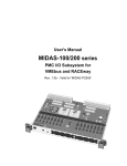
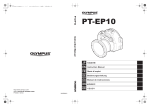
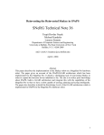
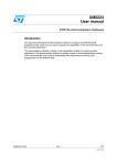
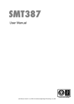
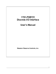
User's Manual MIDAS-20/20R MIDAS-50/50R PMC Carriers for VMEbus and RACEway Valid for MIDAS-20 PCB-C Rev. 1.7 Front Panel I/O Front Panel I/O PCI Mezzanine Card PCI Mezzanine Card PCI Mezzanine Card (PMC#1) (PMC#2) (PMC#3) pPCI PCI-to-PCI PCI Mezzanine Card PCI Mezzanine Card (PMC#4) (PMC#5) sPCI sPCI * PCI-toRACEway (Optional) P2a&c VME64 Master Slave/DMA P2a&c P2z&d P2 I/O VMEbus P2z&d P2 I/O MIDAS-20* MIDAS-50 The information in this document is subject to change without notice and should not be construed as a commitment by VMETRO. While reasonable precautions have been taken, VMETRO assumes no responsibility for any errors that may appear in this document. © Copyright VMETRO 2000. This document may not be furnished or disclosed to any third party and may not be copied or reproduced in any form , electronic, mechanical, or otherwise, in whole or in part, without prior written consent of VMETRO Inc. (Houston, TX, USA) or VMETRO ASA (Oslo, Norway). ii MIDAS-20/20R & MIDAS-50/50R USER's GUIDE Warranty VMETRO products are warranted against defective materials and workmanship within the warranty period of 1 (one) year from date of invoice. Within the warranty period, VMETRO will, free of charge, repair or replace any defective unit covered by this warranty, shipping prepaid. A Return Authorization Code should be obtained from VMETRO prior to return of any defective product. With any returned product, a written description of the nature of malfunction should be enclosed. The product must be shipped in its original shipping container or similar packaging with sufficient mechanical and electrical protection in order to maintain warranty. This warranty assumes normal use. Products subjected to unreasonably rough handling, negligence, abnormal voltages, abrasion, unauthorized parts replacement and repairs, or theft are not covered by this warranty and will if possible be repaired for time and material charges in effect at the time of repair. Any customer modification to VMETRO products, including conformal coating, voids the warranty unless agreed to in writing by VMETRO. If boards that have been modified are returned for repair, this modification should be removed prior to the board being shipped back to VMETRO for the best possibility of repair. Boards received without the modification removed will be reviewed for repairability. If it is determined that the board is not repairable, the board will returned to the customer. All review and repair time will be billed to the customer at the current time and materials rates for repair actions. VMETRO's warranty is limited to the repair or replacement policy described above and neither VMETRO nor its agent shall be responsible for consequential or special damages related to the use of their products. Limited Liability VMETRO does not assume any liability arising out of the application or use of any product described herein; neither does it convey any license under its patent rights nor the rights of others. VMETRO products are not designed, intended, or authorized for use as components in systems intended to support or sustain life, or for any application in which failure of the VMETRO product could create a situation where personal injury or death may occur. Should Buyer purchase or use VMETRO products for any such unintended or unauthorized application, Buyer shall indemnify and hold VMETRO and its officers, employees, subsidiaries, affiliates, and distributors harmless against all claims, costs, damages, and expenses, and reasonable attorney fees arising out of, directly or indirectly, any claim of personal injury or death associated with such unintended or unauthorized use, even if such claim alleges that VMETRO was negligent regarding the design or manufacture of the part. USA: VMETRO, Inc. 1880 Dairy Ashford, Suite 535 Houston, TX 77077, USA Tel.: (281) 584-0728 Fax: (281) 584-9034 Email: [email protected] Europe, Asia: VMETRO asa Brynsveien 5 N-0667 OSLO, Norway Tel.: +47 2210 6090 Fax: +47 2210 6202 Email: [email protected] http://www.vmetro.com/ MIDAS-20/20R & MIDAS-50/50R USER's GUIDE iii Contents General Information 1 This document ...........................................................................................................................1 Conventions used in this document ...........................................................................................1 Related Documents....................................................................................................................2 Product Overview 3 MIDAS-20/20R .........................................................................................................................4 MIDAS-50/50R .........................................................................................................................5 Installation 6 Board Precautions .....................................................................................................................6 Unpacking .................................................................................................................................6 Installation of PMC Modules ....................................................................................................6 Assembly Procedure for MIDAS-50/50R..................................................................................6 Installation in VMEbus System ...............................................................................................10 Slot selection .............................................................................................................10 MIDAS-50 Daisy-Chain............................................................................................10 Power consumption .................................................................................................................10 PMC current supply capabilities ...............................................................................10 Configuration Switch & Jumpers.............................................................................................11 Auto-Slot ID..............................................................................................................11 VMEbus Switch & Jumper Descriptions...................................................................11 RACEway Interface Jumper Descriptions.................................................................14 Functional Description 16 PCI Bus 'IDSEL' Generation ...................................................................................................16 Interrupt Routing .....................................................................................................................16 Subtractive Decoding Agent....................................................................................................17 'Universe' Power-Up Options ..................................................................................................17 Registers ..................................................................................................................................18 Register Access from VMEbus .................................................................................18 Register Access from PCI Bus ..................................................................................19 Register Descriptions ................................................................................................19 Configuration ROM ..................................................................................................20 Appendix I: MIDAS-20/50 PMC I/O Routing 21 Appendix II: MIDAS-20Z PMC I/O Routing 22 Appendix III: Universe Configuration Examples 23 General Information ................................................................................................................23 VMEbus Slave Images ............................................................................................................23 PCI Master Enable ....................................................................................................23 VMEbus Register Access Image ...............................................................................24 VMEbus Slave Image 0.............................................................................................25 VMEbus Slave Image 1.............................................................................................25 VMEbus Slave Image 2.............................................................................................26 iv MIDAS-20/20R & MIDAS-50/50R USER's GUIDE Initialization Sequence ..............................................................................................27 PCI Slave Images ....................................................................................................................27 PCI Target Enable - Memory & I/O Space ...............................................................27 PCI Slave Image 0.....................................................................................................28 PCI Slave Image 1.....................................................................................................29 PCI Slave Image 2.....................................................................................................29 Initialization Sequence ..............................................................................................30 Appendix IV: INTEL 21152 Configuration Example 31 Universe Initialization Sequence...............................................................................31 Intel 21152 Configuration Sequence.........................................................................32 Scan PCI Config. Space on MIDAS-50/50R ...........................................................33 Appendix V: PXB Information 34 PXB PCI-RACEway Bridge....................................................................................................34 PXB Register Descriptions......................................................................................................35 P-Side Register Descriptions.....................................................................................35 X-Side Register Descriptions ....................................................................................44 Miscellaneous PXB Information .............................................................................................45 Configuration Serial EEPROM .................................................................................45 PCI-to-RACEway Addressing...................................................................................45 RACEway-to-PCI Addressing...................................................................................47 PCI-to-PCI Bridge Operation....................................................................................47 PXB Initialization Example.....................................................................................................48 MIDAS-20/20R & MIDAS-50/50R USER's GUIDE v General Information This document This document has been prepared to help the customer in the integration of the products MIDAS-20/20R and MIDAS-50/50R in their system. The following models are covered by this document: MIDAS-20: Dual PMC Carrier for VMEbus. MIDAS-20Z: Dual PMC Carrier for VMEbus, with 5 row DIN connectors MIDAS-20R: Dual PMC Carrier for VMEbus, with an interface to the RACEway crossbar interconnect. MIDAS-50: PMC Carrier for VMEbus, capable of carrying up to 5 PMC modules. MIDAS-50R: PMC Carrier for VMEbus, capable of carrying up to 5 PMC modules, with an interface to the RACEway crossbar interconnect. During this document, the generic name “MIDAS” refers to all models whenever their common features are described. Conventions used in this document The following section describes conventions used in this document. Symbols Meaning: The STOP symbol indicates a section of critical importance. Overlooking this information may cause damage to the MIDAS and/or other equipment. Indicates important, but not crucial information. Still, you should take notice if you want to use all capabilities built into your MIDAS. MIDAS-20/20R & MIDAS-50/50R USER's GUIDE 1 Related Documents This document does not include detailed information about the 'Universe II', VME-to-PCI bridge chip, the 21152 PCI-to-PCI bridge and the PCI-to-RACEway interface chip; the PXB. A majority of the control registers and a large part of the complexity of the products is implemented in these chips. The documents related to these chips contain essential information for understanding the products. The following documents can be provided directly from the chip vendor (also available on the internet): Tundra Semiconductor Corp.: UNIVERSE II USER MANUAL http://www.tundra.com/ INTEL: 21152 PCI TO PCI BRIDGE http://www.intel.com/design/bridge/datasheets/ Information should also include updated information on device errata. A copy of the documents listed above along with the PXB BRIDGE SPECIFICATION can be obtained directly from VMETRO1. 1 2 MIDAS Doc. Kit. MIDAS-20/20R & MIDAS-50/50R USER's GUIDE Product Overview VMEbus Configuration Jumpers JTAG Connector Reset Button MIDAS-20 PCB-C PCI CONNECTORS for MIDAS-50/50R Expansion PCI CONNECTORS - PMC#2 P2 I/O CONNECTOR - PMC#2 (Not mounted for -R option) Universe VME-to-PCI PCI CONNECTORS - PMC#1 P2 I/O CONNECTOR - PMC#1 (Not mounted for -R option) PXB RACEway-PCI Bridge RACEway-PCI SERIAL NO: RACEway Jumpers Figure 1. MIDAS-20R board layout. Expantion connectors and the PCI-to-PCI bridge are mounted only on the MIDAS-50/50R mother board. MIDAS-20/20R & MIDAS-50/50R USER's GUIDE 3 MIDAS-20 PCB-C SPACER-x50 MEZZ-x50 PCB-A J50 SPACER-x50 J51 J52 J51 J52 J21 J22 DECchip 21052 J41 J42 J24 J44 J11 J31 J12 J32 J14 SERIAL NO: J34 MIDAS-50 mother board MEZZ-x50 Figure 2. MIDAS-50: MEZZ-x50 + SPACER-x50 + MIDAS-50 mother board MIDAS-20/20R PMC#1 VMEbus 'Universe' PMC#2 PCI bus CROM PXB RACEway Figure 3. MIDAS-20R Block Diagram The MIDAS-20 is a PMC carrier for VMEbus . The MIDAS-20R option, contains the PCI-to-RACEway interface chip; the PXB. The MIDAS-20/20R with the PCI-to-PCI bridge and the expantion connectors mounted on it provides the mother board for the MIDAS-50/50R. 4 MIDAS-20/20R & MIDAS-50/50R USER's GUIDE MIDAS-50/50R MIDAS-50R mother board PMC#1 VMEbus 'Universe-II' PMC#2 PMC#3 Intel 21052 PCI bus (primary) CROM MEZZ-x50 PCI-PCI PMC#4 PMC#5 PCI bus (secondary) PXB RACEway Figure 4. MIDAS-50R Block Diagram The MIDAS-50 is a PMC carrier VMEbus board which supports up to five PMC slots. The MIDAS-50R option, contains the PCI-to-RACEway interface chip; the PXB. The MIDAS-50 occupies two VMEbus slots. MIDAS-20/20R & MIDAS-50/50R USER's GUIDE 5 Installation Board Precautions The circuit boards are sensitive to static electricity and can be damaged by a static discharge. Always wear a grounded anti-static wrist strap and use grounded, static protected work surfaces when touching the circuit boards and their components. When the board is not installed, always keep it in its static-protective envelope. Unpacking All precautions described above must be taken when unpacking the product from its shipping container(s). Verify that no damage has occurred in the shipment. Verify that all items are present: MIDAS-20/20R: • One MIDAS-20/20R board. • This manual. MIDAS-50/50R: • One dual slot VMEbus plug-in unit consisting of: - One MIDAS-50/50R mother board. - One MEZZ-x50 board. - One SPACER-x50 board. - Five metal spacers. • This manual. Installation of PMC Modules The MIDAS-20/20R and MIDAS-50/50R are shipped with PMC filler panels mounted in the front panel. They act as EMC shielding in unused PMC positions. Before installing a PMC module the filler panel(s) must be removed. This is done by pushing them out from the back side of the front panel. Please refer to assembly procedures below for further instructions on the installation of PMC modules. Assembly Procedure for MIDAS-50/50R The MIDAS-50/50R is a dual slot VMEbus board which mates the backplane connectors in two neighbor slots. The MIDAS-50/50R module can handle the insertion and extraction forces applied when installing or removing it from the backplane. However, this requires that the assembly procedure described in this section is followed. WARNING: The MIDAS-50/50R boards may be destroyed during insertion or extraction from a VMEbus system if this procedure is not followed. 6 MIDAS-20/20R & MIDAS-50/50R USER's GUIDE STEP#1: Dismount MEZZ-x50 board from MIDAS-50/50R board. - Place the MIDAS-50/50R board on a smooth static protected work surface with the bottom side of the board facing up. - From the bottom side of the MIDAS-50/50R PCB, unscrew the 5 screws holding the metal spacers between the MEZZ-x50 and the mother board. (these screws are located close to the edge of the board in each corner, and between the VMEbus connectors). Note: Don't throw away the screws. They are needed later in this procedure. - Pull the boards carefully apart. Use hand force only, applied to the two the upper VMEbus connector of both boards. - If the small SPACER-x50 PCB is attached to the MIDAS-50/50R mother board PCB after the separation, remove it and mount it on the bottom side of the MEZZ-x50 board instead. STEP#2: Mount PMC modules 1 and 2 on the MIDAS-50/50R mother board. - Place the MIDAS-50/50R mother board on a smooth static protected work surface. - Install PMC module #1 in the lower PMC position - Install PMC module #2 in the upper PMC position - Secure PMC modules with screws from the bottom side of the mother board. STEP#3: Mount PMC modules 3, 4 and 5 on the MEZZ-x50 board. - Place the MEZZ-x50 board on a smooth static protected work surface. - Install PMC module #3 in the lower PMC position - Install PMC module #4 in the middle PMC position - Install PMC module #5 in the upper PMC position - Secure PMC modules with screws from the bottom side of the MEZZ-x50 board. MIDAS-20/20R & MIDAS-50/50R USER's GUIDE 7 MEZZ-x50 PCB-A MIDAS-20 PCB-C J51 J52 J50 PMC MODULE #5 J51 J52 J21 J22 DECchip 21052 J41 J42 PMC MODULE #2 PMC MODULE #4 J24 J44 J31 J11 J32 J12 PMC MODULE #1 PMC MODULE #3 J14 J34 MIDAS-20 PMC Carrier for VMEbus Figure 5. Steps 2&3: Mount PMC modules on the MEZZ-x50 and the MIDAS-50 mother board. Note: Before proceeding, make sure that the switch and jumper settings on the MIDAS-50/50R mother board is according to the needs of your application. STEP#4: Mount MEZZ-x50 with PMC modules on the MIDAS-50/50R mother board. - If the SPACER-x50 board and the five metal spacers are not already mounted on the bottom side of the MEZZ-x50 board, do it now. - Place the MIDAS-50/50R mother board on a smooth static protected work surface. - Carefully position the MEZZ-x50 board over the MIDAS-50/50R mother board, so that the three connector on the bottom side of the spacer are aligned with the connectors J50, J51 and J52 on the MIDAS-50/50R mother board. Make sure that neither of the five metal spacers mounted on the MEZZ-x50 board touches components or component leads on the MIDAS-50/50R mother board in the process. - Push the MEZZ-x50 board down so that all connectors mate completely. 8 MIDAS-20/20R & MIDAS-50/50R USER's GUIDE MIDAS-20 PCB-C J50 MEZZ-x50 PCB-A J51 PMCMODULE#5 J52 J51 J52 PMCMODULE#2 DECchip21052 J21 J22 PMCMODULE#4 J24 J41 J42 PMCMODULE#1 J44 PMCMODULE#3 J11 J12 J14 J31 J32 MIDAS-20 J34 Figure 6. Step 4: Mount the MEZZ-x50 with PMC modules on the MIDAS-50/50R mother board. STEP#5: Mount and fasten screws to all metal spacers from the back of the MIDAS50/50R mother board. - Take the 5 screws removed in step#1 of this procedure, and mount them from the back side of the MIDAS-50/50R mother board through the holes which mate the 5 metal spacers on the MEZZ-x50. - Fasten all five screws with a suitable screw driver. - Verify that the screws attaching the metal spacers to the MEZZ-x50 are also fastened. - All screws holding the five metal spacers from both boards must be firmly fastened in order to make the MIDAS-50/50R mechanically stable. MIDAS-20/20R & MIDAS-50/50R USER's GUIDE 9 Installation in VMEbus System Slot selection The MIDAS can be installed in any slot in a 6U VMEbus chassis as long as the daisychains for the bus grant and interrupt acknowledge signals are continuous from slot#1 to the slot in which the board is installed. If the MIDAS is installed in slot#1 of a VMEbus system it will automatically detect this as specified in the VME64 specification and enable its system controller functions. WARNING: Do not install the board in a powered system! MIDAS-50 Daisy-Chain The P1 connector of the MEZZ-x50 provides a daisy-chain bypass for the signals BG[3:0]* and IACKIO*. No action is therefor required to keep the daisy-chain continuous through the MIDAS-50/50R board. Power consumption Model Typical current consumption (5V) Test condition 1) 0.5A Board idle 1.0A Board active 1A Board idle M20 1) M20R 1.8A Board active Table 1: Power consumption PMC current supply capabilities The MIDAS M20x has the ability to power both 5 and 3.3 Volt PMC modules with the following limitations. Voltage Maximum current Additional information 2) 1) Max. total current 3.3 5 4A Supplied from VME Refer to PMC standard. backplane. Table 2: Current supply Capabilities 1) Note: as 3.3V is supplied by a linear regulator mounted on the MIDAS, additional current drawn from 3.3V has a direct effect on the 5 Volt power consumed. 2) 10 3.3 Volt capabilities available on MIDAS 20 with ECO level C.3 or higher. MIDAS-20/20R & MIDAS-50/50R USER's GUIDE Configuration Switch & Jumpers The VME-PCI bridge on the MIDAS-20/20R and MIDAS-50/50R boards has a number of configuration registers which need to be initialized before the bridge is fully operational. This initialization is done by a host processor residing either on VMEbus or on the local PCI bus. This host is normally on VMEbus. The switch and jumpers cannot alone be used to initialize the MIDAS board. They are used to define how (base address, address space etc. for initialization) the initialization is done. Note: When the Auto-Slot ID feature is enabled, the MIDAS board asserts IRQ2* on VMEbus reset. Auto-Slot ID Plug&Play The MIDAS has full support for the Auto-Slot ID mechanism as defined by the VME64 specification. By use of the daisy-chained IACK signal, CR/CSR space accesses are enabled for one VME slot at a time. Thus, the "Monarch" (host for initialization) is able to recognize installed modules and initialize them to achieve Plug&Play VMEbus systems. The board is shipped with a jumper setting in which Auto-Slot ID is enabled. This means that MIDAS can be plugged directly into PnP VMEbus systems without moving jumpers. VMEbus Switch & Jumper Descriptions VRAI MIDAS has one DIP switch and five jumpers used for VMEbus configuration. S FAIL AUTO ID 1 2 3 4 5 6 7 8 Figure 7. MIDAS Configuration Switch and Jumpers (Auto-Slot ID settings shown) Switch & Jumpers for "manual" configuration. The DIP-Switch and three of the jumpers are of this category. Unless the Auto-Slot ID protocol is used by the host system (see section above, and descriptions below) these switch/jumpers should be used to define a window in the VMEbus address space for configuration of the VME-PCI bridge on MIDAS. VME Register Access Image - ENABLE/DISABLE The VME Register Access Image (VRAI) permits accesses from VMEbus to the VME-PCI bridge internal registers at power-up. Unless the Auto-Slot ID protocol (which uses its MIDAS-20/20R & MIDAS-50/50R USER's GUIDE 11 VRAI own slave image) is used, this slave image must be enabled to allow initialization from VMEbus. 2 3 4 5 6 7 8 DOWN: VRAI UP: 2 3 4 5 6 VME Register Access Image ENABLED. 7 8 S FAIL 1 AUTO ID VME Register Access Image DISABLED. S FAIL AUTO ID 1 VME Register Access Image (address size) UP/UP: 2 3 4 5 6 7 8 1 2 3 4 5 6 7 8 DOWN/DOWN: 1 2 3 4 5 6 7 8 UP/DOWN: VME Register Access Image A24. S FAIL 1 S FAIL VME Register Access Image A32. S FAIL AUTO ID VRAI AUTO ID VRAI AUTO ID VRAI The VME Register Access Image can accept A16, A24 or A32 AM codes depending on the positioning of these two jumpers. At power-up this slave image accepts AM codes for: Supervisor, User, Data and Code. VME Register Access Image A16. VME Register Access Base Address The DIP switch is used to define the base address for the VME Register Access Image. The size of this image is fixed to 4KB. 12 MIDAS-20/20R & MIDAS-50/50R USER's GUIDE BASE ADDRESS VRAI Addr. Size BS[31:24] BS[23:16] BS[15:12] A16 N.A. N.A. From switch (4 MSB) A24 N.A. From switch 0x00 A32 From switch 0x00 0x00 Table 3. VRAI Base Address Definition not used for A16 Most Significant Bit (MSB) 1 2 3 4 5 6 7 8 Figure 8. DIP Switch Details. VME64 Auto-Slot ID - ENABLE/DISABLE By the use of a new address space for CR/CSR accesses, the VME64 specification defines a method for implementing Plug&Play on VMEbus called Auto-Slot ID. The AUTO ID jumper controls the enabling of the VME64 Auto-Slot ID mechanism. Note that to fully support Auto-Slot ID the "Monarch" needs access to Configuration ROM data located on the PCI bus. 2 3 4 5 6 7 8 1 2 3 4 5 6 7 8 UP: VME64 AUTO-SLOT ID ENABLED. DOWN: VME64 AUTO-SLOT ID DISABLED. S FAIL 1 S FAIL AUTO ID VRAI AUTO ID VRAI Note: When the Auto-Slot ID feature is enabled, the MIDAS board asserts IRQ2* on VMEbus reset. MIDAS-20/20R & MIDAS-50/50R USER's GUIDE 13 SYSFAIL* Assertion 2 3 4 5 6 7 8 1 2 3 4 5 6 7 8 UP: SYSFAIL ASSERTION DISABLED. DOWN: SYSFAIL ASSERTION ENABLED. S FAIL 1 S FAIL AUTO ID VRAI AUTO ID VRAI This jumper can be used to make the Universe assert SYSFAIL* upon reset/power-up. Normally this option should be disabled (Jumper in its upper position). RACEway Interface Jumper Descriptions The MIDAS-20R/50R models incorporate the PXB chip, a PCI-RACEway bridge developed by Mercury Computer Systems2. MIDAS has two jumpers for configuration of the RACEway interface. They are located close to the bottom edge of the board, indicated with silk-screen text: RACEWAY. As explained in the description below, both RACEway jumpers are removed during normal operation. No EEPROM When the No EEPROM jumper (leftmost RACEway jumper) is removed, the PCIRACEway bridge chip loads its internal registers from a serial EEPROM. This setting should always be used, except for cases where the PROM is blank or corrupted. If the PROM is corrupted, and this jumper is removed, the PCI-RACEway bridge may reset to a state which causes the MIDAS board (in worst case the entire system) to hang. RACEway RACEway If the No EEPROM jumper is inserted, the PCI-RACEway bridge reset state is independent of the PROM contents. This setting is normally used for the initial programming of the PROM or if the board is plugged into a non-RACEway slot. Note that before programming the PROM, the PXB must be set in bridge mode. 2 Inserted: PXB registers not loaded from EEPROM. Removed: PXB registers loaded from EEPROM. For more information about this chip and some configuration examples, please refer to Appendix IV. 14 MIDAS-20/20R & MIDAS-50/50R USER's GUIDE Reset from X When the Reset from X jumper (rightmost RACEway jumper) is removed, the PCIRACEway bridge receives reset from PCI bus (i.e. MIDAS reset circuitry), and drives reset to the RACEway interlink. This setting should always be used. RACEway Inserting this jumper may be destructive for the MIDAS board, and is likely to cause system malfunction. Removed: MIDAS-20/20R & MIDAS-50/50R USER's GUIDE This setting should always be used. 15 Functional Description PCI Bus 'IDSEL' Generation PCI bus uses a separate address space for initialization called Configuration Space. This address space uses a geographic addressing signal; IDSEL to select target for all transactions. The standard way of assigning IDSEL to PCI devices & boards is to connect the IDSEL pin of each device/board to a unique AD[ ] bit. This is also how IDSEL is generated on MIDAS. The table below shows IDSEL assignments. PCI DEVICE/BOARD IDSEL PCI ADDRESS FOR CONFIG. CYCLE VME BASE ADDRESS FOR PCI CONFIG. CYCLE PMC # 1 AD[16] 0x00010XXX 0xYYZZ2800 PMC # 2 AD[17] 0x00020XXX 0xYYZZ3000 AD[20] 0x00100XXX 0xYYZZ4800 PXB PCI-RACEway AD[19] 0x00080XXX 0xYYZZ4000 VME-PCI BRIDGE AD[31] 0x80000XXX PCI-to-PCI Bridge 3 4 'ZZ' = PCI Bus Number (as defined in Universe MAST_CTL register) 'YY' = VME base address for slave image Table 4. IDSEL Assignments for Primary PCI Bus PCI DEVICE/BOARD IDSEL PCI ADDRESS FOR CONFIG. CYCLE VME BASE ADDRESS FOR PCI CONFIG. CYCLE PMC # 3 sAD[16] 0x00010XXX 0xYYWW0000 PMC # 4 sAD[17] 0x00020XXX 0xYYWW0800 PMC # 5 sAD[18] 0x00040XXX 0xYYWW1000 'WW' = PCI Bus Number for secondary bus (as defined in the PCI-to-PCI bridge) 'YY' = VME base address for slave image Table 5. IDSEL Assignments for Secondary PCI Bus on MIDAS-50/50R Interrupt Routing The VME-PCI bridge provides eight bi-directional interrupt pins to the local bus interface. Their routing to PMC interrupt pins is shown in the tables below: 3 4 The P2P bridge is only present on the MIDAS-50/50R mother board. The PXB chip is only present on the MIDAS-20R/50R model. 16 MIDAS-20/20R & MIDAS-50/50R USER's GUIDE For details on setting up interrupt channels, please refer to the UNIVERSE II USER MANUAL. UNIVERSE INT. PMC # 1 LINT#[0] PMC # 2 PMC # 3 PMC # 4 PMC # 5 INTA# INTC# INTB# INTB# INTD# INTC# INTC# INTA# INTD# INTD# INTB# INTA# INTA# LINT#[1] INTA# LINT#[2] INTB# LINT#[3] INTB# LINT#[4] INTC# LINT#[5] INTC# LINT#[6] INTD# LINT#[7] INTD# Table 6. MIDAS-20/50 Interrupt Routing UNIVERSE INT. PXB PMC # 1 PMC # 2 PMC # 3 PMC # 4 PMC # 5 LINT#[4] INTA# INTB# INTC# INTA# INTC# INTB# LINT#[5] INTB# INTC# INTA# INTB# INTD# INTC# LINT#[6] INTC# INTA# INTD# INTC# INTA# INTD# LINT#[7] INTD# INTD# INTB# INTD# INTB# INTA# LINT#[0] LINT#[1] LINT#[2] LINT#[3] Table 7. MIDAS-20R/50R Interrupt Routing Subtractive Decoding Agent The CR/CSR PLD utilizes subtractive decoding in the PCI bus I/O Space. No other PCI devices are therefor allowed to do the same. Subtractive decoding in Memory Space may be used. 'Universe' Power-Up Options A number of power-up options are loaded by the 'Universe' after power-up or system reset. A detailed description of these options is found in the UNIVERSE™ USER MANUAL. The table below shows how they are controlled on the MIDAS. MIDAS-20/20R & MIDAS-50/50R USER's GUIDE 17 Option: Field MIDAS-20 EN VRAI jumper VAS address size jumpers BS Switch LAS I/O Space VCSR_TO TO '0x00' PCI_CSR MAST_EN Enabled EN Disabled LAS Mem. space VAS A16 LSI0_BS BS 0x0 LSI0 BD 0x0 SPACE I/O Space Enabled Register by VME Register Access Slave Image PWR/SYS VRAI_CTL VRAI_BS VME CR/CSR Slave Image PCI Slave Image PWR/SYS VCSR_CTL PWR/SYS LSI0_CTL PCI Register Access PWR/SYS PCI_BS PCI Bus Size RST# Auto-ID MISC_STAT LCLSIZE PWR/SYS MISC_STAT DY4AUTO 32-bit Disabled VME64AUTO AUTO ID jumper BI-Mode PWR/SYS MISC_CTL BI Disabled SYSFAIL* Assertion PWR/SYS VCSR_SET SYSFAIL S FAIL jumper VCSR_CLR SYSFAIL MISC_CTL SYSCON Auto-Syscon Detect SYS Enabled Table 8. 'Universe' Power-Up Options Registers The VME-PCI bridge on MIDAS is highly programmable through a large number of internal registers. In addition to this, MIDAS has one status register and a configuration ROM implemented in a PLD. All register & ROM locations on MIDAS can be accessed from VMEbus as well as from the PMC modules. Note that parity is not generated when reading the MIDAS status register and configuration ROM. Parity errors should therefor be disregarded when reading these locations. In the power-up state of the Universe VME-PCI bridge, parity errors are disregarded. Register Access from VMEbus The MIDAS CR/CSR PLD is accessed using PCI bus I/O Space commands. From VMEbus this is done by accessing the CR/CSR address space of the board, or by using one of the four VMEbus Slave Images in the VME-PCI bridge. This image must be set up to generate I/O Space accesses on PCI bus. 18 MIDAS-20/20R & MIDAS-50/50R USER's GUIDE Please refer to UNIVERSE™ USER MANUAL for details, and for information on how to access registers internal to the VME-PCI bridge. Register Access from PCI Bus The MIDAS CR/CSR PLD can be accessed directly from the PMC modules or the RACEway (through the PXB chip) by the use of the PCI bus I/O Space commands. Register Descriptions 'Universe' Registers Please refer to UNIVERSE™ USER MANUAL for this information. 'PXB' Registers Please refer to PXB BRIDGE SPECIFICATION and Appendix IV for this information. MIDAS-20/20R & MIDAS-50/50R USER's GUIDE 19 Configuration ROM MIDAS Configuration ROM CROM Offset Offset: 03 (VME CR/CSR Space) ROM Value 03 Description Checksum. Eight bit 2s complement binary checksum (CR bytes 03-7F). 07 00 Length of ROM to be checksummed. (MSB) 0B 00 Length of ROM to be checksummed. (NMSB) 0F 1F Length of ROM to be checksummed. (LSB) 13 81 CR Data access width (0x81 = D08(EO), every forth byte) 17 81 CSR Data access width (0x81 = D08(EO), every forth byte) 1B 01 CR/CSR Space Specification ID (0x01 = VME64 - 1994 version) 1F 43 'C'. Used to identify valid CR. 23 52 'R'. Used to identify valid CR. 27 00 24 bit IEEE Assigned Manufacturers ID. 2B 60 0x006046 = VMETRO 2F 46 33 00 Board ID (VMETRO Assigned) 37 10 0x00100020 = MIDAS-20 3B 00 3F 20 43 00 Revision ID (VMETRO Assigned) 47 00 Example 0x0000C001 = PCB Rev: C, ECO-level:1 4B PCB-rev. 4F ECO-level 53 00 Pointer to null terminated ASCII string. Revision ID (VMETRO Assigned) 57 00 0x000000 = No string 5B 00 5F-7B 00 Reserved for future use 7F 01 Program ID Code. 0x01 = No program, ID ROM only. Table 9. MIDAS-20/20R and MIDAS-50/50R Configuration ROM 20 MIDAS-20/20R & MIDAS-50/50R USER's GUIDE Appendix I: MIDAS-20/50 PMC I/O Routing The I/O connectors for PMC slots on the MIDAS-20R and the mother board of the MIDAS-50R are not mounted, and P2 rows A and C are used for the RACEway. PMC2&4 J4 PMC1&3 J4 P2 row A P2 row C PMC1&3 J4 PMC2&4 J4 34 2 1 1 1 33 36 4 2 2 3 35 38 6 3 3 5 37 40 8 4 4 7 39 42 10 5 5 9 41 44 12 6 6 11 43 46 14 7 7 13 45 48 16 8 8 15 47 50 18 9 9 17 49 52 20 10 10 19 51 54 22 11 11 21 53 56 24 12 12 23 55 58 26 13 13 25 57 60 28 14 14 27 59 62 30 15 15 29 61 64 32 16 16 31 63 34 17 17 33 36 18 18 35 38 19 19 37 40 20 20 39 42 21 21 41 44 22 22 43 46 23 23 45 48 24 24 47 50 25 25 49 52 26 26 51 54 27 27 53 56 28 28 55 58 29 29 57 60 30 30 59 62 31 31 61 64 32 32 63 MIDAS-20/20R & MIDAS-50/50R USER's GUIDE 21 Appendix II: MIDAS-20Z PMC I/O Routing PMC1 J4 P2 A P2 C PMC1 J4 PMC2 J4 P2 Z P2 D PMC2 J4 2 1 1 1 2 1 1 1 4 2 2 3 2 2 3 6 3 3 5 3 3 4 8 4 4 7 4 4 6 10 5 5 9 5 5 7 12 6 6 11 6 6 9 14 7 7 13 7 7 10 16 8 8 15 8 8 12 18 9 9 17 9 9 13 20 10 10 19 10 10 15 22 11 11 21 11 11 16 24 12 12 23 12 12 18 26 13 13 25 13 13 19 28 14 14 27 14 14 21 30 15 15 29 15 15 22 32 16 16 31 16 16 24 34 17 17 33 17 17 25 36 18 18 35 18 18 27 38 19 19 37 19 19 28 40 20 20 39 20 20 30 42 21 21 41 21 21 31 44 22 22 43 22 22 33 46 23 23 45 23 23 34 48 24 24 47 24 24 36 50 25 25 49 25 25 37 52 26 26 51 26 26 39 54 27 27 53 27 27 40 56 28 28 55 28 28 42 58 29 29 57 29 29 43 60 30 30 59 30 30 45 62 31 31 61 31 31 64 32 32 63 32 32 22 5 8 11 14 17 20 23 26 29 32 35 38 41 44 46 MIDAS-20/20R & MIDAS-50/50R USER's GUIDE Appendix III: Universe Configuration Examples General Information Note that the 'Universe' PCI-VME Bridge, performs byte swapping of the data lanes on all transactions between VMEbus and PCI bus. This is also the case for accesses to the internal registers. The internal register bank is located on the 'PCI side' of the byte swapping. This means that when registers are read or written from the VMEbus, all bytes are shuffled (compared to the bit numbering used in the Universe User Manual). VMEbus Slave Images PCI Master Enable In addition to the configuration registers for the VMEbus slave images, one control register bit is essential for mapping VMEbus cycles to PCI bus cycles through the Universe; the PCI master enable ('BM') bit located in the PCI_CSR register space (offset: 0x004). This bit is set as a default after power up. Some VMEbus Slave Image examples are shown bellow: MIDAS-20/20R & MIDAS-50/50R USER's GUIDE 23 VMEbus PCI bus UNIVERSE 0x000000 VMEbus A24, all AM codes VME Register Access Image 0x000FFF 0x0000 VMEbus A16, supervisor AM codes VME Slave Image #0 PCI bus Config. Space 0x4FFF 0x02100000 0x100000 VMEbus A24, all AM codes, No write-posting or read prefetching. PCI Lock of VMEbus RMW enabled. VME Slave Image #1 PCI bus I/O Space. 0x3FFFFF 0x023FFFFF 0x4000.0000 0x6000.0000 VMEbus A32, all AM codes, Write-posting and read prefetching enabled. VME Slave Image #2 PCI bus Memory Space. 0x9FFF.FFFF 0x7FFF.FFFF VME Slave Image # 3 (not used) Figure 9. Configuration Example for VMEbus Slave Images VMEbus Register Access Image In this configuration example, the VMEbus Register Access Image is set up by use of the DIP switch and jumpers. 24 MIDAS-20/20R & MIDAS-50/50R USER's GUIDE Action: Result: Locate VRAI in its upper position. VME_RAI is enabled. Locate both of the address size jumpers in their upper positions. VME_RAI is mapped in A24 address space. Set the DIP switch with all switches pointing down. VME_RAI base address is set to 0x000000. Locate the Auto ID jumper in its lower position. Disable Auto-slot ID protocol. Table 10. VME_RAI Setup. With the jumper settings described above, the Universe will power up in a state where VMEbus accesses with A24 AM codes, in the address range 0x0-0xFFF, will map into Universe registers. The VME_RAI will be utilized to set up the VMEbus slave images described below. VMEbus Slave Image 0 In this configuration example, the VMEbus Slave Image 0 is set up to map A16 supervisory accesses, in the address range 0x0-0x4FFF, from VMEbus to Configuration Cycles on the PCI bus. Write from VME PCI Data 1) Result: D:0x0000.0000 to A:0x000F04 0x0000.0000 Base Address set to 0x000000 D:0x0050.0000 to A:0x000F08 0x0000.5000 Bound Address set to 0x005000 D:0x0000.0000 to A:0x000F0C 0x0000.0000 Translation Offset set to 0x000000 D:0x0200.E080 to A:0x000F00 0x80E0.0002 Enable Image, VAS=A16, LAS=Config Space, PGM=both, SUPER=Supervisor, other options disabled. 1) This column shows write data for configuration from PCI Table 11. VME Slave Image 0 - Setup VMEbus Slave Image 1 The VMEbus Slave Image 1 is set up to map A24 accesses, in the address range 0x100000-0x3FFFFF from VMEbus to I/O Cycles on the PCI bus, with PCI addresses starting from 0x02100000. MIDAS-20/20R & MIDAS-50/50R USER's GUIDE 25 Write from VME PCI Data 1) Result: D:0x0000.1000 to A:0x000F18 0x0010.0000 Base Address set to 0x100000 D:0x0000.4000 to A:0x000F1C 0x0040.0000 Bound Address set to 0x400000 D:0x0000.0002 to A:0x000F20 0x0200.0000 Translation Offset set to 0x2000000 D:0x4100.F180 to A:0x000F14 0x80F1.0041 Enable Image, VAS=A24, LAS=I/O Space, PGM=both, SUPER=both, LLRMW=enabled, other options disabled. Table 12. VME Slave Image 1 - Setup. 1) This column shows write data for configuration from PCI VMEbus Slave Image 2 VMEbus Slave Image 2 is set up to map A32 accesses, in the address range 0x4000.0000-0x7FFF.FFFF, from VMEbus to Memory Cycles on the PCI bus, with PCI addresses starting from 0x6000.0000. Write posting and read prefetching is enabled. Write from VME PCI Data 1) Result: D:0x0000.0040 to A:0x000F2C 0x4000.0000 Base Address set to 0x4000.0000 D:0x0000.0080 to A:0x000F30 0x8000.0000 Bound Address set to 0x8000.0000 D:0x0000.0020 to A:0x000F34 0x2000.0000 Translation Offset set to 0x2000.0000 D:0x0000.F2E0 to A:0x000F28 0xE0F2.0000 Enable Image, VAS=A32, LAS=Mem. Space, PGM=both, SUPER=both, PWEN&PREN= enabled, other options disabled. 1) This column shows write data for configuration from PCI Table 13. VME Slave Image 2 - Setup. 26 MIDAS-20/20R & MIDAS-50/50R USER's GUIDE Initialization Sequence By performing the list of cycles shown in the table below, the mapping for this configuration example is achieved. Write from VME PCI Data 1) Result: D:0x0000.0000 to A:0x000F04 0x0000.0000 VSI_0: Base Address set to 0x000000 D:0x0050.0000 to A:0x000F08 0x0000.5000 VSI_0: Bound Address set to 0x005000 D:0x0000.0000 to A:0x000F0C 0x0000.0000 VSI_0: Translation Offset set to 0x000000 D:0x0200.E080 to A:0x000F00 0x80E0.0002 VSI_0: Enable Image, VAS=A16, LAS=Config Space, PGM=both, SUPER=Supervisor, other options disabled. D:0x0000.1000 to A:0x000F18 0x0010.0000 VSI_1: Base Address set to 0x100000 D:0x0000.4000 to A:0x000F1C 0x0040.0000 VSI_1: Bound Address set to 0x400000 D:0x0000.0002 to A:0x000F20 0x0200.0000 VSI_1: Translation Offset set to 0x2000000 D:0x4100.F180 to A:0x000F14 0x80F1.0041 VSI_1: Enable Image, VAS=A24, LAS=I/O Space, PGM=both, SUPER=both, LLRMW=enabled, other options disabled. D:0x0000.0040 to A:0x000F2C 0x4000.0000 VSI_2: Base Address set to 0x4000.0000 D:0x0000.0080 to A:0x000F30 0x8000.0000 VSI_2: Bound Address set to 0x8000.0000 D:0x0000.0020 to A:0x000F34 0x2000.0000 VSI_2: Translation Offset set to 0x2000.0000 D:0x0000.F2E0 to A:0x000F28 0xE0F2.0000 VSI_2: Enable Image, VAS=A32, LAS=Mem. Space, PGM=both, SUPER=both, PWEN&PREN= enabled, other options disabled. 1) This column shows write data for configuration from PCI Table 14. Initialization Sequence for VMEbus Slave Image Config. Example. PCI Slave Images The VME_RAI, described in the 'VMEbus Slave Image' section, is also utilized to set up PCI slave images in the examples below. PCI Target Enable - Memory & I/O Space In addition to the configuration registers for the PCI slave images, two control register bits are essential for mapping PCI bus cycles to VMEbus cycles through the Universe. The PCI Target Memory Enable ('MS') and Target IO Enable ('IOS') bits, located in the PCI_CSR register (offset: 0x004), must be set to allow the Universe to respond to PCI memory and I/O commands. MIDAS-20/20R & MIDAS-50/50R USER's GUIDE 27 VMEbus PCI bus UNIVERSE 0x000000 VMEbus A24, all AM codes VME Register Access Image 0x000FFF 0x00000000 0x001000 VMEbus A24, D16, supervisor, data PCI Slave Image #0 0x0000FFF 0x001FFF 0x10000000 0x20000000 VMEbus A32, D32, nonprivileged, data, allow BLT. PCI bus I/O Space PCI Slave Image #1 PCI bus Memory Space. 0x3FFFFFFF 0x2FFFFFFF 0x0000.0000 0x4000.0000 VMEbus A32, D64, nonprivileged, data, allow BLT. PCI Slave Image #2 PCI bus Memory Space. 0x5FFF.FFFF 0x1FFF.FFFF PCI Slave Image # 3 (not used) Figure 10. Configuration Example for PCI Slave Images PCI Slave Image 0 In this configuration example, the PCI Slave Image 0 is set up to map PCI I/O Space transactions, in the address range 0x0-0xFFF, to A24, D16 VMEbus cycles, in the address range 0x1000-0x1FFF. 28 MIDAS-20/20R & MIDAS-50/50R USER's GUIDE Write from VME PCI Data 1) Result: D:0x0000.0000 to A:0x000104 0x0000.0000 Base Address set to 0x0000.0000 D:0x0010.0000 to A:0x000108 0x0000.1000 Bound Address set to 0x0000.1000 D:0x0010.0000 to A:0x00010C 0x0000.1000 Translation Offset set to 0x0000.1000 D:0x0110.4180 to A:0x000100 0x8041.1001 Enable Image, VAS=A24, VDW=D16, LAS=I/O Space, PGM=data, SUPER=supervisor, other options disabled. 1) This column shows write data for configuration from PCI Table 15. PCI Slave Image 0 Setup. PCI Slave Image 1 In this configuration example, the PCI Slave Image 1 is set up to map PCI Memory Space transactions, in the address range 0x1000.0000-0x2FFF.FFFF, to A32, D32 VMEbus cycles, in the address range 0x2000.0000-0x3FFF.FFFF. Write from VME PCI Data 1) Result: D:0x0000.0010 to A:0x000118 0x1000.0000 Base Address set to 0x1000.0000 D:0x0000.0030 to A:0x00011C 0x3000.0000 Bound Address set to 0x3000.0000 D:0x0000.0010 to A:0x000120 0x1000.0000 Translation Offset set to 0x1000.0000 D:0x0001.82C0 to A:0x000114 0xC082.0100 Enable Image, VAS=A32, VDW=D32, LAS=Mem. Space, PGM=data, SUPER=non-priv, Posted Write enabled, BLT allowed. 1) This column shows write data for configuration from PCI Table 16. PCI Slave Image 1 Setup. PCI Slave Image 2 PCI Slave Image 2 is set up to map PCI Memory Space transactions, in the address range 0x4000.0000-0x5FFF.FFFF to A32, D64 VMEbus cycles, in the address range 0x0000.0000-0x1FFF.FFFF. Write from VME PCI Data 1) Result: D:0x0000.0040 to A:0x00012C 0x4000.0000 Base Address set to 0x4000.0000 D:0x0000.0060 to A:0x000130 0x6000.0000 Bound Address set to 0x6000.0000 D:0x0000.00C0 to A:0x000134 0xC000.0000 Translation Offset set to 0xC000.0000 D:0x0001.C2C0 to A:0x000128 0xC0C2.0100 Enable Image, VAS=A32, VDW=D64, LAS=Mem. Space, PGM=data, SUPER=non-priv, Posted Write enabled, BLT allowed. 1) This column shows write data for configuration from PCI Table 17. PCI Slave Image 2 Setup. MIDAS-20/20R & MIDAS-50/50R USER's GUIDE 29 Initialization Sequence By performing the list of cycles shown in the table below, the mapping for this configuration example is achieved. Write from VME PCI Data 1) Result: D:0x0700.8002 to A:0x000004 0x0200.0007 PCI Target Enable bits set. (this write cycle also sets the PCI master enable bit if it is disabled, ref. VMEbus Slave Image section). D:0x0000.0000 to A:0x000104 0x0000.0000 LSI_0: Base Address set to 0x0000.0000 D:0x0010.0000 to A:0x000108 0x0000.1000 LSI_0: Bound Address set to 0x0000.1000 D:0x0010.0000 to A:0x00010C 0x0000.1000 LSI_0: Translation Offset set to 0x0000.1000 D:0x0110.4180 to A:0x000100 0x8041.1001 LSI_0: Enable Image, VAS=A24, VDW=D16, LAS=I/O Space, PGM=data, SUPER=supervisor, other options disabled. D:0x0000.0010 to A:0x000118 0x1000.0000 LSI_1: Base Address set to 0x1000.0000 D:0x0000.0030 to A:0x00011C 0x3000.0000 LSI_1: Bound Address set to 0x3000.0000 D:0x0000.0010 to A:0x000120 0x1000.0000 LSI_1: Translation Offset set to 0x1000.0000 D:0x0001.82C0 to A:0x000114 0xC082.0100 LSI_1: Enable Image, VAS=A32, VDW=D32, LAS=Mem. Space, PGM=data, SUPER=non-priv, Posted Write enabled, BLT allowed. D:0x0000.0040 to A:0x00012C 0x4000.0000 LSI_2: Base Address set to 0x4000.0000 D:0x0000.0060 to A:0x000130 0x6000.0000 LSI_2: Bound Address set to 0x6000.0000 D:0x0000.00C0 to A:0x000134 0xC000.0000 LSI_2: Translation Offset set to 0xC000.0000 D:0x0001.C2C0 to A:0x000128 0xC0C2.0100 LSI_2: Enable Image, VAS=A32, VDW=D64, LAS=Mem. Space, PGM=data, SUPER=non-priv, Posted Write enabled, BLT allowed. 1) This column shows write data for configuration from PCI Table 18. Initialization Sequence for PCI Slave Image Config. Example. 30 MIDAS-20/20R & MIDAS-50/50R USER's GUIDE Appendix IV: INTEL 21152 Configuration Example The PCI-to-PCI bridge on the MIDAS-50/50R board is set up by use of PCI configuration cycles. A slightly different setup of the VMEbus Slave Images in the Universe is used compared to previous configuration examples. Secondary PCI bu (PCI bus #1) Primary PCI bus (PCI bus #0) VM Ebus UNIVERSE DEC21052 0x000000 VMEbus A24, all AM codes VME Register Access Image Config.Space: IDSEL: AD[20] 0x000FFF PCI Configuration Registers 0x0000.0000 VMEbus A32, supervisor AM codes VME Slave Image #0 PCI bus Config. Space 0x0001.0000 PCI bus Config. Cycle type 1. 0x0FFF.FFFF Cfg. Cycle type 1 to Cfg.Cycle type 0 Conversion PCI bus Config. Cycle type 0x0001.FFFF 0x7000.0000 VME Slave Image #1 0x7FFF.FFFF 0x6000.0000 0x4000.0000 0x7000.0000 PCI bus Mem. Space. VMEbus A32, all AM codes, Write-posting and read prefetching enabled. VME Slave Image #2 PCI bus Memory Space. 0x9FFF.FFFF 0x7FFF.FFFF VME Slave Image # 3 (not used) 0x0000.0000 Upstream Memory Space (Inverse decoding) 0x7FFF.FFFF 0x7000.0000 Downstream Memory Space Image 0x8000.0000 0xFFFF.FFFF 0x6FFF.FFFF PCI bus Mem. Space. 0x7FFF.FFFF 0x8000.0000 Upstream Memory Space (Inverse decoding) 0xFFFF.FFFF Figure 11. Configuration Examples for the PCI-to-PCI Bridge Universe Initialization Sequence By performing the list of cycles shown in the table below, the Universe is set up according to the address mapping for this configuration example. MIDAS-20/20R & MIDAS-50/50R USER's GUIDE 31 PCI Data 1) Write from VME Result: D:0x0700.8002 to A:0x000004 0x0280.0007 PCI Master Enable bit set. (this write cycle also sets the PCI target enable bit). D:0x0000.0000 to A:0x000F04 0x0000.0000 VSI_0: Base Address set to 0x0000.0000 D:0x0000.0010 to A:0x000F08 0x1000.0000 VSI_0: Bound Address set to 0x0000.0010 D:0x0000.0000 to A:0x000F0C 0x0000.0000 VSI_0: Translation Offset set to 0x0000.0000 D:0x0200.E280 to A:0x000F00 0x80E2.0002 VSI_0: Enable Image, VAS=A32, LAS=Config Space, PGM=both, SUPER=Supervisor, other options disabled. D:0x0000.F000 to A:0x000F14 0x00F0.0000 VSI_1: Image disabled D:0x0000.0040 to A:0x000F2C 0x4000.0000 VSI_2: Base Address set to 0x4000.0000 D:0x0000.0080 to A:0x000F30 0x8000.0000 VSI_2: Bound Address set to 0x8000.0000 D:0x0000.0020 to A:0x000F34 0x2000.0000 VSI_2: Translation Offset set to 0x2000.0000 D:0x0000.F2E0 to A:0x000F28 0xE0F2.0000 VSI_2: Enable Image, VAS=A32, LAS=Mem. Space, PGM=both, SUPER=both, PWEN&PREN= enabled, other options disabled. 1) This column shows write data for configuration from PCI Table 19. Initialization Sequence for Universe. Intel 21152 Configuration Sequence Some basic configuration registers of the PCI-to-PCI bridge chip must be set up prior to operation of the bridge. In this configuration example the primary PCI bus is defined as bus#0, and the secondary bus as bus#1. PCI Cycle 1) Write from VME 1) Result: D:0x0700.8002 to A:0x0000.4804, AM=0D D:0x0280.0007 to Cfg.Space A:0x0000.4804 Intel 21152 Enable PCI Target I/O- and Memory space, and Master enable. D:0x0001.0100 to A:0x0000.4818, AM=0D D:0x0001.0100 to Cfg.Space A:0x0000.4818 Secondary bus number: 1. Highest downstream bus number:1 D:0x0070.F07F to A:0x0000.4820, AM=0D D:0x7FF0.7000 to Cfg.Space A:0x0000.4818 Downstream address window: 0x7000.0000 - 0x7FFF.FFFF. This column shows the PCI bus command resulting from the VMEbus access. Configuration can also be done directly from PCI bus. Table 20. Intel 21152 Initialization Sequence. After the initialization sequence described in the sections above, one 256Mbyte window into the memory space of the secondary PCI bus is set up. VME Address 32 Primary PCI Address Secondary PCI Address MIDAS-20/20R & MIDAS-50/50R USER's GUIDE A32: 0x5000.0000-0x5FFF.FFFF Mem: 0x7000.0000 - 0x7FFF.FFFF Mem: 0x7000.0000 - 0x7FFF.FFFF Table 21. Address map resulting from this configuration example. Scan PCI Config. Space on MIDAS-50/50R Using VMEbus Slave Image set up and the Intel 21152 set up in this configuration example, a VMEbus host can scan the configuration space on the MIDAS-50/50R board by performing the set of read cycles listed below. Read from VME host Primary PCI Result: AM=0x0D, A:0x0000.2800 0x0001.0000 Read Device-ID / Vendor-ID from PMC module installed in PMC slot#1 AM=0x0D, A:0x0000.3000 0x0002.0000 Read Device-ID / Vendor-ID from PMC module installed in PMC slot#2 AM=0x0D, A:0x0000.4800 0x0010.0000 Read (Byte-swapped Device-ID / Vendor-ID from PCI-toPCI bridge). AM=0x0D, A:0x0001.0000 type 1 Read Device-ID / Vendor-ID from PMC module installed in PMC slot#3 AM=0x0D, A:0x0001.0800 type 1 Read Device-ID / Vendor-ID from PMC module installed in PMC slot#4 AM=0x0D, A:0x0001.1000 type 1 Read Device-ID / Vendor-ID from PMC module installed in PMC slot#5 Table 22. Scanning PCI Config.Space on MIDAS-50/50R MIDAS-20/20R & MIDAS-50/50R USER's GUIDE 33 Appendix V: PXB Information PXB PCI-RACEway Bridge The PXB is a high performance RACEway to PCI bridge developed by Mercury Computer Systems. It features: 34 • Bridges a 32 bit, 33MHz PCI bus with a 32 bit, 40MHz RACEway switching fabric. • Compliant to Rev 2.1 PCI local bus specification, including delayed operations. • Compliant to Rev 1.0 PCI to PCI Bridge specification. • Bridges up to sixteen 32 bit, 33MHz PCI busses • Able to sustain up to 125MB/sec with large memory write transfers, and 100MB/sec with large memory read transfers. • Integral FIFOs for write posting to maximize bandwidth utilization. MIDAS-20/20R & MIDAS-50/50R USER's GUIDE PXB Register Descriptions P-Side Register Descriptions If no valid PROM is present, the PXB powers up in ‘endpoint mode’, but should always be used in bridge mode. This is done by clearing bit 6 in register +0x40. Configuration Space Registers Offset Device ID (PXB=0001) Vendor ID (MC=1134) 00 Status (0480=default) Command 04 Class Code (060000) 00 Header (01) Latency Revision (00) 08 Cache 0C Prefetchable Memory BAR (Endpoint Mode Only) 10 Memory Mapped I/O BAR (internal registers) 14 Sec Latency Sub Bus# Secondary Status Sec Bus# Pri Bus# 18 I/O Limit I/O Base 1C Memory Mapped I/O Limit Memory Mapped I/O Base 20 Pref. Memory Limit Pref. Memory Base 24 0000.0000 28 0000.0000 2C I/O Limit (upper 16) I/O Base (upper 16) 0000.0000 34 EEPROM Address Register 0000 Bridge Control PXB Misc. IO/MIO Shift 30 38 Int. Pin Int. Line 3C Memory Window PXB Bridge Control 40 Memory Internal Base Misc. BAR Size 44 48 4C Mailbox Vector 50 Memory Mask 54 I/O Mask 58 MI/O Mask 5C Subsystem Vendor Information 60 PCI Miscon 64 Arbitration Control 68 6C EEPROM Data Register 70 Table 23. PXB P-side CSR Registers MIDAS-20/20R & MIDAS-50/50R USER's GUIDE 35 'PCI Command Register' Register Name: PCMDR Size: 16 bits Bits Offset: 0x04 Function 15:8 RESERVED (000000). 7:0 0 0 PERR_EN 0 0 BM 0 SERR_EN MS IOS PCMDR Description Name Type Reset State Function SERR_EN R/W 0 SERR Enable PERR_EN R/W 0 PERR Generation enable BM R/W 1 PCI Master Enable MS R/W 1 Memory Space Target Enable IOS R/W 1 I/O Space Target Enable Table 24. PCI Command Register 'PCI Status Register' Register Name: PSR Size: 16 bits Bits Offset: 0x06 Function 15:8 DPE SSE RMAB 7:0 RTAB STAB DEVSEL DPD RESERVED (000000). PSR Description Name Type Reset State Function DPE R/W Detected parity error SSE R/W Signaled SERR RMAB R/W Received Master Abort RTAB R/W Received Target Abort STAB R 0 Signaled Target Abort. Always 0. DEVSEL R 10 DEVSEL Timing. 10=slow. DPD R/W 0 Data Parity Detected. Table 25. PCI Status Register 36 MIDAS-20/20R & MIDAS-50/50R USER's GUIDE 'Secondary Status Register' Register Name: SSR Size: 16 bits Bits Offset: 0x1E Function 15:8 DPE RSE RMAB 7:0 RTAB STAB DEVSEL DPD RESERVED (000000). SSR Description Name Type Reset State Function DPE R/W Detected parity error RSE R/W Received SERR RMAB R/W Received Master Abort RTAB R/W Received Target Abort STAB R 0 Signaled Target Abort. Always 0. DEVSEL R 10 DEVSEL Timing. 10=slow. DPD R/W 0 Data Parity Detected. Table 26. Secondary Status Register 'Memory Mapped I/O Base Address Register' Register Name: MIOBAR Size: 16 bits Bits Function 15:8 MIOBA(31:24) 7:0 MIOBA(23:16) Offset: 0x20 0000 MIOBAR Description Name Type MIOBA R/W Reset State Function Base Address (inclusive) for Memory Mapped I/O (20 lsb assumed 0). Alignment 1MB. Table 27. Memory Mapped I/O Base Address Register MIDAS-20/20R & MIDAS-50/50R USER's GUIDE 37 'Memory Mapped I/O Limit Address Register' Register Name: MIOLAR Size: 16 bits Bits Function 15:8 MIOLA(31:24) 7:0 MIOLA(23:16) Offset: 0x22 0000 MIOLAR Description Name Type MIOLA R/W Reset State Function Base Limit (inclusive) for Memory Mapped I/O (20 lsb assumed 1). Alignment 1MB. Table 28. Memory Mapped I/O Limit Address Register 'Prefetchable Memory Base Address Register' Register Name: PMBAR Size: 16 bits Bits Function 15:8 PMBA(31:24) 7:0 PMBA(23:16) Offset: 0x24 0000 PMBAR Description Name Type PMBA R/W Reset State Function Base Address (inclusive) for Prefetchable Memory space (20 lsb assumed 0). Alignment 1MB. Table 29. Prefetchable Memory Base Address Register 38 MIDAS-20/20R & MIDAS-50/50R USER's GUIDE 'Prefetchable Memory Limit Address Register' Register Name: PMLAR Size: 16 bits Bits Function 15:8 PMLA(31:24) 7:0 Offset: 0x26 PMLA(23:16) 0000 PMLAR Description Name Type PMLA R/W Reset State Function Base Limit (inclusive) for PrefetchableMemory space (20 lsb assumed 1). Alignment 1MB. Table 30. Prefetchable Memory Limit Address Register 'Bridge Control Register' Register Name: BCR Size: 16 bits Bits Function 15:8 RESERVED (0000.0000). 7:0 FBTB SBRES MAM VGAEN Offset: 0x3E ISAEN SERREN PERREN BCR Description Name Type Reset State Function FBTB R/W 0 Fast Back to Back Enable SBRES R/W 0 Secondary Bus Reset. 0 = Do not assert RST 1 = Assert RST on secondary bus MAM R/W Master Abort Mode. 0= Do not report master abort (all 1) 1= Report master abort with target abort. VGAEN R/W 0 VGA Enable ISAEN R/W 0 ISA Enable. SERREN R/W 0 Enable for system errors detected on secondary bus and reported to primary bus. PERREN R/W 0 Enable for parity errors response on secondary bus. Table 31. Bridge Control Register MIDAS-20/20R & MIDAS-50/50R USER's GUIDE 39 'PXB Bridge Control Register' Register Name: PBCR Size: 8 bits Bits Offset: 0x40 Function 7:0 EIBAR MODE WSWAP BSWAP 0 PRIM RPRIM EPBAR PBCR Description Name Type Reset State Function EIBAR R/W Enable memory internal BAR. (1=enable, 0=disable) MODE R/W Operating Mode. 0 = Bridge Mode 1 = Endpoint Mode This bit should always be cleared (use Bridge Mode !). WSWAP R/W 1 Word Swap (1=enable, 0=disable) BSWAP R/W 0 Byte Swap (1=enable, 0=disable) PRIM R/W Prim/Sec Mode 0= Secondary Mode 1 = Primary Mode RPRIM R EPBAR R/W Same as above, read Enable prefetchable memory BAR. (1=enable, 0=disable) Table 32. PXB Bridge Control Register 40 MIDAS-20/20R & MIDAS-50/50R USER's GUIDE 'Memory Window Register' Register Name: MWR Size: 8 bits Bits Offset: 0x41 Function 7:0 PPAGE MWSHIFT MWR Description Name Type PPAGE W Reset State Function Primary Page. Used by secondary PXB as index into page ram when out-of-bounds accesses occurs; should be set to unused page register. Returns zeros when read. MWSHIFT R/W Memory window shift. Selects which address bitsare used to index page ram during memory accesses. Bits 0000 0001 0010 0011 0100 0101 0110 0111 1xxx 31:28 30:27 29:26 28:25 27:24 26:23 25:22 24:21 23:20 “Big Window” “Small Window” 4GB 2 GB 1 GB 512 MB 256 MB 128 MB 64 MB 32 MB 16 MB 256 MB 128 MB 64 MB 32 MB 16 MB 8 MB 4 MB 2 MB 1 MB Table 33. Memory Window Register MIDAS-20/20R & MIDAS-50/50R USER's GUIDE 41 'IO/MIO Window Register' Register Name: IOMIOWR Size: 8 bits Bits Offset: 0x42 Function 7:0 IOSHIFT MIOSHIFT MWR Description Name Type IOSHIFT R/W Reset State Function I/O window shift. Selects which address bits are used to index page ram during I/O accesses. Bits 0000 0001 0010 0011 0100 0101 0110 0111 1xxx MIOSHIFT R/W 23:20 22:19 21:18 20:17 19:16 18:15 17:14 16:13 15:12 “Big Window” “Small Window” 16 MB 8 MB 4 MB 2 MB 1 MB 512 KB 256 KB 128 KB 64 KB 1 MB 512 KB 256 KB 128 KB 64 KB 32 KB 16 KB 8 KB 4 KB Memory Mapped I/O window shift. Selects which address bits are used to index page ram during memory mapped I/O accesses. Bits 0000 0001 0010 0011 0100 0101 0110 0111 1xxx 29:26 28:25 27:24 26:23 25:22 24:21 23:20 22:19 21:18 “Big Window” “Small Window” 1 GB 512 MB 256 MB 128 MB 64 MB 32 MB 16 MB 8 MB 4 MB 64 MB 32 MB 16 MB 8 MB 4 MB 2 MB 1 MB 512 KB 256 KB Table 34. IO/MIO Window Register 42 MIDAS-20/20R & MIDAS-50/50R USER's GUIDE 'PXB Misc. Register' Register Name: PMR Size: 8 bits Bits Offset: 0x43 Function 7:0 UNAL NAL PPAGE PMR Description Name Type Reset State UNAL R/W 0 NAL R/W PPAGE R Function Unaligned (1=unaligned, 0=aligned). For most normal operations “aligned” operation is used. No auto load. Used to control if the PCI mask registers are auto loaded for each RACEway-to-PCI transaction. Should always be 0 for secondary PXBs. Primary Page. Read only. Table 35. PXB Misc. Register MIDAS-20/20R & MIDAS-50/50R USER's GUIDE 43 X-Side Register Descriptions 44 X-side Internal Registers Offset MailBox Write 400 Generate/Clear Interrupts 408 MISCON 410 Force Test Increment (test only) 418 Interrupt Mask Load/ Status Read 420 Unused 428 Unused 430 Load RTC/Performance #1 From Modulus 438 Load RTC/Performance #1 Modulus 440 Load RTC/Performance #1 From Modulus / Read RTC/Performance #1 448 Load RTC/Performance #2 Modulus 450 Load RTC/Performance From Modulus / Read RTC/Performance #2 458 Load Free Running Counter 460 Write Mailbox Base Address 470 DMA Remote Address (diagnostics) 478 DMA Nest Pointer 480 DMA Local Address (diagnostics) 488 DMA Word Count (diagnostics) 490 DMA Link Address (diagnostics) 498 DMA Last Pointer (diagnostics) 4A0 Clear Remote Bus Error Interrupt 4B0 Clear RTC-1 Interrupt 4E8 Clear RTC-2 Interrupt 4F0 Clear Mailbox Interrupt (primary side) 4F8 Route for Page - 0 504 Return Route for Page - 0 50C Route for Page - 1 514 Return Route for Page - 1 51C Route for Page - 2 524 Return Route for Page - 2 52C Route for Page - 3 534 Return Route for Page - 3 53C Route for Page - 4 544 Return Route for Page - 4 54C Route for Page - 5 554 Return Route for Page - 5 55C Route for Page - 6 564 Return Route for Page - 6 56C Route for Page - 7 574 MIDAS-20/20R & MIDAS-50/50R USER's GUIDE Return Route for Page - 7 57C Route for Page - 8 584 Return Route for Page - 8 58C Route for Page - 9 594 Return Route for Page - 9 59C Route for Page - 10 5A4 Return Route for Page - 10 5AC Route for Page - 11 5B4 Return Route for Page - 11 5BC Route for Page - 12 5C4 Return Route for Page - 12 5CC Route for Page - 13 5D4 Return Route for Page - 13 5DC Route for Page - 14 5E4 Return Route for Page - 14 5EC Route for Page - 15 5F4 Return Route for Page - 15 5FC Table 36. PXB X-side CSR Registers Miscellaneous PXB Information Configuration Serial EEPROM • In typical P2P applications the configuration PROM is normally used only by the primary PXB. Secondary PXBs are set up from the host using config. cycles type 1, through the primary PXB. • In an embedded application using a fixed predetermined address map, where no ‘offthe-shelf’ POST initialization code is running, all PXBs may be initialized almost completely from the configuration PROM. The only bit field which must be set is the ‘Routes_to_Primary’ bit, in the Miscon register (+0x410). • All configuration registers inside the PXB may be initialized from either side of the chip. • In order for a primary PXB to do Type1-to-Type0 configuration operations, or virtual Type1-to-Type0 operations (accessing CSRs in secondary PXBs), the lookup tables for config.ops. in the PROM must be initialized. The contents of these tables are used to index the route table for configuration type 1 accesses. The tables are located in PROM address ranges 0x80-0xBF, and 0x220-Æ. PCI-to-RACEway Addressing • Three bits of PCI address are used to index the Route Table. This table holds the routes used to set up a connection through the crossbars. MIDAS-20/20R & MIDAS-50/50R USER's GUIDE 45 • With Big Mem enabled, the least significant portion of the Return Route holds the most significant bits of the RACEway address. Bit 0 of the Return Route will replace the least significant PCI bus address bit used to index the Route Table. The most significant bit replaced is always bit 27 of the PCI address. Big Mem is only used for prefetchable memory space. Big Mem is not used for P2P applications. Configuration Cycles • Lookup table, in EEPROM, is used to index the route table for each PCI bus device. PXB Route Format Bits Function 31:24 Routes 23:16 Routes 15:8 Routes 7:0 BigMem Not Priority B’cast Splitable PXB Route Description Name Function Routes Concatenated three-bit route codes, one per crossbar hop. Route codes: 111 = Port A, 110 = Port B, 101 = Port C, 100 = Port D 011 = Port E, 010 = Port F, 001 = Adaptive Route (E first), 000 = Adaptive Route (F first). Example: Route entry: 0xFACx.xxxA is used to route a transfer through 4 crossbars, ports A, B, C, and D, with splitable bit set, and priority 01. BigMem Enables addition of high order address bits when addressing RACEway from PCI. Not to be used for P2P operation. Split Disable A 1 disables split transactions on RACEway. Split should always be enabled. Priority Two bit priority code. Ref. RACEway specification. Note: Never use 11b as priority for I/O space. Broadcast Set for broadcast operations on RACEway. In broadcast mode the meaning of rout codes change. Ref. RACEway specification. Requires split disabled and no BigMem. Table 37. PXB Route Format PXB Return Route Format 46 Bits Function 31:24 Return Routes 15:8 Return Routes MIDAS-20/20R & MIDAS-50/50R USER's GUIDE 15:8 Return Routes 7:0 Big Address PXB Return Route Description Name Function Return Routes Concatenated three-bit route codes used in the response of split RACEway transactions, one three-bit field per hop. Return Route codes: 111 = Port A, 110 = Port B, 101 = Port C, 100 = Port D 011 = Port E, 010 = Port F, 001 = Adaptive Route (E first), 000 = Adaptive Route (F first). If ‘Split Disable’ in the route is set, the return route is not used. BigAddress In BigMem Mode a number of bits (number is depending on prefetchable memory window size) from this field replaces the most significant address bits when going from PCI into RACEway. Bit 0 of this field replaces the least significant bit used to index the page table. The most significant bit replaced is always bit 27 of the PCI address. With 256MByte windows no bits are replaced. If BigMem Mode is not used (always the case for P2P applications), this field is not used. Table 38. PXB Return Route Format RACEway-to-PCI Addressing • PCI Mask registers (one for each address window) are always used by secondary PXB to generate the high-order PCI address bits. All bits from the least significant ‘1’ and up to 3 are used as PCI bus addresses. These registers are normally loaded automatically from the BARs for each transaction (i.e. as long as the no-autoload bit in register +0x40 is cleared). The register is not used by primary PXB. PCI-to-PCI Bridge Operation • Both a memory mapped I/O window and a prefetchable memory window must be defined in order to make the bridge operation from secondary to primary side work correctly. • BAR and limit registers of the secondary PXB are set to values corresponding to the address space on their PCI side. PXB will calculate the size of the “big window” (BAR-limit on primary PXB) based on the BAR and window size. Widow sizes set in +0x40 must be the same for primary and secondary PXBs. MIDAS-20/20R & MIDAS-50/50R USER's GUIDE 47 PXB Initialization Example Below is an example on how to setup registers of two PXB chips so that they provide a PCI-to-PCI bridge across a RACEway interlink (ILK4). The PXB, in the RACEway slot A, is reffered to as the primary PXB, and the PXB, in the slot B, as the secondary PXB. The following example creates an 8 Mbytes window, at PCI Memory space addresses 0x80000000-0x807fffff, from the primary to the secondary side i.e. the primary PXB will respond to address cycles between 0x80000000-0x807fffff, and forward them to the secondary side. The secondary PXB will forward transactions in address ranges 0x0 0x7FFFFFFF and 0x81000000 - 0xFFFFFFFF, to the primary side. The initialization values may easily be programmed into the PXB, using PCI Configuration Type 0 cycles. The offsets for each register is given. PCI-to-PCI Bridge Configuration Space Header Registers of the Primary PXB: Register Device and Vendor ID Command and Status Class Code + Revision ID Misc. Base Addr. 0 Base Addr. 1 Bus numbers and Sec.Lat.Timer Sec.Status and IO window Memory Window Pref. Memory Window Pref. Base Upper 32 bits Pref. Limit Upper 32 bits IO upper Reserved Exp. ROM Base Address Bridge and Interrupt Control PXB Bridge Control Memory window EEPROM register . Mailbox reg. Mem. Mask. Reg. IO Mask Reg. MIO Mask Reg. Subsystem Identification PCI Miscon Reg. Arbitration Control 48 Offset 0x0 0x4 0x8 0xc 0x10 0x14 0x18 0x1C 0x20 0x24 0x28 0x2c 0x30 0x34 0x38 0x3c 0x40 0x44 0x48 0x4c 0x50 0x54 0x58 0x5c 0x60 0x64 0x68 Value 0x00011134 0x04800007 0x06000000 0x00010000 0x0 0x0 0x00030100 0x04800111 0x00000010 0x80f08000 0x00000000 0x00000000 0x00000000 0x00000000 0x00000000 0x00000100 0x10880826 0x00000000 0x0000f773 0x00000000 0x00000000 0x00000000 0x00000000 0x00000000 0x00000000 0x00000200 0x00000000 MIDAS-20/20R & MIDAS-50/50R USER's GUIDE Route Table for the Primary PXB: Register Route for Page 0 Return route for Page 0 Route for Page 1 Return route for Page 1 Route for Page 2 Return route for Page 2 Route for Page 3 Return route for Page 3 Route for Page 4 Return route for Page 4 Route for Page 5 Return route for Page 5 Route for Page 6 Return route for Page 6 Route for Page 7 Return route for Page 7 Route for Page 8 Return route for Page 8 Route for Page 9 Return route for Page 9 Route for Page 10 Return route for Page 10 Route for Page 11 Return route for Page 11 Route for Page 12 Return route for Page 12 Route for Page 13 Return route for Page 13 Route for Page 14 Return route for Page 14 Route for Page 15 Return route for Page 15 Offset 0x500 0x508 0x510 0x518 0x520 0x528 0x530 0x538 0x540 0x548 0x550 0x558 0x560 0x568 0x570 0x578 0x580 0x588 0x590 0x598 0x5a0 0x5a8 0x5b0 0x5b8 0x5c0 0x5c8 0x5d0 0x5d8 0x5e0 0x5e8 0x5f0 0x5f8 Value 0xc0000000 0xe0000080 0xc0000000 0xe0000081 0xc0000000 0xe0000082 0x c0000000 0x e0000083 0x c0000000 0x e0000084 0x c0000000 0x e0000085 0x c0000000 0x e0000086 0x c0000000 0x e0000087 0x a0000000 0x e0000088 0x a0000000 0x e0000089 0x a0000000 0x e000008a 0x a0000000 0x e0000000 0x 80000000 0x e0000000 0x 80000000 0x e0000000 0x 80000000 0x e0000000 0x 80000000 0x e0000000 PCI-to-PCI Bridge Configuration Space Header Registers of the Secondary PXB: Register Device and Vendor ID Command and Status Class Code + Revision ID Misc. Base Addr. 0 Base Addr. 1 Bus numbers and Sec.Lat.Timer Sec.Status and IO window MIDAS-20/20R & MIDAS-50/50R USER's GUIDE Offset 0x0 0x4 0x8 0xc 0x10 0x14 0x18 0x1C Value 0x00011134 0x04800007 0x06040000 0x00010000 0x0 0x0 0x00020201 0x04800111 49 Memory Window Pref. Memory Window Pref. Base Upper 32 bits Pref. Limit Upper 32 bits IO upper Reserved Exp. ROM Base Address Bridge and Interrupt Control PXB Bridge Control Memory window EEPROM register . Mailbox reg. Mem. Mask. Reg. IO Mask Reg. MIO Mask Reg. Subsystem Identification PCI Miscon Reg. Arbitration Control 0x20 0x24 0x28 0x2c 0x30 0x34 0x38 0x3c 0x40 0x44 0x48 0x4c 0x50 0x54 0x58 0x5c 0x60 0x64 0x68 0x00000010 0x80708000 0x00000000 0x00000000 0x80708000 0x00000000 0x00000000 0x00000000 0x00800820 0x00000000 0x00005550 0x00000000 0x00000000 0x80400000 0x80400000 0x00100000 0x00000000 0x00000700 0x00000020 Route Table for the Secondary PXB: Register Misc. Control Route for Page 0 Return route for Page 0 Route for Page 1 Return route for Page 1 Route for Page 2 Return route for Page 2 Route for Page 3 Return route for Page 3 Route for Page 4 Return route for Page 4 Route for Page 5 Return route for Page 5 Route for Page 6 Return route for Page 6 Route for Page 7 Return route for Page 7 Route for Page 8 Return route for Page 8 Route for Page 9 Return route for Page 9 Route for Page 10 Return route for Page 10 Route for Page 11 Return route for Page 11 50 Offset 0x418 0x500 0x508 0x510 0x518 0x520 0x528 0x530 0x538 0x540 0x548 0x550 0x558 0x560 0x568 0x570 0x578 0x580 0x588 0x590 0x598 0x5a0 0x5a8 0x5b0 0x5b8 Value 0x00020000 0xe0000008 0xc0000000 0xe0FFFFFF 0xFFFFFFFF 0xFFFFFFFF 0xFFFFFFFF 0xFFFFFFFF 0xFFFFFFFF 0xFFFFFFFF 0xFFFFFFFF 0xFFFFFFFF 0xFFFFFFFF 0xFFFFFFFF 0xFFFFFFFF 0xFFFFFFFF 0xFF000000 0x a0000008 0x c0000000 0x a0000008 0x c0000000 0x a0000008 0x c0000000 0x a0000008 0x c0000000 MIDAS-20/20R & MIDAS-50/50R USER's GUIDE Route for Page 12 Return route for Page 12 Route for Page 13 Return route for Page 13 Route for Page 14 Return route for Page 14 Route for Page 15 Return route for Page 15 MIDAS-20/20R & MIDAS-50/50R USER's GUIDE 0x5c0 0x5c8 0x5d0 0x5d8 0x5e0 0x5e8 0x5f0 0x5f8 0x a0000008 0x c0000000 0x a0000008 0x c0000000 0x a0000008 0x c0000000 0x a0000008 0x c0000000 51