1
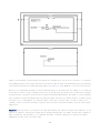
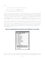
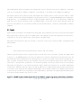
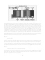
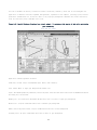
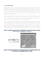
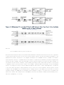
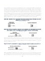
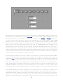
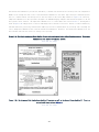
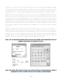
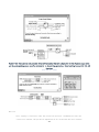
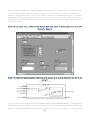
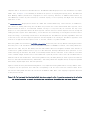
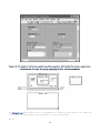
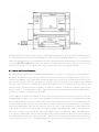
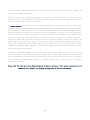
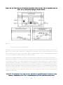
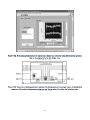
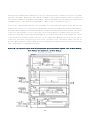
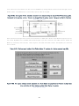
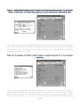
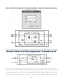
The most important rule with Booleans is to use them to represent parameters that have exactly two states that are logical
opposites—for example, On or Off, Yes or No, Open or Closed, and Stop or Go. When the two states are not opposites,
use a text ring or enumeration to provide text selections that more accurately describe the choices.
Rule 6.9
Assign names that identify the TRUE and FALSE value behavior
When a parameter's states are indeed opposites, it becomes easy to assign the control a name that clearly identifies
its behavior in relation to the TRUE and FALSE Boolean states. For example, if we have a control named Valve State,
the TRUE/FALSE behavior is unclear. Instead, consider a name such as Close Valve. In this case, we can determine from
the name that the valve is closed when TRUE and open when FALSE. Per Rule 3.23, always enter the default value in parentheses
for subVIs. This eliminates any chance of ambiguity. In the latter example, we have Close Valve (F = Open).
Rule 6.10
Use command buttons for action, slide switches for parameter settings
Use command buttons to represent Booleans that invoke immediate action on GUI VI panels, such as Trigger, Run, Cancel,
Quit, and Close Valve. Simply start with the OK, Cancel, or Stop button from the Boolean Controls palette, and customize
it for your needs. This may involve simply changing the Boolean text or editing the size, fonts, and colors as well.
Do not use command buttons for settings that do not generate immediate action, such as configuration properties. Instead,
[2]
use the control that appears most intuitive for the users. NI's Instrument Driver Guidelines
recommends the vertical
slide switch for all Boolean controls within an instrument driver. Most applications can be completed using just two
types of Boolean controls: command buttons for action on GUI VI panels, and vertical slide switches for configuration
parameters.
Rule 6.11
Label the TRUE and FALSE states of slide and toggle switches
Always label the TRUE and FALSE states of toggle and slide switches with names corresponding to the behavior of each
state, and position the labels next to the physical switch positions. Specifically, from the control's shortcut menu,
choose Advanced»Customize to open the Control Editor window. Drop free labels adjacent to each of the control's switch
positions and enter the text describing the TRUE and FALSE states. Edit the font, positions, and orientations of the
labels so that they line up with the TRUE and FALSE switch positions. Close the Control Editor window and apply the
custom changes. This method makes the label a permanent part of the control that you cannot accidentally move or delete
while editing the VI. A faster alternative is to display the control's Boolean text. Boolean text is made visible by
selecting Visible Items»Boolean Text from the control's shortcut menu, and it can be repositioned and edited. However,
the Boolean text shows only one state at a time and is not as intuitive as the TRUE and FALSE state labels.
Figure 6-6 provides a vertical toggle switch and command button for a valve control configured with three different
labeling schemes. The command button contains a glyph of a valve imported as a decal. In Figure 6-6A, the Valve State
control labels are ambiguous in terms of the TRUE/FALSE behavior. In Figure 6-6B, the Close Valve control labels clearly
depict the TRUE/FALSE behavior. Additionally, the vertical toggle switch contains visible Boolean text with default
175