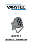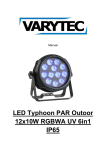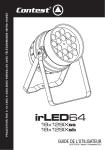
1
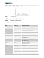
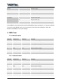
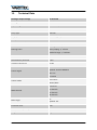
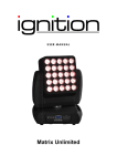
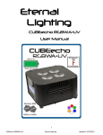
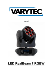
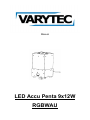
Manual LED Accu Penta 9x12W RGBWAU Table of contents 1. Safety instructions ............................................................................................................................ 3 1.1. FOR SAFE AND EFFICIENT OPERATION ............................................................................ 3 1.2. Additional Information for safety .............................................................................................. 4 2. Introduction ....................................................................................................................................... 5 2.1. Statement ................................................................................................................................ 5 2.2. Product description .................................................................................................................. 5 2.3. Features................................................................................................................................... 5 2.4. Charging and power instruction ............................................................................................... 6 3. Packaging ......................................................................................................................................... 6 4. Description of the display section..................................................................................................... 7 4.1. Structure of the menu .............................................................................................................. 7 5. DMX Chart ........................................................................................................................................ 8 5.1. 6 channel mode ....................................................................................................................... 8 5.2. 11 channel mode ..................................................................................................................... 8 5.3. 15 channel mode ................................................................................................................... 11 5.4. 18 channel mode ................................................................................................................... 12 6. IR remote control ............................................................................................................................ 15 6.1. Description ............................................................................................................................. 15 6.2. Master/Slave .......................................................................................................................... 17 7. Connecting ..................................................................................................................................... 18 7.1. XLR cable .............................................................................................................................. 18 7.2. The Conversion between 3 pin and 5 pin XLR ...................................................................... 18 7.3. Example ................................................................................................................................. 19 8. Trouble shooting............................................................................................................................. 20 9. Measurements................................................................................................................................ 21 10. Technical Data ........................................................................................................................... 22 2 / 24 1. Safety instructions This device is suitable for indoor use (not outdoors) only. All modifications to the device will void the warranty. Repairs are to carry out by skilled personnel only. Use only fuses of the same type and original parts as spare parts. Protect the unit from rain and humidity to avoid fire and electric shocks. Make sure to unplug the power supply before opening the housing. 1.1. FOR SAFE AND EFFICIENT OPERATION Be careful with heat and extreme temperature Avoid exposing it to direct rays of the sun or near a heating appliance. Not put it in a temperature bellow 32°F /0°C, or exceeding 104°F /40°C. Keep away from humidity, water and dust Do not place the set in a location with high humidity or lots of dust. Containers with water should not be placed on the set. Keep away from sources of hum and noise Such as transformer motor, tuner, TV set and amplifier. To avoid placing on un-stable location Select a level and stable location to avoid vibration. Do not use chemicals or volatile liquids for cleaning Use a clean dry cloth to wipe off the dust, or a wet soft cloth for stubborn dirt. If out of work, contact sales agency immediately Any troubles arose, remove the power plug soon, and contact with an engineer for repairing, do not open the cabinet by yourself, it might result a danger of electric shock. Take care with the power cable Never pull the power cable to remove the plug from the receptacle, be sure to hold the plug. When not using the device for an extended period of time, be sure to disconnect the plug from the receptacle. 3 / 24 Important: Damages caused by the disregard of this user manual are not subject to warranty. The dealer will not accept liability for any resulting defects or problems. Make sure the electrical connection is carried out by qualified personnel. All electrical and mechanical connections have to be carried out according to the European safety standards. 1.2. Additional Information for safety Exessive temperature Ta=40°C Please do not use the device if the temperature exceeds 40°C/104°F. Drop safety To avoid injuries carry the package only by twos. If you install the device the mounting bracket has the ability to carry the tenfold load of the weight of the device. Always use a corresponding safety to safe the device additional. While working at the device the place below has to be vacated Beware of electrical shock Make sure the electrical connection is carried out by qualified personnel. Before you plug in the device make sure that the power supply system has the right voltage and also a crowbar. Every device has to be grounded. Unplug the power supply if you want to change a lamp or you have to open the device. You also have to accomplish this action if there is a thunderstorm or high humidity. Fire risk Make sure that the fuse functioned. It is never allowed to bridge it. If you have to exchange it only use fuses of the same type. It is not allowed cover fans and air in and outlets. Make sure that there is a distance between the device and all objects in an area of 0.5m. Don’t put or mount anything on the lens. The device has to cool down for 20 minutes before opening. 4 / 24 2. Introduction 2.1. Statement Thank you for purchasing the LED Accu Penta. Please read these instructions carefully before begin and operate the fixtures according to these instructions to avoid any possible damages and accidents causes by misusage. 2.2. Product description This product has a light body and fashion design. It uses high power 6-in-1 LED, which means each LED is made of R, G, B, A, W,V LED chips. Long life span, low power consumption, good color mixing effect and high brightness are the most prominent features. Each kind of LED can be independently dimmed. The built-in program includes dimming, strobe, gradual change, fading and so on. It uses lithium battery power supply, stable capability and easy to carry. International standard DMX 512 signal is requested. 2.3. Features High quality LED: low consumption, high brightness, stable capability and long life Each color of LED with 32-bit, 16666 grades dimming. 600Hz dimming frequency, take pictures without flicker DMX512 Controller,4 button set DMX ID address with LCD display Dim 0%-100%, Strobe、gradual change、jumping change and etc DMX512 Controller,2 layers LEDs, under layer: 3 pcs. LEDs, upper layer: 6 pcs. LEDs, could be controlled alone between layers Auto run/master slave/interconnected multi-machine control Optional: Wireless DMX control Electric quantity display Lithium battery power supply, stable capability and easy to carry IR remote control function Power charging indicator Output mode optional Lens degree: 25º、45º optional Output Mode:H (100%), M (75%), S (50%) DMX Controller channel optional IP20 5 / 24 2.4. Charging and power instruction When charging, CHARGE LED red. Full power LED green. LCD display electric quantity, please off fixture and battery charging when display no power. It is not good at usage life of battery, please avoid to using fixture when charging. And avoid overcharge, charging time is about 4 hours. Total 5 bars for power display. One bar = 20% power. 3. Packaging To every device belong the following accessories. LED Accu Penta 1 pcs. DMX signal cable 1 pcs. Power-in cable 1 pcs. User manual 1 pcs. 6 / 24 4. Description of the display section MENU: Access the menu UP: Menu selection or parameter increments DOWN: Menu selection or parameters decrease ENTER: Confirm the current menu option 4.1. Structure of the menu Menu Function set Function description Addr 001‐512 Setting the DMX address CHnd 6CH DMX mode with 6 DMX channels 11CH DMX mode with 11 DMX channels 15CH DMX mode with 15 DMX channels 18CH DMX mode with 18 DMX channels AUTO 00‐64 Automatic programs Speed 00‐15 Adjusts the speed for the automatic programs. 00 = fast, 15 = slow Fade 00‐15 Adjusts the gradual changing speed 00 = fast, 15 = slow Strobe 00‐15 Adjusts the strobe speed 00 = fast, 15 = slow Manual RED 000‐255 Dimmer red GREEN 000‐255 Dimmer green BLUE 000‐255 Dimmer blue AMBER 000‐255 Dimmer amber WHITE 000‐255 Dimmer white UV 000‐255 Dimmer UV 7 / 24 Sound … Sound‐to‐Light Dimmer 0‐4 Adjusts the DMX dimmer mode RF_ID 1‐7 Wireless ID set IR MODE IR receive mode OUTMOD H Output mode 100% M Output mode 75% S Output mode 50% Press MENU to reach the first menu and use UP/DOWN to get to the submenu. To open the submenu you have to press ENTER, here you can reach other menu items with UP/DOWN, confirm with ENTER. Press MENU to store your settings. 5. DMX Chart 5.1. 6 channel mode Channel Value from Value to Function 1 000 255 Dimmer red 0‐100% 2 000 255 Dimmer green 0‐100% 3 000 255 Dimmer blue 0‐100% 4 000 255 Dimmer amber 0‐100% 5 000 255 Dimmer white 0‐100% 6 000 255 Dimmer UV 0‐100% 5.2. 11 channel mode Channel Value from Value to Function 1 000 255 Dimmer 0‐100% 2 000 255 Dimmer red 0‐100% 3 000 255 Dimmer green 0‐100% 4 000 255 Dimmer blue 0‐100% 5 000 255 Dimmer amber 0‐100% 6 000 255 Dimmer white 0‐100% 7 000 255 Dimmer UV 0‐100% 8 / 24 000 010 Strobe off 011 255 Strobe slow‐fast 000 015 General dimming 016 018 Red 019 021 Green 022 024 Blue 025 027 Amber 028 030 White 031 033 UV 034 036 Red + Green 037 039 Red + Blue 040 042 Red + Amber 043 045 Red + White 046 048 Red + UV 049 051 Green + Blue 052 054 Green + Amber 055 057 Green + White 058 060 Green + UV 061 063 Blue + Amber 064 066 Blue + White 067 069 Blue + UV 070 072 Amber + White 073 075 Amber + UV 076 078 White + UV 079 081 Red + Green + Blue 082 084 Red + Green + Amber 085 087 Red + Green + White 088 090 Red + Green + UV 091 093 Red + Blue + Amber 094 096 Red + Blue + White 097 099 Red + Blue + UV 8 9 9 / 24 100 102 Red + Amber + White 103 105 Red + Amber + UV 106 108 Red + White + UV 109 111 Green + Blue + Amber 112 114 Green + Blue + White 115 117 Green + Blue + UV 118 120 Green + Amber + White 121 123 Green + Amber + UV 124 126 Green + white + UV 127 129 Blue + Amber + White 130 132 Blue +Amber + UV 133 135 Blue + White + UV 136 138 Amber + White + UV 139 141 Red + Green + Blue + Amber 142 144 Red + Green + Blue + White 145 147 Red + Green + Blue + UV 148 150 Red + Green + Amber + White 151 153 Red + Green + Amber + UV 154 156 Red + Green +White + UV 157 159 Red + Blue + Amber + White 160 162 Red + Blue + Amber + UV 163 165 Red + Blue + White + UV 166 168 Red + Amber + White + UV 169 171 Green + Blue + Amber + White 172 174 Green + Blue + Amber + UV 175 177 Green + Blue + White+ UV 178 180 Green + Amber + White UV 181 183 Blue + Amber + White + UV 184 186 Red + Green +Blue + Amber + White 187 189 Red + Green + Blue + Amber + UV 190 192 Red + Green + Blue + White + UV 10 / 24 193 195 Red + Green + Amber + White + UV 196 198 Red + Blue + Amber + White + UV 199 201 Green + Blue + Amber + White + UV 202 204 Red + Green + Blue + Amber + White + UV 205 229 Auto run 1 slow‐fast 230 255 Auto run 2 slow‐fast 000 015 No function 016 255 Gradual changing mode slow‐fast 000 005 Set by LED display Dimmer 0‐4 006 055 Dimmer 0 056 105 Dimmer 1 106 155 Dimmer 2 156 205 Dimmer 3 206 255 Dimmer 4 10 11 5.3. 15 channel mode Channel Value from Value to Function 1 000 255 Dimmer Red 1 2 000 255 Dimmer Green 1 3 000 255 Dimmer Blue 1 4 000 255 Dimmer Amber 1 5 000 255 Dimmer White 1 6 000 255 Dimmer UV 1 7 000 255 Dimmer Red 2 8 000 255 Dimmer Green 2 9 000 255 Dimmer Blue 2 10 000 255 Dimmer Amber 2 11 000 255 Dimmer White 2 12 000 255 Dimmer UV 2 000 010 Strobe off (first layer) 011 255 Strobe speed slow‐fast (first layer) 13 11 / 24 000 010 Strobe off (second layer) 011 255 Strobe speed slow‐fast (second layer) 000 005 Set by LED display dimmer 0‐4 006 055 Dimmer 0 056 105 Dimmer 1 106 155 Dimmer 2 156 205 Dimmer 3 206 255 Dimmer 4 14 15 5.4. 18 channel mode Channel Value from Value to Function 1 000 255 Dimmer 0‐100% 2 000 255 Dimmer Red 1 3 000 255 Dimmer Green 1 4 000 255 Dimmer Blue 1 5 000 255 Dimmer Amber 1 6 000 255 Dimmer White 1 7 000 255 Dimmer UV 1 8 000 255 Dimmer Red 2 9 000 255 Dimmer Green 2 10 000 255 Dimmer Blue 2 11 000 255 Dimmer Amber 2 12 000 255 Dimmer White 2 13 000 255 Dimmer UV 2 000 010 Strobe off (first layer) 011 255 Strobe speed slow‐fast (first layer) 000 010 Strobe off (second layer) 011 255 Strobe speed slow‐fast (second layer) 000 015 General dimming 016 018 Red 019 021 Green 14 15 16 12 / 24 022 024 Blue 025 027 Amber 028 030 White 031 033 UV 034 036 Red + Green 037 039 Red + Blue 040 042 Red + Amber 043 045 Red + White 046 048 Red + UV 049 051 Green + Blue 052 054 Green + Amber 055 057 Green + White 058 060 Green + UV 061 063 Blue + Amber 064 066 Blue + White 067 069 Blue + UV 070 072 Amber + White 073 075 Amber + UV 076 078 White + UV 079 081 Red + Green + Blue 082 084 Red + Green + Amber 085 087 Red + Green + White 088 090 Red + Green + UV 091 093 Red + Blue + Amber 094 096 Red + Blue + White 097 099 Red + Blue + UV 100 102 Red + Amber + White 103 105 Red + Amber + UV 106 108 Red + White + UV 109 111 Green + Blue + Amber 112 114 Green + Blue + White 13 / 24 115 117 Green + Blue + UV 118 120 Green + Amber + White 121 123 Green + Amber + UV 124 126 Green + white + UV 127 129 Blue + Amber + White 130 132 Blue +Amber + UV 133 135 Blue + White + UV 136 138 Amber + White + UV 139 141 Red + Green + Blue + Amber 142 144 Red + Green + Blue + White 145 147 Red + Green + Blue + UV 148 150 Red + Green + Amber + White 151 153 Red + Green + Amber + UV 154 156 Red + Green +White + UV 157 159 Red + Blue + Amber + White 160 162 Red + Blue + Amber + UV 163 165 Red + Blue + White + UV 166 168 Red + Amber + White + UV 169 171 Green + Blue + Amber + White 172 174 Green + Blue + Amber + UV 175 177 Green + Blue + White+ UV 178 180 Green + Amber + White UV 181 183 Blue + Amber + White + UV 184 186 Red + Green +Blue + Amber + White 187 189 Red + Green + Blue + Amber + UV 190 192 Red + Green + Blue + White + UV 193 195 Red + Green + Amber + White + UV 196 198 Red + Blue + Amber + White + UV 199 201 Green + Blue + Amber + White + UV 202 204 Red + Green + Blue + Amber + White + UV 205 229 Auto run 1 slow‐fast 14 / 24 230 255 Auto run 2 slow‐fast 000 015 No function 016 255 Gradual changing mode slow‐fast 000 005 Set by LED display Dimmer 0‐4 006 055 Dimmer 0 056 105 Dimmer 1 106 155 Dimmer 2 156 205 Dimmer 3 206 255 Dimmer 4 17 18 6. IR remote control 6.1. Description If you want to use the IR remote the device must be set for IR remote control. 15 / 24 Press the button; fixture off, ready mode Press the button, auto run mode, and pre SPEED could adjust the auto run speed Press the button, sound activated Press the button, strobe mode, and press SPEED could adjust the strobe speed Press the button, built in program mode, could adjust built in program pattern Press the button, DMX control mode Press the button, adjust auto run speed and strobe speed Press the button, slave mode Press the button, set DMX address code, press”+” and “‐“ to adjust, press ENTER to store; then press ”D”, DMX receiving mode, could receive DMX signal Press the button, could change DMX address and manual dimming value Press the button, start LCD backlight, auto off 20 seconds later Press the button, could change DMX address and manual dimming value Press the button and “+” “‐“, could adjust red intensity(1‐6 color effect could mixing, user defined) Press the button and “+” “‐“, could adjust green intensity(1‐6 color effect could mixing, user defined) Press the button and “+” “‐“, could adjust blue intensity(1‐6 color effect could mixing, user 16 / 24 defined) Press the button and “+” “‐“, could adjust Amber intensity(1‐6 color effect could mixing, user defined) Press the button and “+” “‐“, could adjust white intensity(1‐6 color effect could mixing, user defined) Press the button and “+” “‐“, could adjust UV intensity(1‐6 color effect could mixing, user defined) Press the button, full bright mode Press the button, Red + Blue Press the button, Green + Blue Press the button to “IR MODE” Press the button to UV Press the button for store 6.2. Master/Slave Master setting: The master should be one of following modes: built-in modes, color jumping Mode, fade mode, white strobe mode and auto dimming mode. It sends out synchronizing signal. To avoid the master signal and DMX512 signal from interfering with each other, we should cut off the DMX512 signal. When the signal cables are longer than 60 meters, a DMX signal amplifier is necessary. Slave setting:It must be in DMX mode, address code is 001 and CHnd is 15Ch to assure receiving the master’s signals correctly. Only one light can be set as a Master and others are slaves. 17 / 24 7. Connecting 7.1. XLR cable The standard way of connecting the XLR is: one end connects to the male plug, and the other end connects to the female. As below: Pin 1 = ground Pin 2 = negative signal Pin 3 = positive signal Noted:In order to avoid failures and interference signal transmission,we connect a resistance 120Ω (1/4W) at the end of the DMX connecting as below: 7.2. The Conversion between 3 pin and 5 pin XLR If the output cable of DMX512 controller is the 5PIN, please use 1pc 5PIN to 3PIN cable 18 / 24 7.3. Example 19 / 24 8. Trouble shooting Problem Checking Way Cannot turn the light on. Check if the power source plug is in normal or not. Check if the switch of the lights is off or on. Check if the fuse if in normal. DMX cannot control it. Check if the DMX cable is connected to the lights or not. Check if the DMX512 controller works normal or not. Check if the DMX cable is normal or not. Check if the lights are in DMX mode (e.g. A001). Display not bright. When connect to the electricity, did the LED flash one time? If so, the power source is normal. If not, please contact your supplier. LED not light. When connect to the electricity, did the LED flash one time? If so, the power source is normal. If not, please contact your supplier Some of the LED not light. Please contact your supplier. Single color LEDs always bright/not bright. Please contact your supplier. 20 / 24 9. Measurements 21 / 24 10. Technical Data Recharger output voltage DC 29.4V 2A Recharge time Ca. 4 hours Input voltage AC 100‐240V; 50‐60Hz Power 108W Lamp Type LED 12W Lamp Spec 6in1 LED (9 pcs.) Life span 50000‐100000 hours Constant current driver 400mA Full brightness: +/‐ 3 hours Running hours Color jumping: +/‐ 5 hours Gradual change: +/‐ 10 hours PWM Dimmer 600Hz Anti‐electricity intension 1.5KV Insulation Resistance >2 MΩ Wire Control Signal Optional: wireless DMX512 Auto run IR remote Control mode Stand alone Master/Slave 6 channels DMX channels 11 channels 15 channels 18 channels Beam angle 25° Optional: 45° Protection class IP20 Measurements (LxWxH) 173x173x318.8mm Weight 5kg 22 / 24 23 / 24 Importer: B & K Braun GmbH Industriestraße 2 D-76307 Karlsbad www.bkbraun.com [email protected] 24 / 24