1
FAVOR ● FAVOR LUX ●
FAVOR LUX S (FUSION)
User’s Manual
PDF Version
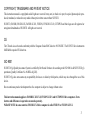
Quick Reference Guide
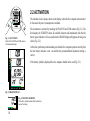
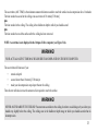
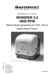
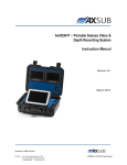
Arrows:
Decompression Stop in the Ceiling Zone
Ascent Recommended
Must Descend
Ascent Rate Indicator
A
S
C
R
A
T
E
Current Time Display
Surface Interval/ No Flying Time
No-Decompression Time
Ceiling Depth/ Total Ascent Time
(See Note)
Common Contact
Temperature
Dive Counter
Maximum Depth During Diving
Day of the Month
Multifunctional Bar Graph:
Mode Indicator
Battery Power Indicator
Reverse No-Decompression Time
2
m
MAX
CEILING
ASC TIME
SURF TIME NO DEC TIME
MAX DIVE
DIVE
CF
TIME
LOG
HIS
ALT
SET
Time Display/
Mode Selection Contact
NO
A0
A1
A2
COM
Present Depth
Maximum Depth at the Surface
Fast Ascent Warning (SLOW)
Average Depth in the Logbook Mode
PLAN
TIME
MODE
Personal Adjustment/
Altitude Adjustment Mode
PLAN
ON
Activation/ Dive Planning
Contact
Low Battery Warning
Dive Time
Month
COPYRIGHT, TRADEMARK AND PATENT NOTICE
This instruction manual is copyrighted and all rights are reserved. It may not, in whole or in part, be copied, photocopied, reproduced, translated, or reduced to any media without prior written consent from SUUNTO.
SUUNTO, FAVOR, FAVOR LUX, FAVOR LUX S, FUSION, FUSION LUX S, OCTOPUS and their logos are all registered or
unregistered trademarks of SUUNTO. All rights are reserved.
CE
The CE mark is used to mark conformity with the European Union EMC directive 89/336/EEC. The SUUNTO dive instruments
fulfill all the required EU directives.
ISO 9001
SUUNTO Oyj's Quality Assurance System is certified by Det Norske Veritas to be according to the ISO 9001 in all SUUNTO Oyj's
operations (Quality Certificate No. 96-HEL-AQ-220).
SUUNTO Oyj does not assume any responsibility for losses or claims by third parties, which may arise through the use of this
device.
Due to continuous product development the dive computer is subject to change without notice.
This instruction manual applies to FAVOR/LUX/LUX S, FUSION/LUX S and OCTOPUS II dive computers. Extra
features and differences in operation are noted separately.
PLEASE NOTE: In some countries FAVOR LUX S dive computer is called FUSION or FUSION LUX S.
3
DEFINITION OF WARNINGS, CAUTIONS AND NOTES
Throughout this manual, special references are made when deemed important. Three classifications are used to separate these
references by their order of importance.
WARNING
- is used in connection with a procedure or situation that may result in serious injury or death.
CAUTION
- is used in connection with a procedure or situation that will result in damage to the product.
NOTE
- is used to emphasize important information.
WARNING!
READ THIS MANUAL! Carefully read this instruction manual in its entirety, including Section 1, “For Your Safety”. Make sure
that you fully understand the use, displays and limitations of this dive computer. Any confusion resulting from improper use of
this device may cause diver to commit errors that may lead to serious injury or death.
WARNING!
ONLY DIVERS TRAINED IN THE PROPER USE OF SCUBA EQUIPMENT SHOULD USE THIS DIVE COMPUTER! No
dive computer can replace the need for proper dive training. Insufficient or improper training may cause diver to commit errors
that may lead to serious injury or death.
WARNING!
PERFORM PRECHECKS! Always check this instrument before diving in order to ensure that all LCD segments are completely
displayed, that the dive computer has not run out of battery power, and that the personal and altitude adjustment mode is correct.
4
WARNING!
USE BACK-UP INSTRUMENTS! Make certain that you use back-up instrumentation including a depth gauge, submersible
pressure gauge, timer or watch, and have access to decompression tables whenever diving with this instrument.
WARNING!
NO DIVE COMPUTER WILL PREVENT THE POSSIBILITY OF DECOMPRESSION SICKNESS (DCS)! All divers must
understand and accept that there is no procedure or dive computer that will totally prevent the possibility of a decompression
accident. For example, the individual physiological make up can vary within an individual from day to day. The dive computer
cannot account for these variations. As an added measure of safety, you should consult a physician regarding your fitness before
diving. Decompression sickness can cause serious injury or death.
WARNING!
NOT FOR PROFESSIONAL USE! SUUNTO dive computers are intended for recreational use only. The demands of commercial or professional diving often expose the diver to depths and prolonged exposures including multiday exposures that tend to
increase the risk of decompression sickness. Therefore, Suunto specifically recommends that this instrument is not used for
commercial or other severe diving activity.
5
TABLE OF CONTENTS
QUICK REFERENCE GUIDE ........................................................................................................ 2
INTRODUCTION ............................................................................................................................ 8
1. FOR YOUR SAFETY ............................................................................................................... 10
2. GETTING ACQUAINTED WITH THE INSTRUMENT........................................................ 17
2.1 WATER CONTACTS ....................................................................................................................................... 17
2.2 ACTIVATION ................................................................................................................................................... 18
3. DIVING WITH THE DIVE COMPUTER ................................................................................ 19
3.1 USE OF WATER CONTACTS ........................................................................................................................ 19
3.2 LUX/LUX S MODELS: TAP SWITCH AND ELECTROLUMINESCENT BACKLIGHT ...................... 21
3.3 BEFORE DIVING ............................................................................................................................................ 22
3.3.1 Activation, Prechecks and Battery Warning .............................................................................................. 22
3.3.2 Dive Planning ............................................................................................................................................ 25
3.3.3 Calendar Clock Function ........................................................................................................................... 26
3.4 DIVING ............................................................................................................................................................ 27
3.4.1 Basic Dive Data ......................................................................................................................................... 27
3.4.2 Reverse No-Decompression Time Bar Graph ........................................................................................... 28
3.4.3 Ascent Rate Indicator ................................................................................................................................ 29
3.4.4 Alarms ....................................................................................................................................................... 31
3.4.5 Decompression Dives ................................................................................................................................ 32
6
3.5 AT SURFACE ................................................................................................................................................... 36
3.5.1 Surface Interval ......................................................................................................................................... 36
3.5.2 Flying After Diving ................................................................................................................................... 38
3.6 PERSONAL ADJUSTMENT AND HIGH ALTITUDE DIVES .................................................................. 39
3.7 ERROR CONDITIONS ................................................................................................................................... 41
4. MENU BASED MODES ........................................................................................................... 43
4.1 LOGBOOK MEMORY .................................................................................................................................... 44
4.2 DIVE HISTORY MEMORY ........................................................................................................................... 47
4.3 PERSONAL/ALTITUDE ADJUSTMENT SETTING .................................................................................. 48
4.4 SETTING TIME AND DATE ......................................................................................................................... 50
5. CARE AND MAINTENANCE ................................................................................................. 52
5.1 MAINTENANCE ............................................................................................................................................. 53
5.2 BATTERY COMPARTMENT INSPECTION ............................................................................................... 54
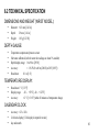
6. TECHNICAL DESCRIPTION .................................................................................................. 55
6.1 OPERATING PRINCIPLES ............................................................................................................................ 55
6.2 TECHNICAL SPECIFICATION ..................................................................................................................... 61
7. WARRANTY ............................................................................................................................. 63
8. GLOSSARY ............................................................................................................................... 64
7
INTRODUCTION
Congratulations on your choice of the SUUNTO Dive Computer.
It is a compact and sophisticated dive instrument that will give you years of trouble free and joyful diving. The dive computer will
provide you with important information that you will need during, between, and after your dives.
KEY FEATURES
The dive computer monitors and reports vital information such as your dive time, current depth, maximum depth, no-decompression time and ascent rate.
The dive computer will also give you information, if through carelessness or emergency you are forced to exceed the no-decompression limits for any dive.
The instrument has a built-in calendar and clock. It features versatile logbook memory capabilities and long-term historical data.
The instrument can be adjusted for diving at different altitudes or to add an extra level of conservativeness if desired.
The screen is protected against scratches and damage by a replaceable shield.
The dive computer is available either as a wrist unit with an optional protective boot or mounted in two gauge or three gauge console
or in a hose mounted boot. The modular construction allows for the separate compass module to be attached to the two gauge
console at a later stage.
8
METRIC AND IMPERIAL UNITS
All examples in this manual are shown in metric units, including meters and °C. The corresponding imperial units are shown in
brackets. The instrument is also available with imperial units, i.e. feet and °F.
WARNING!
VERIFY THAT THE UNITS OF MEASURE, WHETHER METRIC OR IMPERIAL, ARE CORRECT BEFORE STARTING
TO DIVE! Any confusion resulting from improper selection of units may cause the diver to commit errors that may lead to
serious injury.
9
1. FOR YOUR SAFETY
Always remember that THE DIVER IS RESPONSIBLE FOR HIS OR HER OWN SAFETY!
When used properly this dive computer is an outstanding tool for assisting properly trained, certified divers in planning and executing standard and multi-level sport dives within the described no-decompression limits. It is NOT A SUBSTITUTE FOR CERTIFIED SCUBA INSTRUCTION including training in the principles of decompression.
DO NOT attempt to use this dive computer without reading this entire Instruction Manual. If you have any questions about the
manual or the instrument itself, contact your Suunto dealer before diving with the dive computer.
BACK-UP INSTRUMENTS
WARNING!
USE BACK-UP INSTRUMENTS! Make certain that you use back-up instrumentation including a depth gauge, submersible
pressure gauge, timer or watch, and have access to decompression tables whenever diving with this dive computer.
10
SHARING THE DIVE COMPUTER
WARNING!
THE DIVE COMPUTER SHOULD NEVER BE TRADED OR SHARED BETWEEN USERS WHILE IT IS IN OPERATION!
Its information will not apply to someone who has not been wearing it throughout a dive or sequence of repetitive dives. Its dive
profiles must match that of the user. If it is left on the surface during any dive, it will give inaccurate information for subsequent
dives.
No dive computer can take into account dives made without the computer. Thus any diving activity 48 hours prior to initial use of
the computer may give misleading information and must be avoided.
11
PERSONAL/HIGH ALTITUDE ADJUSTMENT
More information about this is given in Section 3.6, “Personal Adjustment and High Altitude Dives”.
WARNING!
SET THE CORRECT PERSONAL/ALTITUDE ADJUSTMENT MODE! When diving at altitudes greater than 700 m [2300 ft]
the personal/altitude adjustment feature must be correctly selected in order for the computer to calculate no-decompression
status. The diver should also use this option to make the calculation more conservative, whenever it is believed that factors which
tend to increase the possibility of decompression sickness exist (see Section 3.6). Failure to properly select the personal/altitude
adjustment mode correctly will result in erroneous data and can greatly increase the risk of decompression sickness.
WARNING!
THE INSTRUMENT IS NOT INTENDED FOR USE AT ALTITUDES GREATER THAN 2400 m [8000 ft]! Diving at altitudes
above this limit may significantly increase the risk of decompression sickness.
When diving at higher altitudes (above 700 m / 2300 ft), it is essential that the entered altitude mode, i.e. maximum altitude limit of
the dive computer, exceeds or is equal to the altitude of the dive site. The altitude mode indicator must show either A1 or A2,
depending on the altitude. More information about this is given in Section 3.6, “Personal Adjustment and High Altitude Dives”.
12
DECOMPRESSION DIVES
WARNING!
DO NOT USE THIS INSTRUMENT TO CONDUCT DECOMPRESSION DIVES! Suunto does not recommend this instrument
to be used to conduct decompression dives. However, if through carelessness or emergency a diver is forced to exceed the nodecompression limits on a dive, the instrument will provide decompression information required for ascent. After this the dive
computer will continue to provide subsequent interval and repetitive dive information.
EMERGENCY ASCENTS
In the unlikely event that the instrument malfunctions during a dive, follow the emergency procedures provided by your certified
dive training agency or, alternatively, immediately ascend at a rate slower than 10 m/min [33 ft/min] to a depth between 3 and 6
meters [10 to 20 ft] and stay there as long as your air supply will safely allow.
13
HIGHER RISK DIVE PROFILES
The user must understand that all decompression devices (decompression tables and/or dive computers) are based on mathematical
models and that many experts are currently concerned that these models may not under certain conditions adequately describe the
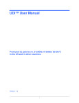
physiological phenomena. These conditions are presently identified as dives which incorporate the following (Fig. 1.1):
• SAWTOOTH PROFILES
throughout the dive.
where the diver alternates between greater and shallower depths repeatedly
• REVERSE PROFILES
where the diver spends most of the dive at shallow depths and then descends
to the maximum depth shortly before surfacing.
• CONSECUTIVE DIVES
where the diver performs repetitive dives to approximately the same maximum
depth with only short surface intervals between dives. The risk of decompres
sion sickness increases when depth and the number of repetitive dives
increase and
when the surface intervals are decreased.
• MULTIDAY DIVES
repetitive dives performed for several consecutive days.
• DECOMPRESSION DIVES
any dive during which the no-decompression limit has been exceeded or the
diver is advised by the computer that he may not return directly to the surface.
14
WARNING!
DIVE PRACTICES WHICH INCLUDE THE ABOVE DESCRIBED “HIGHER RISK DIVE PROFILES” ARE BELIEVED TO
INCREASE THE RISK OF DECOMPRESSION SICKNESS AND AS SUCH CONSIDERED POTENTIALLY DANGEROUS
AND SHOULD BE AVOIDED EVEN IF THEY CONFORM TO THE MATHEMATICAL MODEL!
WARNING!
DO NOT USE THE DIVE COMPUTER WITH NITROX MIX! The mathematical tissue calculation model of the instrument has
been designed for use with standard breathing air only (approximately 21% oxygen and 79% nitrogen by volume). Therefore, the
dive computer must not be used for diving with “Nitrox” or other mixed gases.
time
Consecutive dives
Fig. 1.1 HIGHER RISK DIVE PROFILES
time
depth
depth
time
depth
time
depth
Multiday dives
Reverse profiles
Sawtooth profiles
Fig. 1.2 RECOMMENDED PROFILE
15
DIVE COMPUTER LIMITATIONS
While the instrument is based on current decompression research and technology, the user/ diver must realize that the computer
cannot monitor the actual physiological functions of an individual diver. All decompression schedules currently known to the
authors, including the U.S. Navy Tables, are based on a theoretical mathematical model which is intended to serve as a guide to
reduce the probability of decompression sickness.
The mathematical model uses an ascent rate of 10 m/min [33 ft/min]. Therefore it is critical that a proper ascent rate is always used.
The reader/diver is forewarned that individual physiological differences, severe environmental conditions and predive activities,
especially those which tend to increase dehydration, may increase the risk of decompression sickness.
As a safety precaution Suunto recommends that divers using this instrument should maintain no less than 10 minutes no-decompression time remaining at all times during the dive. This is especially important for divers in poor physical condition, in cold water
or other arduous conditions.
Historically divers have been advised to always include a margin of safety in their diving activities. Suunto supports these practices
and strongly recommends that the diver make the deepest portion of the dive near the beginning of the dive and gradually progress
into shallower depth, allowing time for a 3 to 5 minutes “safety stop” at a depth range of 3 to 6 meters (10 to 20 ft). This is believed
to be effective in further reducing the risk of decompression sickness.
Furthermore, the reader/diver is advised that any dive carries some risk of decompression sickness and neither the authors, nor
SUUNTO Oyj will assume any responsibility or liability for accidents or injuries which might occur for any reason.
16
2. GETTING ACQUAINTED WITH THE DIVE COMPUTER
WARNING!
READ AND UNDERSTAND THE ENTIRE OWNER’S MANUAL BEFORE DIVING! Failure to complete this step may result
in serious personal injury.
The purpose of this section is to provide the user with initial information to preview the operation of the computer. Since this
information is limited, it is imperative that you read and understand the entire owner’s manual before attempting to dive.
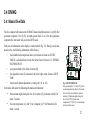
2.1 WATER CONTACTS
The dive computer has three water contacts on the face of the instrument:
• COM:
common contact
• PLAN/ON:
• TIME/MODE:
activation and dive planning contact
time display and mode selection contact
On the surface the instrument is operated by simultaneously touching the COM contact and one or two of the other contacts. When
doing this, your finger tips should be wet or moist to establish the necessary electric contact. When submerged these contacts are
automatically connected by the conductivity of the water.
17
A
S
C
R
A
T
E
ASC TIME
CEILING
NO
A0
A1
A2
TIME
MODE
SURF TIME NO DEC TIME
MAX DIVE
DIVE
CF
TIME
COM
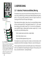
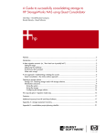
2.2 ACTIVATION
m
MAX
LOG
HIS
ALT
SET
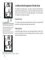
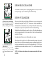
The calendar clock is always shown on the display, when the dive computer is deactivated.
In this mode the power consumption is minimal.
PLAN
ON
PLAN
Fig. 2.1 ACTIVATION
Touch the PLAN/ON and COM contacts
with moistened fingers.
A
S
C
R
A
T
E
m
MAX
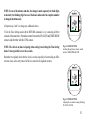
The instrument is activated by touching the PLAN/ON and COM contacts (Fig 2.1). The
first display, the STARTUP, shows all available elements and immediately after this the
battery power indicator. A few seconds later the READY display will appear, showing zero
values (Fig. 2.2).
At this time, perform a precheck making sure that the dive computer operates correctly, that
the low battery indicator is not on and that the personal/altitude adjustment setting is
correct.
If the battery symbol is displayed the dive computer should not be used (Fig. 2.3).
A1
SURF TIME
MAX
m
DIVE
TIME
C
LOG
HIS
ALT
SET
PLAN
Fig. 2.2 READYA1
DISPLAY
SURF TIME
DIVE
TIME
C
LOG
HIS
ALT
18
SET
PLAN
Fig. 2.3 BATTERY WARNING
The battery symbol indicates that the battery is
too low for diving.
3. DIVING WITH THE DIVE COMPUTER
This section contains instructions on how to operate the dive computer and interpret its
displays. Each display has been carefully designed to provide important information you
will need to plan your dive or dive series.
You will find that the ínstrument is easy to use and read. Each display shows only the data
relevant to that specific diving situation. For example, while you are on a dive, surface
interval data is irrelevant and therefore not shown. On the other hand, while you are on the
surface after a dive, remaining no-decompression time for that dive is irrelevant and therefore replaced with information for your next dive.
3.1 USE OF WATER CONTACTS
As described in Section 2.1, “Water Contacts”, the dive computer is controlled with the
COM (common), PLAN/ON, and TIME/MODE contacts (Fig 3.1), as follows:
Activation:
touch the PLAN/ON and COM contacts.
Dive planning:
once the instrument has been activated, touch
the PLAN/ON and COM contacts.
Clock:
once the instrument has been activated, touch the
TIME/MODE and COM contacts for two seconds.
The
time is then displayed for four seconds.
Fig. 3.1 USING THE WATER
CONTACTS
a) Activation and dive planning
b) Time display and menu based modes
c) Exit the modes
19
When the TIME/MODE and COM contacts are touched for over three seconds, the display will start to scroll through the following
modes. Lift your fingers when the desired mode is displayed:
Logbook memory:
at LOG the logbook memory is accessed.
Dive history memory:
at HIS the history memory is accessed.
Personal/altitude adjustment setting:
at Alt the personal and/or altitude adjustment can be set.
Time setting:
at Set the time and date can be adjusted.
Return:
you can at any time exit the above modes by touching all three contacts at the
same time. First make contact between the PLAN/ON and TIME/MODE
contacts, e.g. by covering both contacts with your right thumb. Without
lifting your right thumb, touch the COM contact with your left thumb.
Alternatively, you can exit the modes simply by submerging the dive computer
in water.
You may sometimes encounter problems in using the contacts, or the instrument may activate on its own. The reason for this is
probably contamination or invisible marine growth that may create an unwanted electric current between the water contacts. It is
therefore important that the dive computer be carefully washed in fresh water after the day’s diving is completed. The contacts can
be cleaned with a soft pencil eraser.
20
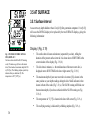
3.2 LUX/LUX S MODELS: TAP SWITCH AND
ELECTROLUMINESCENT BACKLIGHT
The tap switch is used to activate the electroluminescent backlight. The switch is used by
pressing or tapping the movement sensitive area with your finger. This area is on the face
of the instrument between the ON/PLAN and TIME/MODE water contacts marked with a
“¤ LUX” symbol.
The light can be activated in all modes when the computer is on. The illumination goes off
automatically after approximately 10 seconds from activation. With a little practicing you
will quickly figure out how to use the tap switch. Do the practicing in a dark room so you
can see when the light goes on.
NOTE: For safety reasons the lamp will not come on, if the battery voltage is low
(the low battery symbol is displayed).
A
S
C
R
A
T
E
m
TIME
MODE
PLAN
ON
COM
LOG
HIS
ALT
SET
PLAN
Fig. 3.2 ACTIVATING THE
BACKLIGHT
Press or tap the movement sensitive area
marked with a “¤ LUX” symbol.
21
A
S
C
R
A
T
E
m
MAX
CEILING
ASC TIME
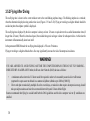
3.3 BEFORE DIVING
NO
A0
A1
A2
3.3.1 Activation, Prechecks and Battery Warning
SURF TIME NO DEC TIME
DIVE
DIVE
CF
TIME
MAX
LOG
HIS
ALT
SET
The instrument is always ready for use and will activate if submerged. However, it is necessary to turn it on before diving to check the personal/ altitude adjustment setting, battery
power, etc. This is done, either by immersing it in water for a couple of seconds or by
connecting the PLAN/ON and COM contacts with fingertips.
PLAN
Fig. 3.3 STARTUP I
All segments shown.
A
S
C
R
A
T
E
a
b
c
m
A
S
C
R
A
T
E
When deactivated the time display is always shown. Once activated all display elements
will turn on (showing mostly figure 8’s and graphical elements) (Fig. 3.3). A few seconds
later the battery power bar graph is shown (Fig. 3.4). Next, the screen will alternate between two READY displays, confirming that the activation is complete (Fig. 3.5). At this
time, perform your precheck making sure that:
m
A
S
C
R
A
T
E
m
A
S
LOG
HIS C ALT SET PLAN
NO
R
A
T
A
E
S
LOG
HIS C ALT SET PLAN
R
A
T
E
LOG
HIS
ALT SET PLAN
d
LOG
HIS
ALT
SET
m
m
• the dive computer operates and provides a complete display
• the low battery indicator is not on
PLAN
e
LOG
HIS
ALT
SET
PLAN
Fig. 3.4 STARTUP II
Battery power indicator. When two or less bar
graph segments are shown the computer
should not be used for diving. (First generation
LUX/LUX S computers: When four or less
bar graph segments are shown the computer
should not be used for diving. For further
information see NOTE on page 24.)
22
• the personal/ altitude adjustment setting is correct
The instrument is now ready for diving. If it is not taken on a dive after activation, it will
automatically switch off to the time display in 10 minutes to conserve the battery power.
The dive computer does not need to be reactivated for repetitive dives. It will remain active
until it has calculated that all residual nitrogen has off-gassed. This may take up to 48
hours, as described in Section 6.1, “Operating Principles”.
PERSONAL ADJUSTMENT AND HIGH ALTITUDE
DIVING
WARNING!
SET THE CORRECT PERSONAL/ALTITUDE ADJUSTMENT MODE! When diving
at altitudes greater than 700 m [2300 ft] the personal/altitude adjustment feature must
be correctly selected in order for the computer to calculate no-decompression status.
The diver should also use this option to make the calculations more conservative, whenever it is believed that factors which tend to increase the possibility of decompression
sickness exist (see Section 3.6). Failure to properly select the personal/altitude adjustment mode correctly will result in erroneous data and can greatly increase the risk of
decompression sickness.
WARNING!
THE DIVE COMPUTER IS NOT INTENDED FOR USE AT ALTITUDES GREATER
THAN 2400 m [8000 ft]! Diving at altitudes above this limit may significantly increase
the risk of decompression sickness.
If you are diving at higher altitudes, make sure that the altitude mode has been set according to the altitude of your dive site.
For information on how to select the correct altitude setting and how to use the personal
adjustment, see Section 3.6, “Personal Adjustment and High Altitude Dives”.
A
S
C
R
A
T
E
m
MAX
A1
SURF TIME
DIVE
TIME
C
LOG
HIS
ALT
SET
PLAN
Fig. 3.5 READY DISPLAYS
The maximum depth and dive time are
zeros (as no dives have yet been made),
the surface interval time is 0 hours 8
minutes (in this case eight minutes after
activation), the temperature is 22°C
[72°F] and the present depth is 0.0 m [0
ft]. The personal/altitude adjustment
mode is A1. The depth display will
alternate between present and maximum
depth. The Low Battery Warning (battery
symbol) indicates that the battery is too
low for diving.
23
BATTERY POWER INDICATOR AND LOW BATTERY WARNING
The instrument has a unique visual Battery Power Indicator designed to give you an advance notice of impending need to change the
battery.
The Battery Power Indicator will always be seen during activation. The following table 3.1 shows the various warning levels (see
also Fig. 3.4).
TABLE 3.1 BATTERY POWER INDICATOR
Display after activation
Operation
Figure
five (5) bar graph segments
normal, new battery
3.3 a) and
3.3 b)
four (4) bar graph segments
three (3) bar graph segments
battery change is recommended
3.3 c)
two (2) bar graph segments
don’t dive, change the battery
3.3 d)
one (1) bar graph segment
don’t dive, after three activations the computer
remains deactivated until the battery has been
replaced
3.3 e)
*) NOTE: First generation LUX/LUX S models made before March 1999 (serial number less than 909001 [first number stands
for year, next two numbers stand for week, last three numbers stand for production number]): Resulting from different battery
control system, when four or less bar graph segments are shown the computer should not be used for diving. Battery change is
recommended.
24
After activation the Low Battery Warning is indicated by the battery symbol. If the battery
symbol is displayed in the surface mode or if the display is faded or weak, the dive computer should not be used (Fig. 3.5). It indicates that the battery is too low to operate the
instrument. If the low battery symbol appears during a dive, you should abort the dive and
begin ascent to the surface.
NOTE: The backlight of the LUX/LUX S models can not be activated, when the low
battery warning is indicated by the battery symbol.
NOTE: Temperature affects the battery voltage. If the dive computer is stored at temperatures below freezing point, the low battery warning may be displayed even though the
battery has enough capacity in warmer conditions. Make sure that the low battery warning disappears before diving.
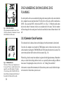
3.3.2 Dive Planning
It is possible at any time on the surface to enter the DIVE PLANNING mode, simply by
touching the PLAN/ON and COM contacts. The display will rapidly cycle through the nodecompression limits for various depths from 9 m [30 ft] to 45 m [150 ft] in 3 m [10 ft]
increments (Fig. 3.6). It takes about 45 seconds to run through the complete cycle, after
which the dive computer will automatically return to the READY display.
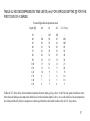
Higher personal/ altitude adjustment modes will shorten the no-decompression time limits.
These limits at different personal/ altitude adjustment mode selections are shown in Tables
6.1 and 6.2 in Section 6.1, “OPERATING PRINCIPLES”.
A
S
C
R
A
T
E
m
A1
NO DEC TIME
DIVE
LOG
HIS
DIVE
TIME
ALT
SET
PLAN
Fig. 3.6 DIVE PLANNING
The no-decompression time limit at 30.0 m
[100 ft] is 14 minutes in A1 mode.
25
A
S
C
R
A
T
E
m
DIVE NUMBERING SHOWN DURING DIVE
PLANNING
A1
NO DEC TIME
DIVE
LOG
HIS
DIVE
TIME
ALT
SET
PLAN
Fig. 3.7 DIVE PLANNING
The no-decompression time limit at 30.0 m
[100 ft] is decreased to 5 minutes in A1 mode
after the third dive of the series.
A
S
C
R
A
T
E
m
Several repetitive dives are considered to belong to the same repetitive dive series when the
dive computer has not deactivated itself. The first dive of the series will be numbered as
DIVE 1, the second as DIVE 2, the third as DIVE 3 etc. (Fig. 3.7). When the surface time
has been less than 10 minutes, the dives are considered to be the same. The dive number
will not change for the second part of such a dive and the dive time will start where it left
off.
3.3.3 Calendar Clock Function
The calendar clock is always shown on the display, when the instrument is deactivated.
Once the dive computer is activated the TIME display can be retrieved any time on the
surface mode by touching the TIME/MODE and COM contacts for about two seconds. The
current time and date will be shown for four seconds (Fig. 3.8).
LOG
HIS
ALT
SET
PLAN
Fig. 3.8 TIME DISPLAY
The time is 10:30 [in case of imperial unit, A
for a.m. and P for p.m. would be shown in the
upper left corner of the display]. The date is
18.2 or February 18th. PLEASE NOTE: The
date will always be displayed with the day of
the month first, followed by the month.
26
When diving, the dive entry time and date is registered in the logbook memory. Remember
always to check before diving that the clock is set, especially when traveling to different
time zones. For adjusting the clock, refer to Sec. 4.4, “Setting Time and Date”.
In the metric version of the instrument, the 24-hour time system is used, while in the imperial version the 12-hour time system is used.
3.4 DIVING
3.4.1 Basic Dive Data
The dive computer will remain in the SURFACE mode at depths less than 1.2 m [4 ft] (first
generation computers 1.8 m [6 ft]). At depths greater than 1.2 m (1.8 m first generation
computers) the instrument will go into the DIVE mode.
Each piece of information on the display is clearly marked (Fig. 3.9). During a no-decompression dive, the following information will be shown:
•
the available no-decompression time (a) in minutes is shown as NO DEC
TIME. It is calculated based on the five factors listed in Section 6.1, “OPERATING PRINCIPLES”.
•
your present depth (d) is shown in meters [ft].
•
the elapsed dive time (f) in minutes in the lower right corner, shown as DIVE
TIME.
•
the personal/ altitude adjustment (e) setting (A0, A1, or A2).
In the lower left corner the following information will alternate:
•
the maximum depth during this dive (b) in meters [ft], indicated as MAX, for
about 5 seconds.
•
the water temperature (c), with °C for Centigrade [or °F for Fahrenheit], for
about 3 second.
A
A
S
C
R
A
T
E
m
d
a
m
aSC
A1
R
A
T
E
e
NO DEC TIME
MAX
DIVE
TIME
b
LOG
HIS
ALT
C
c
LOG
HIS
ALT
SET
f
SET PLAN
DIVE
TIME
PLAN
Fig. 3.9 DIVING DISPLAY
The present depth is 19.3 m [63 ft] (d), the
no-decompression time limit is 23 minutes
(a) in A1 mode (e) and the dive time is 6
minutes (f). Maximum depth during this
dive 29.8 m [98 ft] (b) and water
temperature 18°C [64°F] (c) are alternating
in the lower left corner.
27
A
S
C
R
A
T
E
A
S
C
R
A
T
E
m
3.4.2 Reverse No-Decompression Time Bar Graph
The available no-decompression time is also shown visually in the multi-function bar
graph in the bottom of the display (Fig. 3.10). When your available no-decompression time
decreases below 60 minutes, the first bar graph segment appears. As your body absorbs
more nitrogen, more segments start to appear.
A1
NO DEC TIME
MAX
LOG
DIVE
TIME
HIS
ALT
SET
PLAN
a
Green Zone (a)
b
Fig. 3.10 REVERSE NODECOMPRESSION TIME BAR GRAPH
The first bar from the left appears, when the
available no-decompression time decreases
below 60 minutes. The following bars
appear, when the available nodecompression time decreases below 40, 30,
20 (green zone, a) and 10 minutes (yellow
zone, b).
A
m
S
C
R
A
T
E
As a safety precaution Suunto recommends that divers using the dive computer should
maintain the no-decompression bar graph within the green zone.
Yellow Zone (b)
As all of the bars appear (yellow zone), your no-decompression limit is less than 10 minutes and you are getting very close to no-decompression limits. At this point, you should
start your ascent towards the surface.
A1
NO DEC TIME
MAX
LOG
DIVE
TIME
HIS
ALT
SET
PLAN
Fig. 3.11 ASCENT RATE INDICATOR
Pointer at position two: ascent rate 7 - 9 m/min [23 - 30 ft/min].
28
A
S
C
R
A
T
E
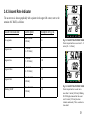
3.4.3 Ascent Rate Indicator
m
MAX
The ascent rate is shown graphically with a pointer in the upper left corner, next to the
notation ASC RATE, as follows:
A1
NO DEC TIME
DIVE
TIME
C
Ascent rate indicator
Ascent speed
Example in Fig. no.
No segments
Below 5 m/min
[16 ft/min]
3.8
Segment one
5 - 7 m/min
[16 - 23 ft/min]
3.9
Segment two
7 - 9 m/min
[23 - 30 ft/min]
3.10
Segment three
9 - 11 m/min
[30 - 36 ft/min]
3.11
Above 11 m/min
[36 ft/min]
3.12
LOG
HIS
ALT
SET
PLAN
Fig. 3.12 ASCENT RATE INDICATOR
Pointer at position three: ascent rate 9 - 11
m/min [30 - 36 ft/min].
A
S
C
R
A
T
E
m
A1
Segment four
Blinking SLOW
Above 10 m/min
[33 ft/min]
NO DEC TIME
MAX
3.12
LOG
DIVE
TIME
HIS
ALT
SET
PLAN
Fig. 3.13 ASCENT RATE INDICATOR
Pointer at position four: ascent rate is
more than 11 m/min [36 ft/min]. Blinking
SLOW displayed means that the ascent
rate 10 m/min [33 ft/min] has been
violated continuously. This is a caution to
slow down!
29
The SLOW warning alternates with the current depth. The SLOW warning is an indication that the maximum ascent rate has been
exceeded continuously, whereas the ascent rate indicator shows present ascent speed.
Whenever the SLOW warning appears, you should immediately slow down or stop your ascent until the warning disappears. You
must not ascend shallower than 3 m [10 ft] with the SLOW warning on. If you reach this depth with SLOW on, you must stop at this
depth and wait until the warning disappears.
WARNING!
RAPID ASCENTS INCREASE THE RISK OF INJURY! Do not exceed the maximum recommended ascent rate.
You must never surface with the SLOW warning on. If you do this, the warning will continue to flash until the unit deactivates itself
in the normal manner. This may take up to 40 hours.
WARNING!
DO NOT ATTEMPT TO DIVE FOLLOWING A SURFACE INTERVAL DURING WHICH THE SLOW INDICATOR REMAINS ACTIVATED! Violation of the maximum ascent rate may invalidate the calculations for the next dive.
NOTE: SUUNTO highly recommends a safety stop at the end of every dive in the range of 3 m - 6 m [10 ft - 20 ft] for 3 - 5
minutes.
30
3.4.4 Alarms
The standard and LUX models feature visual alarms, and the LUX S visual as well as audible alarms, to alert you when you are
approaching dangerous situations.
Potential danger situations during a dive, occurs when:
•
the no-decompression dive turns into a decompression dive. One arrow pointing upwards and the ascend warning
CEILING/ASC TIME will appear (Fig. 3.14). LUX S model gives also an audible alarm: three single beeps.
Immediate danger, happens when:
•
•
the maximum allowed ascent rate, 10 m/min [33 ft/min], is exceeded. A blinking SLOW warning will alternate with the
depth display (Fig. 3.13). LUX S model gives also an audible alarm; continuous beep.
the ceiling depth is exceeded. A downward pointing arrow and a blinking error warning Er will appear (Fig.3.17). LUX
S model gives also an audible alarm: continuous beep. You should immediately descend to or below the ceiling. The
dive computer will otherwise enter a permanent error mode in three minutes, indicated by a non-blinking Er.
•
the ceiling descends to 10 m [30 ft]. A blinking error warning Er appears. You should immediately ascend to or below
the ceiling.
•
the ceiling descends to 12 m [39 ft]. A permanent error warning Er appears. In this mode the instrument can only be
used as a depth gauge and timer.
The permanent ERROR MODE is shown by a non-blinking Er in the center display. Once in ERROR MODE, the dive computer
will continue to display current depth and dive time. You should immediately ascend to a depth of 3 to 6 m [10 to 20 ft] and remain
at this depth until air supply limitations require you to surface. When the surface has been reached, no further diving or flying should
take place for a minimum of two days.
31
A
S
C
R
A
T
E
m
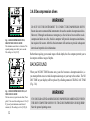
3.4.5 Decompression dives
CEILING
ASC TIME
WARNING!
A1
MAX
LOG
DIVE
TIME
HIS
ALT
SET
PLAN
Fig. 3.14 DECOMPRESSION DIVE,
BELOW THE CEILING ZONE
The minimum ascent time is 4 minutes. The
upward pointing arrow tells you to ascend.
The ceiling is at 3 m [10 ft].
A
S
m
aC
R
A
T
E
c
CEILING
d
A1
MAX
DIVE
TIME
HIS
ALT
SET
BACKGROUND
When your NO DEC TIME becomes zero, your dive becomes a decompression dive, i.e.
you must perform one or several decompression stops on your way to the surface. The NO
DEC TIME on your display will be replaced by a flashing notation CEILING/ ASC TIME
(Fig. 3.14).
PLAN
Fig. 3.15 DECOMPRESSION DIVE, AT
THE CEILING ZONE
The two arrows (a) point at each other ("hour
glass"). You are at the ceiling zone at 3.5 m [11
ft] (c) and your minimum ascent time is 3
minutes (d). The ceiling is at 3 m [10 ft] (b).
32
Rather than requiring you to make stops at fixed depths, the dive computer permits you to
decompress within a range of depths.
ASC TIME
b
LOG
DO NOT USE THIS INSTRUMENT TO CONDUCT DECOMPRESSION DIVES!
Suunto does not recommend this instrument to be used to conduct decompression dives.
However, if through carelessness or emergency a diver is forced to exceed the no-decompression limits on a dive, the dive computer will provide decompression information required for ascent. After this the instrument will continue to provide subsequent
interval and repetitive dive information.
WARNING!
YOU SHOULD ASCEND AND BEGIN DECOMPRESSION IMMEDIATELY WHEN
THE DIVE COMPUTER SHOWS YOU THAT DECOMPRESSION IS REQUIRED!
Note the upward pointing arrow.
The ascent time (ASC TIME) is the minimum amount of minutes needed to reach the surface in a decompression dive. It includes:
The time needed to ascend to the ceiling at an ascent rate of 10 m/min [33 ft/min]
plus
The time needed at the ceiling. The ceiling is the shallowest depth to which you should ascend
plus
The time needed to reach the surface after the ceiling has been removed.
NOTE: Ascent time is not displayed in the Octopus II dive computer (see Figure 3.16).
WARNING!
YOUR ACTUAL ASCENT TIME MAY BE LONGER THAN DISPLAYED ON THE DIVE COMPUTER.
The ascent time will increase if you:
•
remain at depth
•
•
ascend slower than 10 m/min [33 ft/min] or
make your decompression stop deeper than at the ceiling.
These factors will also increase the amount of air required to reach the surface.
WARNING!
NEVER ASCEND ABOVE THE CEILING! You must not ascend above the ceiling. In order to avoid doing so by accident, you
should stay slightly below the ceiling. The ceiling zone is the shallowest depth range to which you should ascend when in
decompression.
33
A
S
m
aC
R
A
T
E
CEILING
c
DISPLAY BELOW CEILING ZONE
d
The CEILING/ASC TIME symbol and upwards pointing arrow indicate that you are below
the ceiling zone (Fig. 3.14). You should start your ascent immediately.
ASC TIME
b
A1
MAX
LOG
DIVE
TIME
HIS
ALT
SET
DISPLAY AT CEILING ZONE
PLAN
Fig 3.16 OCTOPUS II DECOMPRESSION DIVE, AT THE CEILING ZONE
The two arrows (a) point at each other ("hour
glass"). You are at the ceiling zone at 3.5 m
[11 ft] (c) and the ceiling is at 3 m [10 ft] (b).
A
S
C
R
A
T
E
m
CEILING
ASC TIME
A1
When you reach the ceiling zone, the display will show you two arrows pointing toward
each other (the “hour glass” icon, Fig. 3.15). The two arrows pointing toward each other
will be shown between the minimum ceiling and 1.8 m [6 ft] below the minimum ceiling.
All decompression stops must be performed at or below the ceiling depth range.
The depth of the ceiling will depend on your dive profile. It will be fairly shallow when you
enter the decompression mode, but if you remain at depth, it will move downward and the
ascent time will increase.
The ceiling depth will be shown on the left side of the center window.
DIVE
TIME
C
LOG
HIS
ALT
SET
PLAN
Fig. 3.17 DECOMPRESSION DIVE,
ABOVE CEILING
Note the downward pointing arrow and the
blinking Er warning. You should immediately
(within 3 minutes) descend to or below the
ceiling.
34
When the sea surface is rough, it may be difficult to maintain a constant depth near the
surface. In this case it will be more manageable to maintain an additional distance below to
the ceiling, to make sure that the waves do not lift you above the ceiling. SUUNTO recommends that decompression takes place deeper than 4 m [13 ft], even if the indicated ceiling
is shallower.
NOTE: It will take more time and more air to decompress below the ceiling than at
the ceiling.
A
S
C
R
A
T
E
DISPLAY ABOVE CEILING
If you ascend above the ceiling, a downward pointing arrow will appear (Fig 3.17). In
addition a blinking error warning Er reminds you that you have only three minutes to correct the situation. You must immediately descend to or below the ceiling.
WARNING !
NEVER LET THE CEILING DEPTH DESCEND DEEPER THAN 9 m [30 ft]. When
the ceiling is deeper than 9 m [30 ft], a blinking error warning Er will appear and when
the 12 m [39 ft] ceiling is reached the dive computer will go into a permanent error
mode.
NO
b
a
A1
A
S
C
R
A
T
E
m
MAX
DIVE
TIME
C
ASC TIME NO
CEILING
LOG
HIS
ALT SET
PLAN
A1
SURF TIME
DIVE
TIME
C
If you continue to violate the decompression requirements, the dive computer goes into a
permanent ERROR MODE. In this mode (Fig. 3.18) you must not dive again for at least
two days. See also Section 3.7, Error Conditions.
During decompression, ASC TIME will count down toward zero. When the ceiling moves
upwards, you can ascend to the new ceiling. You may surface only when the ascent time
reaches zero and CEILING/ASC TIME is replaced by NO DEC TIME.
m
LOG
HIS
ALT
SET
PLAN
A
S
C
R
A
T
E
m
c
A1
NO DEC TIME
DIVE
LOG
HIS
DIVE
TIME
ALT
SET
PLAN
Fig. 3.18 DISPLAYS AFTER VIOLATED
DECOMPRESSION DIVE
The blinking CEILING/ASC TIME symbol
(a) indicates that you have violated the
ceiling for more than three minutes or the
maximum ceiling depth of 12 m [39 ft] was
exceeded. The instrument will stay as a depth
gauge and timer for 39 hours 59 minutes =
no fly time (b). After 2 hours 30 minutes
surface interval time the no fly time is 37
hours 29 minutes. In the dive planning mode
the Er warning is displayed instead of the nodecompression time (c). You must not dive
again or fly for at least two days.
35
d
A
S
aCR
m
MAX
A
T
E
NO
b
3.5.1 Surface Interval
e
A1
SURF TIME
DIVE
TIME
C
c
LOG
HIS
ALT
SET
An ascent to any depth shallower than 1.2 m [4 ft] (first generation computers 1.8 m [6 ft])
will cause the DIVING display to be replaced by the two SURFACE displays, giving the
following information:
f
PLAN
Fig. 3.19 SURFACE MODE AFTER A
DIVE, DISPLAY I
You have surfaced with the SLOW warning
on (d) 35 minutes ago (b) from a 46 minute
dive (f) that reached a maximum depth of 29.8
m [98 ft] (a). The blinking airplane symbol (e)
indicates that you should not fly. The
temperature is 28°C [82°F] (c).
36
3.5 AT SURFACE
Display I (Fig. 3.19)
•
The surface time in hours and minutes (separated by a colon), telling the
duration of the present surface interval. It is shown above SURF TIME in the
center window of the display (Fig. 3.19, b).
•
The dive time in minutes, i.e. the total duration of the most recent dive, is
displayed next to DIVE TIME in the lower right corner (Fig. 3.19, f).
•
The maximum depth of your most recent dive in meters [ft] is shown in the
same position as your depth readings during the dive. MAX indicator is then
shown in front of the value (Fig. 3.19, a). The SLOW warning will blink over
the maximum depth, if you have surfaced with the SLOW warning on (Fig.
3.19, d).
•
•
The temperature in °C [°F] is shown in the lower left corner (Fig. 3.19, c).
The no-flying warning is indicated by a blinking airplane (Fig. 3.19, e).
Display II (Fig. 3.20)
• The present depth in meters [ft] (Fig. 3.20, a).
• The desaturation/ no-flying time in hours and minutes is shown next to the
A
S
C
R
A
T
E
m
a
NO
non-blinking airplane in the center window of the display (Fig. 3.20, b).
DIVE
TIME
C
If you start a new dive after less than 10 minutes at the surface, the instrument interprets
this as a continuation of the previous dive. The DIVING display will return, the DIVE
number will remain unchanged, and DIVE TIME will begin where it left off. After 10
minutes on the surface, subsequent dives are by definition repetitive. The DIVE counter
displayed in the dive planning mode will progress to the next higher number if you make
another dive after 10 minutes of surface interval time.
b
A1
LOG
HIS
ALT
SET
PLAN
Fig. 3.20 SURFACE MODE AFTER A
DIVE, DISPLAY II
The desaturation time/ no-flying time,
indicated by a non-blinking airplane
symbol, is 11 h 25 min (b). The present
depth is 0.0 m [0 ft] (a).
DIVE PLANNING
You may, at any time on the surface, enter the DIVE PLANNING mode in the manner
described in Section 3.3.2, by touching the PLAN/ON and COM contacts. The dive computer will take into account the residual nitrogen caused by your previous dives. The nodecompression times given for different depths will therefore be shorter than before your
first dive (Fig. 3.7).
You may also read the time by touching the TIME/MODE and COM contacts, as described
in Section 3.3.3 (Fig. 3.8).
37
3.5.2 Flying After Diving
The no-flying time is shown in the center window next to the non-blinking airplane image. The blinking airplane is a reminder,
when the alternative display showing surface time is on (Figures 3.19 and 3.20). Flying or traveling to a higher altitude should be
avoided anytime the airplane symbol is displayed.
The no-flying time displayed by the dive computer is always at least 12 hours or equivalent to the so-called desaturation time (if
longer than 12 hours). When this time has elapsed, the residual nitrogen is no longer a factor for subsequent dives. At this time the
instrument will automatically deactivate itself.
In the permanent ERROR mode the no-flying time displayed is 39 hours 59 minutes.
Flying or traveling to a higher altitude after a dive may significantly increase the risk of decompression sickness.
WARNING!
YOU ARE ADVISED TO AVOID FLYING ANYTIME THE COMPUTER DISPLAYS THE DO NOT FLY WARNING INDICATED BY AN AIRPLANE! Further, the Divers Alert Network (DAN) advises as follows:
•
A minimum surface interval of 12 hours would be required in order to be reasonably assured a diver will remain
symptom free upon ascent to altitude in a commercial jetliner (altitude up to 2400 m [8000 ft]).
•
Divers who plan to make daily, multiple dives for several days, or make dives that require decompression stops, should
take special precautions and wait for an extended interval beyond 12 hours before flight.
Suunto recommends that flying be avoided until both the DAN guidelines and the dive computer wait to fly conditions are
satisfied.
38
3.6 PERSONAL ADJUSTMENT AND HIGH ALTITUDE DIVES
The instrument can be adjusted for increasing the conservatism of the mathematical model or for diving at altitude.
WARNING!
SET THE CORRECT PERSONAL/ALTITUDE ADJUSTMENT MODE! When diving at altitudes greater than 700 m [2300 ft]
the personal/altitude adjustment feature must be correctly selected in order for the computer to calculate no-decompression
status. The diver should also use this option to make the calculations more conservative, whenever it is believed that factors
which tend to increase the possibility of decompression sickness exist. Failure to properly select the personal/ altitude adjustment
mode correctly will result in erroneous data and can greatly increase the risk of decompression sickness.
WARNING!
THE DIVE COMPUTER IS NOT INTENDED FOR USE AT ALTITUDES GREATER THAN 2400 m [8000 ft]! Traveling to a
higher elevation can temporarily cause a change in the equilibrium of dissolved nitrogen in the body with the surroundings. It is
recommended that the diver allow the body conditions to stabilize over a period of at least three hours before beginning to dive
at altitude.
39
ALTITUDE ADJUSTABILITY
When programming the instrument for the correct altitude, the diver needs to select the correct altitude mode according to Table 3.2.
As a result the dive computer adjusts its mathematical model according to the entered altitude, giving shorter no-decompression
times at higher altitudes (Tables 6.1 and 6.2).
The entered personal/altitude adjustment mode is indicated by A0, A1, or A2. Section 4.3, Personal/Altitude Adjustment Setting
describes how the altitude mode is adjusted.
Table 3.2 ALTITUDE RANGES
Altitude mode
Altitude range
A0
A1
A2
0 - 700 m
700 - 1500 m
1500 - 2400 m
[0 - 2300 ft]
[2300 - 5000 ft]
[5000 - 8000 ft]
PERSONAL ADJUSTABILITY
The factors, which tend to increase the possibility of decompression sickness, include but are not limited to:
•
cold exposure - water temperature less than 20°C [68°F]
•
the diver is below average physical fitness level
•
multiday or repetitive dive exposure
•
diver fatigue
•
dehydrated conditions
•
previous history of decompression sickness
40
This feature should be used to adjust the computer to intentionally introduce a factor to make it more conservative according to
personal preference by entering a higher altitude mode than required in table 3.2 (i.e. diving at sea level with the personal/ altitude
adjustment set at A1 or A2). The no-decompression limits are then shortened accordingly (Tables 6.1 and 6.2).
WARNING!
DO NOT USE THIS INSTRUMENT TO CONDUCT DECOMPRESSION DIVES! Suunto does not recommend this instrument
to be used to conduct decompression dives. However, if through carelessness or emergency a diver is forced to exceed the nodecompression limits on a dive, the instrument will provide decompression information required for ascent. After this the dive
computer will continue to provide subsequent interval and repetitive dive information.
3.7 ERROR CONDITIONS
The instrument is provided with warning indicators that advise the user to react to certain situations that would otherwise give rise
to a significantly increased risk of decompression sickness if left unattended. If you do not respond to its warnings, it will enter a
permanent ERROR MODE, indicating that the risk of decompression sickness has greatly increased. If you understand and operate
the dive computer sensibly, it is unlikely that you will ever put the instrument into the ERROR MODE.
The permanent ERROR MODE is shown by a non-blinking Er in the center display. Once in ERROR MODE, the dive computer
will continue to display current depth and dive time. You should immediately ascend to a depth of 3 to 6 m [10 to 20 ft] and remain
at this depth until air supply limitations require you to surface. When the surface has been reached, no further diving or flying should
take place for a minimum of two days.
41
OMITTED DECOMPRESSION
The most common ERROR MODE results from omitted decompression, when the diver stays above the ceiling for more than three
minutes. During this three-minute period the Er warning will blink alternating with the CEILING/ASC TIME display. The instrument will continue to function normally, if the diver descends below the ceiling within three minutes.
After this the dive computer will enter a permanent ERROR MODE. In the permanent ERROR MODE the instrument will not show
no-decompression or ascent times. Only a permanent Er warning is shown in the center window. However, all the other displays will
function as before, to provide information for ascent.
At the surface mode, the CEILING/ASC TIME symbol will blink in the center window and at the dive planning mode a permanent
Er is shown instead of no-decompression times.
EXTREME CEILING DEPTH OR DECOMPRESSION RANGE
When the ceiling descends to the depth of 10 m [30 ft] or when the ASCent TIME is longer than 63 minutes, the Er warning will
start to blink in the center window. If the diver immediately ascends, the dive computer will continue to function normally after the
ceiling is back to below 10 m [30 ft] or the ASCent TIME is shorter than 63 minutes.
If the ceiling descends to the depth of 12 m [39 ft] even momentarily the instrument will enter the permanent ERROR MODE.
NOTE: Ascent time is not displayed in the Octopus II dive computer.
42
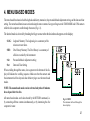
4. MENU BASED MODES
The menu based functions include the logbook and history memories, the personal/altitude adjustment setting, and the date and time
setting. The menu based functions are activated using the water contacts. Keep your fingers on the TIME/MODE and COM contacts
while the dive computer scrolls through the menu (Fig. 4.1).
The desired mode is selected by breaking the finger contact when the desired mode appears on the display:
•LOG:
Logbook Memory. The Logbook gives a summary of the
nine most recent dives.
•HIS:
•Alt:
Dive History Memory. The Dive History is a summary of
all dives recorded by the instrument.
Personal/Altitude Adjustment setting
•Set:
Date and Time Setting
When scrolling through the menu, a bar segment on the bottom of the display will indicate the scrolling sequence. Make sure that the contacts and
the instrument itself are dry and clean before trying to use the menu based
modes.
NOTE: The menu based modes can be activated only when 10 minutes
have elapsed after the dive.
All menu based modes can be deactivated by the RETURN command, i.e.
by connecting all three contacts simultaneously, or by immersing the dive
computer in water.
A
S
C
R
A
T
E
m
A
S
C
R
A
T
E
LOG
HIS
m
ALT
LOG
A
S
C
R
A
T
E
SET PLAN
HIS
ALT
m
A
S
C
R
A
T
E
SET
LOG
m
PLAN
HIS
ALT
SET
PLAN
LOG
HIS
ALT
SET
PLAN
Fig. 4.1 MENU
The instrument will scroll through the
above displays.
43
A
S
aCR
m
MAX
A
T
E
b
A1
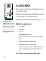
4.1 LOGBOOK MEMORY
d
The dive computer has a sophisticated high capacity Logbook Memory. Dives shorter
than one minute are not registered.
e
The logbook memory is activated by touching the TIME/MODE and COM contacts until
LOG appears. It will give access to the nine most recent dives made.
NO DEC TIME
DIVE
DIVE
TIME
c
LOG
HIS
ALT
SET
PLAN
Fig 4.2 LOGBOOK, DISPLAY I
This display will alternate between DISPLAYS
II and III. The maximum depth (a) of the second
recent dive (c) was 28.6 m [94 ft] and the total
dive time 29 min (e). The personal/altitude
adjustment mode was set to A1 (d) and the
minimum no-decompression time during the
dive was 3 minutes (b).
The following information will be shown on three alternating displays (Fig. 4.2 - 4.5):
DISPLAY I, main display (Fig. 4.2):
•
maximum depth (a)
•
•
dive number (c)
dive time (e)
•
personal/altitude adjustment setting (d)
•
•
the minimum NO DEC TIME or maximum ASC TIME reached during the
dive (b)
SLOW if the diver has surfaced with this warning on
•
downward pointing arrow if the ceiling was violated
•
Er in the center window, if the ceiling was violated permanently (over 3 min)
or if the 12 m [39 ft] ceiling was reached or if the ASC TIME was over 63
min.
NOTE: Ascent time is not displayed in the Octopus II dive computer.
44
DISPLAY II (Fig. 4.3):
•
average depth (a)
•
•
surface interval time before dive (b)
temperature at the maximum depth (c)
•
dive time
A
S
C
R
A
T
E
a
m
b
SURF TIME
LOG
DISPLAY III (Fig. 4.4):
•
dive entry time and date
The data of the most recent dive is shown first as DIVE 1 (the first dive in the memory).
Preceding dives are recalled by touching the TIME/MODE and COM contacts. A brief
touch of the contact will bring you to the previous dive (DIVE 2), continuous contact
scrolls backwards through the dives (DIVE 3, ... DIVE 9, DIVE 1 again etc.). Only DISPLAY I is shown, while scrolling the dives. The desired dive is selected by breaking the
contact when that dive appears on the display.
When new dives are added after nine dives, the oldest dives are deleted. The memory will
always retain the nine most recent dives. The contents of the memory will remain even
when the battery is changed (assuming that the replacement has been done according to the
instructions).
DIVE
TIME
C
c
HIS
ALT
SET
PLAN
Fig 4.3 LOGBOOK, DISPLAY II
The average depth of the dive was 18.2 m
[60 ft] (a), surface interval time before the
dive 10 h 38 min (b) and temperature at
the maximum depth 20°C [68°F] (c).
A
S
C
R
A
T
E
m
LOG
HIS
ALT
SET
PLAN
Fig 4.4 LOGBOOK, DISPLAY III
The dive started on the 18th of August
(8) at 8:26 [when set to imperial version,
A for a.m or P for p.m. are also shown in
the upper left corner of the display].
45
NOTE: The dive numbers shown in the dive planning mode do not match the ones
shown in the logbook.
a
bAS
C
R
A
cTE
m
MAX
CEILING
ASC TIME
A1
NO
DIVE
LOG
HIS
d
DIVE
TIME
ALT
SET
PLAN
Fig 4.5 VIOLATION DISPLAYS IN
THE LOGBOOK, DISPLAY I
Display I shows SLOW warning (a) for
surfacing with the SLOW warning on, a
downward pointing arrow for a violated
ceiling (b), CEILING/ ASC TIME
symbol (c) for decompression dive. Er
in the ASC TIME display (d) is shown,
if the ceiling was violated over 3 min, or
if the ceiling depth was over 12 m [39
ft] or if the ascent time was over 63
min.
46
In the dive planning mode the dives are numbered according subsequent repetitive dives
within a dive series, whereas in the logbook the dives are numbered according memory
address.
NOTE: The logbook contains test dives made in the factory. These dives will be deleted after you have performed nine dives.
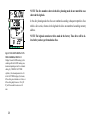
4.2 DIVE HISTORY MEMORY
The Dive History is activated by touching the TIME/MODE and COM contacts until
HIS appears. This mode will show (Fig. 4.6):
A
S
aCR
m
MAX
A
T
E
• the maximum depth ever reached (a)
• the total number of dives (b)
• the total accumulated dive time in hours (c)
c
DIVE
b
LOG
999 dives and 999 hours of diving can be registered. When these maximum values
are reached, the counters will start again from 0.
NOTE: The maximum depth will be zeroed, if the depth of 97.6 m [320 ft] is exceeded.
DIVE
TIME
HIS
ALT
SET
PLAN
Fig. 4.6 DIVE HISTORY
The maximum depth ever reached is 33.0 m
[108 ft] (a), the total accumulated dive time
29 hours (c), and the total number of dives
36 (b).
NOTE: The dive and dive time counters in the History Memory contain some test
dives made in the factory (e.g. DIVE 2, DIVE TIME 1 h). The maximum depth is,
however, zeroed.
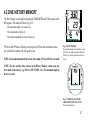
A
S
C
R
A
T
E
m
A1
TIME
MODE
PLAN
ON
COM
LOG
HIS
ALT
SET
PLAN
Fig. 4.7 PERSONAL/ALTITUDE
ADJUSTMENT SETTING, STEP 1
The current mode is A1.
47
A
S
C
R
A
T
E
4.3 PERSONAL/ALTITUDE ADJUSTMENT
SETTING
m
A0
A1
A2
TIME
MODE
PLAN
ON
COM
LOG
HIS
ALT
SET
PLAN
Fig. 4.8 PERSONAL/ALTITUDE
ADJUSTMENT SETTING, STEP 2
The current mode A1 is blinking. Lift your
fingers.
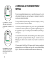
A
S
C
R
A
T
E
m
A0
A1
A2
TIME
MODE
PLAN
ON
COM
LOG
HIS
ALT
SET
PLAN
Fig. 4.9 PERSONAL/ALTITUDE
ADJUSTMENT SETTING, STEP 3
Release your fingers when the desired
mode is blinking.
48
The current personal/altitude adjustment mode is shown when diving as well as on the
surface display. If the mode is not correct (see Chapter 3.6), it is imperative that the diver
enter the correct selection before diving.
The new personal/altitude adjustment setting is entered in the following way. In these figures the contacts which are connected are shadowed.
1. Activate the personal/altitude adjustment setting mode by connecting the TIME/MODE
and COM contacts continuously. Release your fingers immediately when Alt appears on
the display. Within a couple of seconds the present personal/altitude adjustment setting is
shown (Fig. 4.7).
2. Connect the PLAN/ON and COM contacts until all three personal/ altitude adjustment
modes appear. Release your fingers immediately at this point. The current mode is now
blinking (Fig. 4.8). Wait at least two seconds but not more than four seconds before the
next step.
3. Connect again the PLAN/ON and COM contacts until the blinking personal/altitude
adjustment mode starts to scroll. Release your fingers when the desired mode is blinking
(Fig. 4.9). Wait at least two seconds but no more than four seconds before next step.
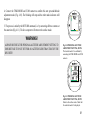
4. Connect the TIME/MODE and COM contacts to confirm this new personal/altitude
adjustment mode (Fig. 4.10). The blinking will stop and the other mode indicators will
disappear.
A
S
C
R
A
T
E
m
TIME
MODE
A2
5. The process is ended by the RETURN command, i.e. by connecting all three contacts at
the same time (Fig. 4.11). The dive computer will return to the surface mode.
PLAN
ON
COM
LOG
HIS
ALT
SET
PLAN
WARNING!
ALWAYS RECHECK THE PERSONAL/ALTITUDE ADJUSTMENT SETTING TO
ENSURE THAT IT IS NOT SET FOR AN ALTITUDE LESS THAN THAT OF THE
DIVE SITE!
Fig. 4.10 PERSONAL/ALTITUDE
ADJUSTMENT SETTING, STEP 4
The desired mode A2 is confirmed by
connecting the TIME/MODE and COM
contacts.
A
S
C
R
A
T
E
m
MAX
A2
SURF TIME
DIVE
TIME
C
COM
LOG
HIS
ALT
SET
TIME
MODE
PLAN
ON
PLAN
Fig. 4.11 PERSONAL/ALTITUDE
ADJUSTMENT SETTING, STEP 5
Return to the surface mode. Check that
the selected mode A2 is displayed.
49
49
4.4 SETTING TIME AND DATE
A
S
C
R
A
T
E
m
CHANGE
DISPLAY
TIME
MODE
PLAN
ON
COM
LOG
HIS
ALT
SET
PLAN
CHANGE
VALUE
The current date and time is read by connecting the TIME/MODE and COM contacts for
about two second, as described in Section 3.3.3, “Calendar Clock Function”.
Once the Time Setting mode is activated the principle when adjusting the clock is that:
•
Fig. 4.12 TIME SETTING
Ready to adjust the hour reading (blinking).
the TIME/MODE and COM contacts scroll through the different displays,
•
the PLAN/ON and COM contacts change the values of the selected display.
In these figures the contacts which are connected are shadowed.
Thus, to correct the time, do as follows:
A
S
C
R
A
T
E
1. Activate the Time Setting mode by connecting the TIME/MODE and COM contacts
continuously to scroll through the menu. Release your fingers immediately when Set appears on the display. The Time Setting display will now be shown (Fig. 4.12).
m
TIME
MODE
PLAN
ON
COM
LOG
HIS
ALT
SET
PLAN
Fig. 4.13 TIME SETTING
Adjusting the hour reading, PLAN/ON & COM.
50
2. The hour display starts to blink immediately (Fig. 4.12). If you want to change it, keep
the PLAN/ON and COM contacts connected. The hours will start to scroll (Fig. 4.13).
Release your fingers immediately when the correct value is displayed. [To change the A or
P for a.m. or p.m. scroll the hours past 12:00].
3. To scroll through the minute, month and date, keep the TIME/MODE and COM contacts
connected. Release your fingers when the display you wish to change is blinking (Fig.
4.14). Repeat step 2 to change this value (Fig. 4.15).
NOTE: In case of the minutes and date, the change is made separately for both digits,
as shown by the blinking digit. In case of the hours and month, the complete number
is changed simultaneously.
4. Repeat steps 2 and 3 to change any additional values.
A
S
C
R
A
T
E
m
TIME
MODE
PLAN
ON
COM
LOG
5. Exit the Time Setting mode with the RETURN command, i.e. by connecting all three
HIS
ALT
SET
PLAN
contacts at the same time. First make contact between the PLAN/ON and TIME/MODE
contacts and after that with the COM contact.
NOTE: The clock is on (time is elapsing) when setting it and exiting the Time Setting
mode. It is not possible to reset the seconds.
Fig. 4.14 TIME SETTING
Scrolling through hours, minutes, month
and date, TIME/MODE & COM.
Remember to regularly check that the clock is on time especially when traveling to different time zones, as the entry time of all dives is stored in the logbook memory.
A
S
C
R
A
T
E
m
TIME
MODE
PLAN
ON
COM
LOG
HIS
ALT
SET
PLAN
Fig. 4.15 TIME SETTING
Adjusting the ten minute reading (blinking),
PLAN/ON & COM.
51
5. CARE AND MAINTENANCE
The dive computer is a sophisticated precision instrument. Remember to treat it as such! It has been designed to withstand the rigors
of scuba diving. It can be installed in a durable thermoplastic console boot and its display can be protected by a replaceable display
shield.
The user should wash and rinse the unit in fresh water after every use. Protect it from shocks, extreme heat or direct sunlight and
chemical attack. The instrument cannot withstand the impact of heavy objects like scuba cylinders, nor chemicals like acetone and
alcohols (ethanol, isopropanol).
NOTE: Keep the water contacts clean to assure correct operation of the dive computer. Store the instrument in a dry place.
NOTE: Frequently check the battery compartment for moisture through the transparent battery cover of the instrument
especially after the battery replacement.
The dive computer should be serviced every two years or after 300 dives (whichever comes first) by an authorized dealer. This
service will include a general operational check and battery replacement. The service requires special tools and training. Therefore,
it is advisable to contact an authorized Suunto dealer for biennial service. Do not attempt to do any servicing that you are not trained
for.
The instrument will display a battery symbol as a warning when the power gets too low. When this happens, the dive computer
should not be used until the battery has been replaced (see also chapter 3.3.1 /Battery Warning).
52
5.1 MAINTENANCE
If left without care for an extended period, a thin film (often invisible to the eye) will cover the unit. Much like the buildup on the
glass of an aquarium, this film is the result of organic contaminates found in both salt and fresh water. Suntan oil, silicone spray and
grease will speed up this process. As a result of this buildup, moisture will be trapped next to the contacts and will not allow your
dive computer to operate properly.
The water contacts can be cleaned with a soft pencil eraser.
IMPORTANT: The instrument should be soaked, then thoroughly rinsed with fresh water after each dive.
If the unit is mounted in a console boot, the entire console should be soaked in fresh water and then rinsed. Make sure that all salt
crystals and sand particles have been flushed out of the console.
At the end of a dive trip, the dive computer should be rinsed thoroughly and then dried with a soft towel. If the unit is mounted into
a console boot, the computer unit will need to be removed from the console and cleaned before storage.
IMPORTANT: When removing the computer from the console, check the battery compartment for possible moisture or water. This
is easily done through the transparent lid covering the compartment. DO NOT use the instrument if you detect any moisture or water
inside.
53
CAUTION!
Do not use compressed air to blow water off the unit
Do not use solvents or other cleaning fluids that might cause damage
Do not test or use the dive computer in pressurized air.
5.2 BATTERY COMPARTMENT INSPECTION
Frequently check for leaks in the battery compartment. This is important especially after the battery has been replaced. If you find
moisture inside the transparent battery compartment lid, there is a leak.
A leak must be corrected without delay, as moisture will seriously damage the computer, even beyond repair. Suunto does not take
any responsibility for damage caused by moisture in the battery compartment, if the instructions of this manual are not carefully
followed.
In case of a leak immediately bring the instrument to an authorized Suunto dealer/distributor.
54
6. TECHNICAL DESCRIPTION
6.1 OPERATING PRINCIPLES
The Suunto dive computer is a multi-functional sport diving instrument, which provides information on depths, times and decompression requirements. Its electronic microprocessor mathematically models the absorption and release of nitrogen during all phases
of diving, including ascents, surface intervals and repetitive dives.
WARNING!
DO NOT ATTEMPT TO USE THE INSTRUMENT WITHOUT FIRST READING THE ENTIRE OWNER’S MANUAL! The
dive computer must be activated before diving and operated correctly to provide accurate and correct information.
NO-DECOMPRESSION LIMITS
The no-decompression limits displayed by the dive computer upon activation are for most dives to a single depth slightly more
conservative than those permitted by the U.S. Navy tables, Tables 6.1-6.2.
55
TABLE 6.1 NO-DECOMPRESSION TIME LIMITS (min) FOR VARIOUS DEPTHS [m] FOR
THE FIRST DIVE OF A SERIES.
Personal/high altitude adjustment mode
56
Depth [m]
A0
A1
A2
9
12
15
18
21
24
27
30
33
36
39
42
45
125
71
52
37
29
22
18
13
11
9
7
6
153
89
57
39
29
24
18
14
11
9
7
6
5
104
66
42
30
23
19
15
12
9
8
6
5
5
TABLE 6.2 NO-DECOMPRESSION TIME LIMITS (min) FOR VARIOUS DEPTHS [ft] FOR THE
FIRST DIVE OF A SERIES.
Personal/high altitude adjustment mode
Depth [ft]
A0
A1
A2
U.S. Navy
30
40
50
60
70
80
90
100
110
120
130
140
150
120
69
51
36
28
22
17
13
10
9
7
6
149
86
56
38
29
23
18
14
11
9
7
6
5
102
65
41
29
23
19
15
11
9
8
6
5
4
200
100
60
50
40
30
25
20
15
10
10
5
Unlike the U.S. Navy tables, the instrument interpolates between depths, giving a diver “credit” for time spent in shallower water,
rather than calculating no-decompression limits based on the maximum depth of a dive. As a result, multi-level no-decompression
dive times permitted by the dive computer are often longer than those that would be allowed by the U.S. Navy tables.
57
WARNING!
THE USER SHOULD BE AWARE THAT ANY DIVE, INCLUDING ONES WITHIN THE U.S. NAVY TABLES OR DIVE
COMPUTER LIMITS, DOES CARRY SOME RISK OF DECOMPRESSION SICKNESS.
COMPARTMENTS AND HALF TIMES
When you dive with the instrument, it measures and displays depths and times as your dive progresses. It shows you available nodecompression time and possible decompression required based upon the following five factors:
1. your present depth,
2. excess nitrogen absorbed during earlier portions of the dive,
3. residual nitrogen remaining from previous dives,
4. the no-decompression limits that apply to that depth,
5. the personal/altitude adjustment mode in use.
Back on the surface, the dive computer will continue to calculate the no-decompression dive times available for various depths on
the next dive. As the surface interval increases, so does the available dive time for the next dive.
To perform these calculations, the dive computer continuously models the absorption and release of excess nitrogen from theoretical compartments. Each compartment absorbs and releases nitrogen at a different rate. The compartments that absorb and release
nitrogen rapidly are believed to have a high tolerance for excess nitrogen, whereas compartments that absorb and release nitrogen
more slowly are believed to be more sensitive.
58
The no-decompression limits in the U.S. Navy tables are based upon six theoretical compartments for single dives, and one compartment for surface intervals and repetitive dives. If you are familiar with table theory, you may know that they are characterized by
half times (i.e. the time required for 50 % equilibration to a pressure change) ranging from 5 minutes to 120 minutes.
The instrument includes the same six compartments, and two additional compartments for an increased range of the mathematical
model. The calculations are based on all eight compartments for all phases of diving, including surface intervals and repetitive
dives. The dive computer’s half times range from 2.5 to 320 minutes. The multi-level tissue calculations are based on modified
Haldanean principle.
ALTITUDE DIVING
The atmospheric pressure is lower at high altitudes than at sea level. After traveling to a higher altitude, the diver will have additional nitrogen in his body, compared to the equilibrium situation at the original altitude. This “additional” nitrogen is released
gradually in time and equilibrium is reached within a couple of days.
Before high altitude diving the instrument must be set to high altitude diving mode to take this into account. The maximum partial
pressures of nitrogen allowed by the mathematical model of the dive computer are reduced according to the lower ambient pressure.
As a result the allowed no-decompression limits are considerably reduced.
59
SURFACE INTERVALS
The dive computer requires a minimum surface interval of 10 minutes between dives. If a surface interval is shorter than 10 minutes,
the instrument dive counter and dive timer treat the next dive as a continuation of the previous dive. It adds the dive times, and
calculates no-decompression limits or decompression stops based on excess nitrogen absorbed on both dives. In this regard, it is
similar to the U.S. Navy tables.
DEPTH LIMITS
WARNING!
SUUNTO STRONGLY RECOMMENDS THAT SPORT DIVERS LIMIT THEIR MAXIMUM DEPTH TO 40 m [130 ft]!
However, the dive computer will calculate below that depth to provide a wide margin of flexibility if, through carelessness or
emergency, you are forced to exceed this recommended depth limit for a dive.
60
6.2 TECHNICAL SPECIFICATION
DIMENSIONS AND WEIGHT (WRIST MODEL):
•
•
•
Diameter: 61.5 mm [2.42 in]
Depth:
29 mm [1.14 in]
Weight:
105 g [0.23 lb]
DEPTH GAUGE:
•
•
•
•
•
Temperature compensated pressure sensor
Salt water calibrated (in fresh water the readings are about 3% smaller)
Depth display range: 0 to 90 m [295 ft]
Accuracy:
± 1 % FS (0 to 60 m [200 ft] at 20°C [68°F])
Resolution:
0.1 m [1 ft]
TEMPERATURE DISPLAY:
•
•
•
Resolution: 1 °C [1.5°F]
Display range: - 20 ... +50°C [- 40 ... +122°F]
Accuracy:
± 2 °C [± 3.6°F] within 20 minutes of temperature change
CALENDAR CLOCK:
•
•
•
Accuracy: ± 2.5 s /24 h
24 h clock display [12 h display in imperial version]
day and month
61
OTHER DISPLAYS:
•
•
•
•
•
•
Dive time:
Surface time:
Dive counter:
No-decompression time:
Ascent time:
puter.
Ceiling range:
0 to 199 min (999 dive hours in the history memory)
0 to 39 h 59 min
0 to 255 dives (999 dives in the history memory)
0 to 199 min (- - after 199)
0 to 63 min (- -/Er after 63) NOTE: Ascent time is not displayed in Octopus II dive com3 to 9 m [10 to 30 ft]: blinking Er (ERROR) from 10 to 12 m [30 to 39 ft], after that
permanent Er (ERROR) mode
OPERATING CONDITIONS
•
•
•
Normal altitude range: 0 to 2400 m [8000 ft] above sea level
Operating temperature: 0 to 40°C [32°F to 104°F]
Storage temperature: -20°C to +50°C [-4°F to +122°F]
It is, however, recommended that the unit be stored in a dry place at room temperature.
NOTE: Do not leave the instrument in direct sunlight!
BATTERY
LUX/LUX S MODELS
• One 3.0 V lithium battery (Varta CR 1/2 AA ), size 1/2
AA (ANSI) or 1/2 R6 (IEC), spare part number K5546 +
O-ring 26.7 mm x 1.78 mm 70 ShA, spare part number
62
K5508
• Battery life: typically more than 3000 hours (at 20°C [68°F])
• One 3.6 V lithium battery, size 1/2 AA (ANSI) or 1/2 R6
(IEC), spare part number K5504 + O-ring 26.7 mm x 1.78 mm
70 ShA, spare part number K5508
• Battery life: typically more than 2500 hours (at 20°C [68°F]).
The use of the backlight shortens the typical expected battery
life.
7. WARRANTY
NOTE: The warranty arrangements are different in different countries. Information is contained in the dive computer
packaging regarding the warranty benefits and requirements applicable to your purchase.
The Suunto dive computer is warranted against defects in workmanship and materials for a period of two years after purchase to the
original owner subject to and in accordance with the terms and conditions set forth below:
This warranty does not cover damage to the product resulting from improper usage, improper maintenance, neglect of care, alteration or unauthorized repair. This warranty will automatically become void if proper preventive maintenance procedures have not
been followed as outlined in the use and care instructions for this product.
If a claim under this or any other warranty appears to be necessary, return the product, freight prepaid, to your Suunto Dealer or
qualified repair facility. Include your name and address, proof of purchase and/or service registration card, as required in your
country. The claim will be honored and the product repaired or replaced at no charge and returned in what your Suunto Dealer
determines a reasonable amount of time, provided all necessary parts are in stock. All repairs made, not covered under the terms of
this warranty, will be made at the owner’s expense. This warranty is non-transferable from the original owner.
All implied warranties, including but not limited to the implied warranties of merchantability and fitness for a particular purpose,
are limited from date of purchase and in scope to the warranties expressed herein. Suunto shall not be liable for loss of use of the
product or other incidental or consequential costs, expenses or damage incurred by the purchase. All warranties not stated herein are
expressly disclaimed.
Some states do not allow the exclusion or limitation of implied warranties of consequential damages, so the above exclusions or
limitations may not apply to you. This warranty gives you specific legal rights, and you may also have other rights that vary from
state to state.
This warranty does not cover any representation or warranty made by dealers or representatives beyond the provisions of this
warranty. No dealer or representation is authorized to make any modifications to this warranty or to make any additional
warranty. Battery replacement is not covered by this warranty.
This Instruction Manual should be kept with your dive computer.
63
8. GLOSSARY
Altitude dive
A dive made at an elevation above 700 m [2300 ft] above sea-level.
Ascent rate
The speed at which the diver ascends toward the surface.
ASC RATE
Abbreviation for ascent rate.
Ascent time
The minimum amount of time needed to reach the surface in a decompression dive.
ASC TIME
Abbreviation for ascent time.
Ceiling
On a decompression dive the shallowest depth to which a diver may ascend based on computer
nitrogen load.
Ceiling Zone
On a decompression dive the zone between the ceiling and the ceiling plus 1.8 m [6 ft]. This depth
range is displayed with the two arrows pointing toward each other (the “hourglass” icon).
Compartment
See “Tissue group”.
DCS
Abbreviation for decompression sickness.
Decompression
Time spent at a decompression stop or range before surfacing, to allow absorbed nitrogen to
escape naturally from tissues.
Decompression sickness
Any of a variety of maladies resulting either primarily or secondary from the formation of nitrogen
bubbles in tissues or body fluids, as a result of inadequately controlled decompression. Commonly
called “bends” or “DCS”.
Dive series
A group of repetitive dives between which the instrument indicates some nitrogen loading is
present. When nitrogen loading reaches zero the instrument deactivates.
64
Dive time
Elapsed time between leaving the surface to descend, and returning to the surface at the end of a
dive.
Half-time
After a change in ambient pressure, the amount of time required for the partial pressure of nitrogen
in a theoretical compartment to go half-way from its previous value to saturation at the new ambient
pressure.
Multi-level dive
A single or repetitive dive that includes time spent at various depths and whose no-decompression
limits are not determined solely by the maximum depth attained.
No-decompression time
The maximum amount of time a diver may remain at a particular depth without having to make
decompression stops or remain below a ceiling during the subsequent ascent.
No-decompression dive
Any dive which permits a direct, uninterrupted ascent to the surface at any time.
NO DEC TIME
Abbreviation for no-decompression time limit.
Repetitive dive
Any dive whose no-decompression time limits are affected by residual nitrogen absorbed during
previous dives.
Residual nitrogen
The amount of excess nitrogen remaining in a diver after one or more dives.
SURF TIME
Abbreviation for surface interval time.
Surface interval time
Elapsed time between surfacing from a dive and beginning a descent for the subsequent repetitive
dive.
Tissue group
Theoretical concept used to model bodily tissues for the construction of decompression tables or
calculations.
65
66