1
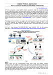
ZB-2570/ZB-2571 Series
User Manual
ICP DAS, ZB-2570/ZB-2571 Series User Manual, Ver2.0
Page
1
Warranty
All products manufactured by ICP DAS are warranted against defective
materials for a period of one year from the date of delivery to the original purchaser.
Warning
ICP DAS assumes no liability for damages consequent to the use of this
product. ICP DAS reserves the right to change this manual at any time without
notice. The information furnished by ICP DAS is believed to be accurate and
reliable. However, no responsibility is assumed by ICP DAS for its use, or for any
infringements of patents or other rights of third parties resulting from its use.
Copyright
Copyright 2009 by ICP DAS. All rights are reserved.
Trademark
The names used in this manual are for identification purposes only and may be
registered trademarks of their respective companies.
ICP DAS, ZB-2570/ZB-2571 Series User Manual, Ver2.0
Page
2
Table of Contents
1.
2.
3.
4.
5.
6.
7.
8.
Introduction .......................................................................................................... 4
Specifications ........................................................................................................ 5
Product Description ............................................................................................... 7
3.1. Internal I/O Structure .................................................................................. 7
3.2. Appearance ................................................................................................. 9
3.3. Dimensions (Units: mm) ............................................................................ 10
Applications......................................................................................................... 11
4.1. Operating Modes ....................................................................................... 11
4.2. Application Mode Introduction .................................................................... 12
4.2.1. Serial Transparent Mode: ............................................................ 12
4.2.2. Modbus RTU/ASCII Mode:........................................................... 13
4.2.3. Serial Addressable Mode: ............................................................ 14
4.2.4. Serial ZBIO Mode: ...................................................................... 15
4.2.5. Ethernet Transparent Mode:........................................................ 16
4.2.6. Modbus TCP Mode:..................................................................... 17
4.2.7. Ethernet Addressable Mode: ...................................................... 18
4.2.8. Ethernet ZBIO Mode:................................................................. 19
4.2.9. Modbus RTU/ASCII to Modbus TCP Mode: ................................... 20
4.2.10. Modbus TCP to Modbus RTU/ASCII Mode:.................................. 21
4.2.11. Virtual COM Transparent Mode: ................................................. 22
Quick Start for the ZB-2570 and ZB-2571 series module ...................................... 23
5.1. Installing the Configuration Tool ................................................................. 23
5.2. ZB-2570 and ZB-2571 series Hardware Configuration .................................. 25
5.3. Quick Start for the ZigBee Converter........................................................... 27
5.3.1. Setup Wizard: ........................................................................... 29
5.3.2. Quick Setting: ........................................................................... 31
5.3.3. Default ..................................................................................... 34
5.3.4. Configuration Message .............................................................. 35
5.4. Examples of Configuring the Operating Mode .............................................. 37
1. Serial Port Operating Mode – Transparent Mode: .................................. 37
2. Serial Port Operating Mode – Modbus RTU/ASCII Mode:........................ 38
3. Serial Port Operating Mode – Addressable Mode: .................................. 39
4. Serial Port Operating Mode – ZBIO Mode: ............................................ 40
5. Ethernet Operating Mode – Transparent Mode: ..................................... 41
6. Ethernet Operating Mode – Modbus TCP Mode: .................................... 42
7. Ethernet Operating Mode – Addressable Mode:..................................... 43
8. Ethernet Operating Mode – ZBIO Mode: ............................................... 44
9. Multi-Interface Mode – Modbus RTU to Modbus TCP Mode: ................... 45
10. Multi-Interface Mode – Modbus TCP to Modbus RTU Mode:.............. 46
11. Virtual COM Mode.......................................................................... 48
5.5. Installing the Hardware.............................................................................. 49
5.6. Confirm the Transmission:.......................................................................... 52
Appendix............................................................................................................. 53
Ordering Information ........................................................................................... 55
Accessories ......................................................................................................... 56
ICP DAS, ZB-2570/ZB-2571 Series User Manual, Ver2.0
Page
3
1. Introduction
ZigBee Network
The ZB-2570/2570P/2570-T/2570-PA is hereinafter referred to as "ZB-2570 series" and the
ZB-2571/2571P/2571-T/2571-PA is also hereinafter referred to as "ZB-2571 series"
The ZB-2570 series is a host of ZigBee converter, and the ZB-257 series is a slave of
ZigBee converter. Each features an Ethernet/RS-485/RS-232 interface. Devices that have
an Ethernet/RS-485/RS-232 interface are also able to be connected using the
ZB-2570/ZB-2571 series. By distributing host and slave ZigBee converters in the field,
users can easily build a wireless network that can be used for both monitoring and control.
User-friendly interface
A Windows compatible GUI configuration utility is available. Only four steps are
required in orders to set the ZB-2570/ZB-2571 series and then it is ready for use. The utility
allows users to set different operating modes based on the type of application, together with
several of the required ZigBee variables such as PAN ID, etc.
What are the benefits of using ZigBee?
ZigBee is a specification based on the IEEE 802.15.4 standard for wireless personal
area networks (WPANs). It is targeted at applications that require secure networking, as
well as high flexibility for network expansion anytime new nodes are to be added. It is also
widely used in the industrial control field, in hospitals, labs and in building automation.
Three topologies are defined in the IEEE 802.15.4 standard: Star, Cluster Tree and Mesh.
The typical transmission range for the normal and T-version is 100 meters, and 700 meters
for the P and PA-version.
At present, ICP DAS ZigBee converter products support RS-232, RS-485 and Ethernet
interfaces. The main design goal is aimed at limited data communication using wireless
transmission, so may provide a better solution for environments where wiring is difficult.
The ZigBee converter module provides five operating modes (Refer to Section 4.2 for
details). The ZB-2570/ZB-2571 series includes a repeater module (ZB-2510 series) that
can be used to increase communication range or prevent data loss if the connection is
interrupted or becomes unstable.
ICP DAS, ZB-2570/ZB-2571 Series User Manual, Ver2.0
Page 4
2. Specifications
Features:
•
•
•
•
•
•
ISM 2.4 GHz operating frequency.
Full compliance with 2.4 G IEEE 802.15.4/ZigBee specifications.
Wireless transmission range up to 100 m (LOS) (Normal and T version)
Wireless transmission range is typical for 700 meters, up to 1 km (LOS) (P and PA version)
GUI configuration software (Windows version)
DIN-rail mountable.
Specifications:
General
CPU
80186, 80 MHz or compatible
Communication Interface
Host
RS-232 (TxD, RxD, and GND); D-Sub 9 Female, Non-isolated
COM0
Slave
RS-232 (TxD, RxD, and GND); D-Sub 9 Male, Non-isolated
RS-485 (D+, D-; internal Self-Tuner ASIC); Non-isolated
Ethernet
10/100 Base-TX (Auto-negotiating, auto_MDI/MDI-X, LED indicators)
COM0 Settings
Baud Rate
1200 ~ 115200 bps
Data Bit
7, 8
Parity Check
Even, Odd, None
Stop Bit
1, 2
LED Indicators
ZigBee Net
Green
ZigBee RxD
Yellow
Power
Red
Power
Protection
Power reverse polarity protection
EMS Protection
ESD, Surge, EFT
Required Supply Voltage +10 VDC ~ +30 VDC
Connection
5-pin 5.08 mm Removable Terminal Block
Mechanical
Casing
Plastic
Flammability
UL 94V-0 materials
Dimensions (W × L × H)
33 mm × 78 mm × 107 mm
Installation
DIN-rail
Environment
Operating Temperature
-25 ℃ ~ +75 ℃
Storage Temperature
-40 ℃ ~ +80 ℃
Relative Humidity
5 ~ 95% RH, non-condensing
Certification
EN 301 489-1 V1.8.1(2008-04)
EN 301 489-17 V2.1.1(2009-05)
CE
EMC
EN 55022:2006/A1:2007
EN 55024:1998/A1:2001/A2:2003
FCC
Part 15 Subpart B Class A
ICP DAS, ZB-2570/ZB-2571 Series User Manual, Ver2.0
Page 5
Version comparison sheet:
Version
Transmission power
Antenna 2.4 GHz –
Transmission
range
(LOS)
Power Consumption
ZB-100R/ZB-100T
Supported
Supports Max. Slaves
(Host)
Certification
Normal-version
9 dBm
3 dBi
Omni-Directional
antenna
100 m
T-version
4 dBm
3 dBi
Omni-Directional
antenna
100 m
2.5 W (Max.)
Yes
P-version
22 ~ 24 dBm
5 dBi
Omni-Directional
antenna
700 m (Typical)
1 km (Max.)
4W
No
PA-version
22 ~ 24 dBm
5 dBi
Omni-Directional
antenna
700 m (Typical)
1 km (Max.)
4W
Yes
2.5 W
No
60
256
60
256
No
CE/FCC,FCC ID
No
No
ICP DAS, ZB-2570/ZB-2571 Series User Manual, Ver2.0
Page 6
3. Product Description
3.1. Internal I/O Structure
ZB-2570 Series
Ethernet Interface
RS-232 Interface
(Female)
Self-Tunes
RS-485 Interface
+10 ~ 30 DC
ZBZB-2570/ZB-2570-T
Ethernet Interface
PA
RS-232 Interface
(Female)
Self-Tunes
RS-485 Interface
+10 ~ 30 DC
ZB
ZB-2570P/ZB-2570-PA
ZB-2570P
ICP DAS, ZB-2570/ZB-2571 Series User Manual, Ver2.0
Page 7
ZB-2571 Series
Ethernet Interface
RS-232 Interface
(Male)
Self-Tunes
RS-485 Interface
(Male)
+10 ~ 30 DC
ZBZB-2571/ZB-2571-T
Ethernet Interface
RS-232 Interface
(Male)
Self-Tunes
RS-485 Interface
(Male)
+10 ~ 30 DC
ZBZB-2571P/ZB-2571-PA
ICP DAS, ZB-2570/ZB-2571 Series User Manual, Ver2.0
Page 8
3.2. Appearance
ZB-2570 Series
ZB-2571 Series
ICP DAS, ZB-2570/ZB-2571 Series User Manual, Ver2.0
Page 9
3.3. Dimensions (Units: mm)
ICP DAS, ZB-2570/ZB-2571 Series User Manual, Ver2.0
Page 10
4. Applications
4.1. Operating Modes
Interface
Serial Port
(RS-232/
RS-485)
Operating
Mode
Supported Modules
Transparent
ZB-2570 Series & ZB-2571 Series
Modbus
RTU/ASCII
ZB-2570 Series & ZB-2571 Series
Addressable
ZB-2570 Series & ZB-2571 Series
ZBIO
(DCON &Modbus)
Ethernet
(RJ-45)
ZB-2570 Series & ZB-2571 Series
Transparent
ZB-2570 Series & ZB-2571 Series
Modbus TCP
ZB-2570 Series & ZB-2571 Series
Addressable
ZB-2570 Series & ZB-2571 Series
Virtual COM
to
Transparent
ZB-2570 Series
TCP to RTU
ZB-2571 Series
RTU to TCP
ZB-2571 Series
Multi-Interf
ace
Refer to Chapter 5 for further details regarding setting arguments.
ICP DAS, ZB-2570/ZB-2571 Series User Manual, Ver2.0
Page 11
4.2. Application Mode Introduction
4.2.1. Serial Transparent Mode:
The mode will divide any data frame more than 50 bytes to several packets then
broadcast them to other ZigBee host or slaves once 50 milliseconds.
The host or all slaves will immediately pass to serial port when receiving the data.
For example, when the ZB-2570 series (host) receives data via either the RS-232
or RS-485 port, it broadcasts it to the ZigBee mesh. When the ZB-2571 series
(slave) receives the packet, the ZB-2571 series sends it to the remote I/O module
via the RS-485 port. The remote device responds to the PC or controller via the
same path.
Usage Occasion:
(1) It is suitable for the data frame need to be broadcasted to all ZigBee slaves but
the number of slaves is not too large.
(2)Because the mode will immediately pass the data when receiving, so it is
suitable for less than 50 bytes data frame applications.
ICP DAS, ZB-2570/ZB-2571 Series User Manual, Ver2.0
Page 12
4.2.2. Modbus RTU/ASCII Mode:
The mode will divide any data frame more than 48 bytes to several packets then
broadcast them to other ZigBee host or slaves once 50 milliseconds.
The host or all slaves will wait passing to serial port until all data are received.
For example, the PC or controller using Modbus RTU/ASCII protocol can be
connected to the ZB-2570 series using either the RS-232 or RS-485 interface and
the device can be connected to the ZB-2571 series using the RS-485 interface.
Usage Occasion:
(1) It is suitable for the data frame need to be broadcasted to all ZigBee slaves but
the number of slave is not too large.
(2)Because the mode will wait passing the data until receiving completed, so it is
suitable for more than 48 bytes data frame applications.
ICP DAS, ZB-2570/ZB-2571 Series User Manual, Ver2.0
Page 13
4.2.3. Serial Addressable Mode:
The mode will divide any data frame more than 48 bytes to several packets then
send them to specified ZigBee slave once 50 milliseconds.
The host or all slaves will immediately pass to serial port when receiving the data.
For example, if the RS-232/RS-485 interface modules aren’t addressable, this
mode can be used to set an address for the ZB-2571 series ranging from
0x0001~0xFFFF (the ZB-2570 series is always set as 0x0000). By adding 5 ASCII
characters to be the header of the original request data from the controller, the
remote device with the assigned address will respond to it. This mode is similar to
that used in ICP DAS I-752N products.
Usage Occasion:
(1) It is suitable for the data frame need to be sent to specified slave or multi-layers
ZigBee network..
(2)Because the mode will immediately pass the data when receiving, so it is
suitable for less than 48 bytes data frame applications.
ICP DAS, ZB-2570/ZB-2571 Series User Manual, Ver2.0
Page 14
4.2.4. Serial ZBIO Mode:
This is a specific mode for data content in the DCON and Modbus protocol format,
it will catch the address in the command and send the command to specified
ZigBee slave. When the host or all slaves is receiving the data, it will pass the data
to serial port immediately.
For example, when the ZB-2570 series (host) receives DCON command like
‘$AA6’ or Modbus RTU command like ‘AA 01 00 20 00 20 ’via either the RS-232 or
RS-485 port, it will catch the byte ‘AA’ to do the address. And then send the
command to the address ’00 AA’ ZigBee device. When the ZB-2571 series (slave)
receives the packet, the ZB-2571 series sends it to the remote I/O module via the
RS-485 port. The remote device responds to the PC or controller via the same
path.
Usage Occasion:
(1) It is suitable for the data frame need to be sent to specified slave or multi-layers
ZigBee network.
(2)Because the mode will immediately pass the data when receiving, so it is
suitable for less than 48 bytes data frame applications.
ICP DAS, ZB-2570/ZB-2571 Series User Manual, Ver2.0
Page 15
4.2.5. Ethernet Transparent Mode:
This mode is similar to ‘Serial Transparent Mode’ but using Ethernet.
For example, it is used to connect to Ethernet devices. A socket should be created
using the ZB-2570 series or controller instead of using a remote device on the
controller side. The ZB-2571 series or end device will create a socket connection
between each device (the connection IP and port number should set via the ICP
DAS utility software before use.).
When the controller sends a TCP package to the ZB-2570 series module, the
module will also broadcast it. When the ZB-2571 series module receives the data
from the ZB-2570 series, it will forward it to the end device. If the device responds
to the data, the ZB-2571 series will only send the TCP package to the ZB-2570
series. The controller will then receive the data that is forwarded from the ZB-2570
series.
Usage Occasion:
(1) It is same as the ‘Serial Transparent Mode’ but using Ethernet.
ICP DAS, ZB-2570/ZB-2571 Series User Manual, Ver2.0
Page 16
4.2.6. Modbus TCP Mode:
This mode is similar to ‘Modbus RTU/ASCII Mode’ but using Ethernet and Modbus
TCP.
This is a specific mode for Modbus TCP devices. A mapping address to the
Modbus TCP device in the ZB-2571 series should first be set using the ICP DAS
utility software, and then any Modbus TCP request commands can be sent from
your SCADA software or your own software via the ZB-2570 series module. The
device with the assigned address will then respond to the command.
For example, if the default address of your Modbus TCP device is 01 and you set
the mapping address of the ZB-2571 series to address 02, you should send a
Modbus TCP request command from your software with the address field set as
02.
Usage Occasion:
(1) It is same as the ‘Modbus RTU/ASCII Mode’ but using Ethernet and Modbus
TCP protocol.
ICP DAS, ZB-2570/ZB-2571 Series User Manual, Ver2.0
Page 17
4.2.7. Ethernet Addressable Mode:
This mode is similar to ‘Serial Addressable Mode’ but using Ethernet.
Usage Occasion:
(1) It is same as the ‘Serial Transparent Mode’ but using Ethernet.
ICP DAS, ZB-2570/ZB-2571 Series User Manual, Ver2.0
Page 18
4.2.8. Ethernet ZBIO Mode:
This mode is similar to ‘Serial ZBIO Mode’ but using Ethernet.
This is a specific mode for data content in the DCON and Modbus protocol format,
it will catch the address in the command and send the command to specified
ZigBee slave. When the host or all slaves is receiving the data, it will pass the data
to serial port immediately.
Usage Occasion:
(1) It is same as the ‘Serial ZBIO Mode’ but using Ethernet.
ICP DAS, ZB-2570/ZB-2571 Series User Manual, Ver2.0
Page 19
4.2.9. Modbus RTU/ASCII to Modbus TCP Mode:
This mode is similar to ‘Modbus TCP Mode’.
This is a specific mode for Modbus RTU/ASCII devices in the controller side and
Modbus TCP devices on the remote side. A mapping address to the Modbus TCP
device in the ZB-2571 series should first be set using the ICP DAS utility software,
and then Modbus TCP request commands can be sent from your SCADA software
or your own software via the ZB-2570 series module.
For example, when ZB-2570 series receives a command from the controller, the
ZB-2570 series will broadcast it. The ZB-2571 series module with the assigned
address will transform the address into the mapping address and change the
protocol from Modbus RTU/ASCII mode to Modbus TCP mode.
In another direction, when end device receives the command from the ZB-2571
series module, it will respond using the Modbus TCP protocol. The ZB-2571 series
module will transform the mapping address into the address, change the protocol
from Modbus TCP mode to Modbus RTU/ASCII mode and send the command to
ZB-2570 series module. When the ZB-2570 series receives the data, it will send it
to the controller.
Usage Occasion:
(1) It is similar to ‘‘Modbus TCP Mode’ but the ZigBee host is in the ‘Modbus
RTU/ASCII Mode’.
ICP DAS, ZB-2570/ZB-2571 Series User Manual, Ver2.0
Page 20
4.2.10.
Modbus TCP to Modbus RTU/ASCII Mode:
This mode is similar to ‘Modbus RTU/ASCII Mode’.
This is a specific mode for Modbus TCP devices on the controller side and Modbus
RTU/ASCII devices on the remote side.
For example, when the ZB-2570 series module receives a command from the
controller, it will change the protocol from Modbus TCP mode to Modbus
RTU/ASCII mode and broadcast it and the end device with the assigned address
will respond. When the ZB-2571 series module receives data from the end device,
it will change the protocol from Modbus TCP mode to Modbus RTU/ASCII mode
and send the command to the ZB-2570 series module. When the ZB-2570 series
module receives the data, it will send the data to the controller.
Usage Occasion:
(1) It is similar to ‘‘Modbus RTU Mode’ but the ZigBee host is in the ‘Modbus TCP
Mode’.
ICP DAS, ZB-2570/ZB-2571 Series User Manual, Ver2.0
Page 21
4.2.11.
Virtual COM Transparent Mode:
This mode is similar to ‘Serial Transparent Mode’ but using Ethernet.
This is a specific mode that allows TCP/IP to be used as simply as a serial port.
Before using this mode, the Vxcomm utility must be installed and correctly
configured. Once set up, open the Virtual Com Port and send a command to the
physical Com Port. The data will be exported from COM1 of the ZB-2570 series
module. When the module receives data from COM1, it will be exported from the
Virtual Com Port.
Usage Occasion:
(1) It is similar to ‘‘Serial Transparent Mode’ but using Ethernet.
ICP DAS, ZB-2570/ZB-2571 Series User Manual, Ver2.0
Page 22
5. Quick Start for the ZB-2570 and ZB-2571
series module
5.1. Installing the Configuration Tool
Download the file from:
http://ftp.icpdas.com.tw/pub/cd/usbcd/napdos/zigbee/zigbee_converter/zb_257x/utility/
Double click the ZigBee_Configuration_Utility_Ver_5.x.x.exe file to install the
configuration tool for the ZigBee converter.
When the following screen is displayed, either click the Next> button to install the
software into the default directory, or click the Change... button to install into an
alternate location. Click the Cancel button to quit the installation.
ICP DAS, ZB-2570/ZB-2571 Series User Manual, Ver2.0
Page 23
When the following screen is displayed, click the Next> button to continue the
installation, or click Cancel to exit the installation.
When the following screen is displayed, click the Finish button to finalize the software
installation.
ICP DAS, ZB-2570/ZB-2571 Series User Manual, Ver2.0
Page 24
5.2. ZB-2570 and ZB-2571 series Hardware Configuration
1. Adjust the switch to the ZBSET position then power on the module.
2. Configure the serial port and Ethernet
hardware
ZB-2570 Series
DATA+/ DATA-
ICP DAS, ZB-2570/ZB-2571 Series User Manual, Ver2.0
Page 25
ZB-2571 Series
DATA+/ DATA-
ICP DAS, ZB-2570/ZB-2571 Series User Manual, Ver2.0
Page 26
5.3. Quick Start for the ZigBee Converter
1. Before configuring the ZigBee converter, adjust the switch to the ZBSET position then
switch on the power (Figure 1). After configuration is complete, adjust the switch to the
RUN position then switch on the power (Figure 2). Be sure to turn the power off before
adjusting the switch.
Figure 1
Figure 2
2. After installing the ZigBee_Configuration_Utility_Ver_5.x.x,
3. the executable file can be found at:
Start\\ICPDAS\ZigBee_Configuration_Utility_Ver5.1.0\
ZigBee_Configuration_Utility_Ver_5.x.x.exe
4. Connect the ZigBee converter using one of the hardware interfaces (RS-232, RS-485
or Ethernet; the default configuration interface is RS-232) and execute the utility.
ICP DAS, ZB-2570/ZB-2571 Series User Manual, Ver2.0
Page 27
5. When the following screen is displayed:
In the Environment Settings section:
1. Choose the language.
2. Choose the interfaces to connect (Serial Port/ Ethernet).
3. Choose the module (ZB-2570/2571 series)
1
2
3
6. When the following screen is displayed:
Choose the setting mode.
(Setup Wizard mode/ Quick Setting mode/ Default).
ICP DAS, ZB-2570/ZB-2571 Series User Manual, Ver2.0
Page 28
5.3.1. Setup Wizard:
The mode will take the user to complete the configuration step by step.
1. Choose the rear device type.
Target Rear Device
2.
Choose the interface for using.
ICP DAS, ZB-2570/ZB-2571 Series User Manual, Ver2.0
Page 29
3.
Choose operating mode for transmission.
Here is a recommended mode.
4.
Choose configuration category.
(The detail will be shown in the section 5.2)
ICP DAS, ZB-2570/ZB-2571 Series User Manual, Ver2.0
Page 30
5.3.2. Quick Setting:
The mode is set for the user familiar with ZigBee product in ICPDAS to quickly modify
the setting.
1. ZigBee setting
Pan ID: The same Pan ID of each module will be connected.
Node ID: ZigBee Net address, every Node ID should be set to different in a
ZigBee network.
Channel: Denotes the RF channel in the 2.4G MHz.
Device mapping ID: When the operating mode is set to Modbus TCP
mode, the ZigBee converter will follow the address to pass the Modbus TCP
command to the rear-end device.
Silent interval time: Denotes that the timeout value about the modbus
RTU command is receiving completed.
Network presence detection interval time: In ZigBee slave, the
value is set to check the connection is alive.
ICP DAS, ZB-2570/ZB-2571 Series User Manual, Ver2.0
Page 31
2. Serial Port Setting
Here are the parameters of the interface RS-232 and RS-485.
3. Ethernet Setting
When ZigBee device be a client, there
will appear the IP address configuration
frame of the target server.
ICP DAS, ZB-2570/ZB-2571 Series User Manual, Ver2.0
Page 32
4. Operating Mode
ZB-2570 Series
ZB-2571 Series
5. ZigBee Security
There are two ZigBee network certification methods.
Pan ID certification: If ZigBee slave use the same Pan ID and channel, it
will get the ZigBee networking.
Address certification: There are only allow the legal addresses to get the
ZigBee networking which is set in ZB-2550 series or ZB-2570 series. All of
addresses without set or duplicate addresses would not join the ZigBee
network.
ICP DAS, ZB-2570/ZB-2571 Series User Manual, Ver2.0
Page 33
5.3.3. Default
Choose the option will set the parameters to initial value.
ZB-2570 Series
Serial Port Setting
115200, N,8,1
Pan ID
00 01
Node ID
00 00
Encryption
Disable
RF Channel
1
Serial Port Setting
115200, N,8,1
Operating Mode
Transparent Mode
Ethernet Interface Setting
ZigBee Network Certification
IP
192.168.255.1
Mask
255.255.0.0
Gateway
192.168.0.1
Port
502
Pan ID basis
ZB-2571 Series
Serial Port Setting
115200, N,8,1
Pan ID
00 01
Node ID
00 01
Network presence detection
20 sec. (0x14)
RF Channel
1
Serial Port Setting
115200, N,8,1
Operating Mode
Transparent Mode
Ethernet Interface Setting
IP
192.168.255.1
Mask
255.255.0.0
Gateway
192.168.0.1
Port
502
ICP DAS, ZB-2570/ZB-2571 Series User Manual, Ver2.0
Page 34
5.3.4. Configuration Message
Error Module
Select wrong COM port or wrong device. Please confirm the COM port
number, dip switch at the “Set” position, and reboot the device.
Connect IP Error
The target IP address is no response.
To confirm the IP address is correctly and the gateway is in the same IP
segment.
ICP DAS, ZB-2570/ZB-2571 Series User Manual, Ver2.0
Page 35
Set Error
The configuration has not completed. Please try again.
Set Success
The configuration has completed. Here can keep configure or click the
power switch button in the utility to exit the ZigBee configuration utility.
Close Utility
ICP DAS, ZB-2570/ZB-2571 Series User Manual, Ver2.0
Page 36
5.4. Examples of Configuring the Operating Mode
1. Serial Port Operating Mode – Transparent Mode:
1. Operating Mode:
ZB-2570 series: RS-232/RS-485 Interface – Transparent Mode.
ZB-2571 series: RS-232/RS-485 Interface – Transparent Mode.
2. ZigBee Parameters: Both the Pan ID and the Channel must be the same as
each other.
3. Interface Parameters: Serial port (RS-232 or RS-485)
ZB-2570 Series
ICP DAS, ZB-2570/ZB-2571 Series User Manual, Ver2.0
ZB-2571 Series
Page 37
2. Serial Port Operating Mode – Modbus RTU/ASCII Mode:
1. Operating Mode:
ZB-2570 series: RS-232/RS-485 Interface – Modbus RTU/ASCII Mode.
ZB-2571 series: RS-232/RS-485 Interface – Modbus RTU/ASCII Mode.
2. ZigBee Parameters: Both the Pan ID and the Channel must be the same as
each other.
3. Interface Parameters: Serial port (RS-232 or RS-485) parameters.
4. Operating Mode Parameters: COM Port receives timeout value.
ZB-2570 Series
ICP DAS, ZB-2570/ZB-2571 Series User Manual, Ver2.0
ZB-2571 Series
Page 38
3. Serial Port Operating Mode – Addressable Mode:
1. Operating Mode:
ZB-2570 series: RS-232/RS-485 Interface – Addressable Mode.
ZB-2571 series: RS-232/RS-485 Interface – Addressable Mode.
2. ZigBee Parameters: Both the Pan ID and the Channel must be the same as each
other.
3. Interface Parameters: Serial port (RS-232 or RS-485) parameters.
4. Operating Mode Parameters: Must be equal to the Node ID.11
ICP DAS, ZB-2570/ZB-2571 Series User Manual, Ver2.0
Page 39
4. Serial Port Operating Mode – ZBIO Mode:
1. Operating Mode:
ZB-2570 series: RS-232/RS-485 Interface – ZBIO Mode.
ZB-2571 series: RS-232/RS-485 Interface – ZBIO Mode.
4.
ZigBee Parameters: Both the Pan ID and the Channel must be the same as
each other.
5. Interface Parameters: Serial port (RS-232 or RS-485)
ZB-2570 Series
ICP DAS, ZB-2570/ZB-2571 Series User Manual, Ver2.0
ZB-2571 Series
Page 40
5. Ethernet Operating Mode – Transparent Mode:
1. Operating Mode:
ZB-2570 series: Ethernet Interface – Transparent Mode TCP Server/Client.
ZB-2571 series: Ethernet Interface – Transparent Mode TCP Server/Client.
2. ZigBee Parameters: Both the Pan ID and the Channel must be the same as
each other.
3. Interface Parameters: IP Address, Mask, Gateway, Port.
4. Operation Mode Parameters (client): Ethernet parameters for the TCP Server
Module.
As a TCP Server
As a TCP Client
LAN parameters
ICP DAS, ZB-2570/ZB-2571 Series User Manual, Ver2.0
Page 41
6. Ethernet Operating Mode – Modbus TCP Mode:
1. Operating Mode:
ZB-2570 series: Ethernet Interface – Modbus TCP Mode & Server/Client.
ZB-2571 series: Ethernet Interface – Modbus TCP Mode & Server/Client.
2. ZigBee Parameters: Both the Pan ID and the Channel must be the same as
each other.
3. Interface Parameters: IP Address, Mask, Gateway, Port.
4. Operating Mode Parameters: The mapping address and the Modbus TCP device
Ethernet parameters.
5. Operating mode parameters (client): Ethernet parameters for the TCP Server
Module.
As a TCP Server
As a TCP Client
LAN parameters
ICP DAS, ZB-2570/ZB-2571 Series User Manual, Ver2.0
Page 42
7. Ethernet Operating Mode – Addressable Mode:
1. Operating Mode:
ZB-2570 series: Ethernet Interface – Addressable Mode Server/Client.
ZB-2571 series: Ethernet Interface – Addressable Mode Server/Client.
2. ZigBee Parameters: Both the Pan ID and the Channel must be the same as
each other.
3. Interface Parameters: IP Address, Mask, Gateway, Port.
4. Operating mode parameters: Must be equal to the Node ID.
5. Operating mode parameters (client): Ethernet parameters for the TCP Server
Module.
As a TCP Server
As a TCP Client
LAN parameters
ICP DAS, ZB-2570/ZB-2571 Series User Manual, Ver2.0
Page 43
8. Ethernet Operating Mode – ZBIO Mode:
1. Operating Mode:
ZB-2570 series: Ethernet Interface – ZBIO Server/Client.
ZB-2571 series: Ethernet Interface – ZBIO Server/Client.
2. ZigBee Parameters: Both the Pan ID and the Channel must be the same as each
other.
3. Interface Parameters: IP Address, Mask, Gateway, Port.
4. Operation Mode Parameters (client): Ethernet parameters for the TCP Server
Module.
As a TCP Server
As a TCP Client
LAN parameters
ICP DAS, ZB-2570/ZB-2571 Series User Manual, Ver2.0
Page 44
9. Multi-Interface Mode – Modbus RTU to Modbus TCP Mode:
1. Operating Mode:
ZB-2570 series: Serial Interface – Modbus RTU Mode.
ZB-2571 series: Ethernet Interface – Modbus TCP Mode Server/Client.
2. ZigBee Parameters:
Both the Pan ID and the Channel must be the same as each other.
3. Interface Parameters:
ZB-2570 series: Serial port (RS-232 or RS-485) parameters.
ZB-2571 series: IP Address, Mask, Gateway, Port.
4. Operating Mode Parameters:
ZB-2570 series: COM Port receives timeout value.
ZB-2571 series: The mapping address and the Modbus TCP device Ethernet
parameters.
5. Operating Mode Parameter(client):
ZB-2571 series: Ethernet parameters for the TCP Server Module.
ZB-2570 use Modbus RTU mode
ICP DAS, ZB-2570/ZB-2571 Series User Manual, Ver2.0
Page 45
ZB-2571 as a TCP Server
ZB-2571 as a TCP Client
10. Multi-Interface Mode – Modbus TCP to Modbus RTU Mode:
1. Operating Mode:
ZB-2570 series: Ethernet Interface – Modbus TCP Mode & Server/Client &
Transformer.
ZB-2571 series: Serial Interface – Modbus RTU Mode & Transformer.
2. ZigBee Parameters:
Both the Pan ID and the Channel must be the same as each other.
3. Interface Parameters:
ZB-2570 series: IP Address, Mask, Gateway, Port.
ZB-2571 series: Serial port (RS-232 or RS-485) parameters.
4.Operating Mode Parameters:
ZB-2571 series: COM Port receives timeout value.
5.Operating Mode Parameters(client):
ZB-2570 series: Ethernet parameters for the TCP Server Module.
ICP DAS, ZB-2570/ZB-2571 Series User Manual, Ver2.0
Page 46
ZB-2570 as a TCP Server
ZB-2570 as a TCP Client
LAN parameters
ZB-2571 use Modbus RTU Transformer mode
ICP DAS, ZB-2570/ZB-2571 Series User Manual, Ver2.0
Page 47
11. Virtual COM Mode
1. Operating Mode:
ZB-2570 series: Virtual RS-232/RS-485 Interface – Transparent Mode.
ZB-2571 series: RS-232/RS-485 Interface – Transparent Mode.
2.ZigBee Parameters: Both the Pan ID and the Channel must be the same as each
other.
3. Interface Parameters: Serial port (RS-232 or RS-485) parameters.
ZB-2570 use Virtual COM mode
ZB-2571 use Transparent mode
ICP DAS, ZB-2570/ZB-2571 Series User Manual, Ver2.0
Page 48
5.5. Installing the Hardware
1. Adjust the switch to the RUN position then power on the module.
2. Serial Port - RS-232
ZB-2570 Series
ZB-2571 Series
ICP DAS, ZB-2570/ZB-2571 Series User Manual, Ver2.0
Page 49
3. Serial Port - RS-485
ZB-2570 Series
DATA+/ DATADATA-
ZB-2571 Series
DATA+/ DATADATA-
ICP DAS, ZB-2570/ZB-2571 Series User Manual, Ver2.0
Page 50
4. Ethernet – RJ-45
ZB-2570 Series
ZB-2571 Series
ICP DAS, ZB-2570/ZB-2571 Series User Manual, Ver2.0
Page 51
5.6. Confirm the Transmission:
After power on the ZB module, you can check the LED state:
ZigBee Net (Green LED):
Blinking = ZigBee mesh not established.
Steady = ZigBee mesh has been successfully created.
ZigBee RxD (Yellow LED):
Blinking = Receive a data from other ZigBee modules.
Steady unlight = No data input.
PWR (Red LED):
Steady unlight = Power off.
Steady light = power on.
In the ZB-2570 series:
You will see the red LED and the green are light steady. If it receives any ZigBee
signals, the ZigBee RxD LED will be blinking when receiving.
In the ZB-2571 series:
You will see the red LED light steady and the green LED blinking for seconds.
Once the green LED is continually illuminated, it means that the ZigBee mesh has
been successfully created. If it receives any ZigBee signals, the ZigBee RxD LED will
be blinking when receiving.
ICP DAS, ZB-2570/ZB-2571 Series User Manual, Ver2.0
Page 52
6. Appendix
6.1 Beginning Steps:
When you turn on the power of the ZB-2570 series, you will see a green LED. After
you turn on the power of the ZB-2571 series, you will see the green LED blinking for
seconds. Once the green LED is continually illuminated, it means that the ZigBee
mesh has been successfully created.
6.2 Connection Procedure:
If the ZB-2570 series or ZB-2571 series is set as a TCP client or a Modbus TCP
client, first open your software and set the software or device to the listen state, then
turn on the power of the ZigBee module and wait for a connection to be establish.
6.3 Included Cables:
Module
Cable
ZB-2570 series
CA-0915
ZB-2571 series
CA-0910N
Description
9-pin female D-sub and 3-wire RS-232 cable,
1m Cable.
9-pin female-female D-sub cable, 1m Null
Modem Cable.
6.4 Network Status Detection Time Setting:
If the value is set to 0x14, it means that every 20 seconds a packet will be sent to
confirm the status of the network. If communication is lost, then a self-recovery of the
network will occur. If the value is set to 0, this mechanism will be turned off.
ICP DAS, ZB-2570/ZB-2571 Series User Manual, Ver2.0
Page 53
6.5 Virtual COM Mode:
Using VxComm technology, Virtual COM ports can be created on the PC to map
the RS-232, RS-485 ports of the ZB-2570 series. The software running on the PC
can operate the Virtual COM ports in the same way as a standard COM port
enabling access to the serial devices connected to the ZB-2570 series. That is to
say, the original software developed for the serial devices can access the serial
devices via the Ethernet/Internet without any modification.
To use Virtual COM Mode, first install the VxComm Driver. After installation, the
VxComm Utility can be used to map the COM ports of ZB-2570 series.
6.6 Configuration tool download location:
Website:
http://ftp.icpdas.com/pub/cd/usbcd/napdos/zigbee/zigbee_converter/zb_257x/utility/
CD path:
\Napdos\ZigBee\ZigBee_Converter\ZB-257x\Utility\
6.7 Document download location:
Website:
http://ftp.icpdas.com/pub/cd/usbcd/napdos/zigbee/zigbee_converter/zb_257x/document/
CD path:
\Napdos\ZigBee\ZigBee_Converter\ZB-257x\ Document \
6.8 ZigBee products website:
http://www.icpdas.com/products/GSM_GPRS/wireless/solutions.htm#6
6.9 Technical Service:
If there are any questions about using, please send a description of your problem
to: [email protected]
ICP DAS, ZB-2570/ZB-2571 Series User Manual, Ver2.0
Page 54
7. Ordering Information
ZigBee Converter
ZB-2570 CR
ZB-2570/S CR
ZB-2571 CR
ZB-2571/S CR
ZB-2570P CR
ZB-2570P/S CR
ZB-2571P CR
ZB-2571P/S CR
Ethernet/RS-485/RS-232 to ZigBee Converter (Host) (RoHS)
Ethernet/RS-485/RS-232 to ZigBee Converter (Host) (RoHS) +
GPSU06U-6 (Power Supply)
Ethernet/RS-485/RS-232 to ZigBee Converter (Slave) (RoHS)
Ethernet/RS-485/RS-232 to ZigBee Converter (Slave) (RoHS) +
GPSU06U-6 (Power Supply)
Ethernet/RS-485/RS-232 to High Power Amplifier ZigBee Converter (Host) (RoHS)
Ethernet/RS-485/RS-232 to High Power Amplifier ZigBee Converter (Host) (RoHS)
+ GPSU06U-6 (Power Supply)
Ethernet/RS-485/RS-232 to High Power Amplifier ZigBee Converter (Slave)
(RoHS)
Ethernet/RS-485/RS-232 to High Power Amplifier ZigBee Converter (Slave)
(RoHS) + GPSU06U-6 (Power Supply)
ICP DAS, ZB-2570/ZB-2571 Series User Manual, Ver2.0
Page 55
8. Accessories
ZigBee Converter
RS-485/RS-232 to ZigBee Converter (Host) (CE/FCC/FCC ID)
ZB-2550-T
RS-485/RS-232 to ZigBee Converter (Host) (long range)
ZB-2550-PA
RS-485/RS-232 to ZigBee Converter (Slave) (CE/FCC/FCC ID)
ZB-2551-T
RS-485/RS-232 to ZigBee Converter (Slave) (long range)
ZB-2551-PA
Ethernet/RS-485/RS-232 to ZigBee Converter (Host) (CE/FCC/FCC ID)
ZB-2570-T
Ethernet/RS-485/RS-232 to ZigBee Converter (Host) (long range)
ZB-2570-PA
Ethernet/RS-485/RS-232 to ZigBee Converter (Slave) (CE/FCC/FCC ID)
ZB-2571-T
Ethernet/RS-485/RS-232 to ZigBee Converter (Slave) (long range)
ZB-2571-PA
ZB-Repeater
ZigBee Repeater
ZB-2510
ZB-2510-T
ZigBee Repeater (CE/FCC/FCC ID)
ZB-2510-PA
ZigBee AIO
ZigBee Repeater (long range)
ZB-2015-T
ZB-2017-T
ZB-2017C-T
ZB-2018-T
ZB-2024-T
ZB-2026-T
Wireless 6-ch RTD Input Module with 3-wire RTD Lead Resistance Elimination
(CE/FCC/FCC ID)
Wireless 8-ch Analog Input Module with High Voltage Protection
(CE/FCC/FCC ID)
Wireless 8-ch Current Input Module with High Common Voltage Protection
(CE/FCC/FCC ID)
Wireless 8-ch Analog Input Module with High Voltage Protection
(CE/FCC/FCC ID)
Wireless 4-ch Voltage/Current Output Module
(CE/FCC/FCC ID)
Wireless 4-ch Voltage Input, 2-ch Voltage Output and 2-ch Digital Output Module
(CE/FCC/FCC ID)
ZigBee DIO
ZB-2042-T
Wireless 4-ch PhotoMOS Relay Output and 4-ch Open Collector Output Module
(CE/FCC/FCC ID)
ZB-2043-T
Wireless 14-ch Isolated Digital Output Module (CE/FCC/FCC ID)
ZB-2052-T
Wireless 8-ch Isolated Digital Input Module with 16-bit Counters (CE/FCC/FCC ID)
ZB-2053-T
Wireless 14-ch Isolated Digital Input Module (CE/FCC/FCC ID) (long range)
ZB-2060-T
ZB-2060-PA
Wireless 6-ch Isolated Digital Input and 4-ch Relay Output Module (CE/FCC/FCC
ID)
Wireless 6-ch Isolated Digital Input and 4-ch Relay Output Module (long range)
ICP DAS, ZB-2570/ZB-2571 Series User Manual, Ver2.0
Page 56