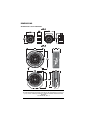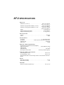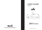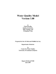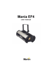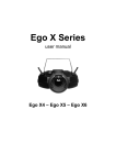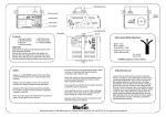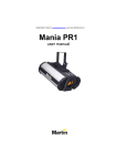
1
AF-1 and AF-2
fans
user manual
DIMENSIONS
All dimensions are in millimeters
AF-1
180
320
390
400
360
AF-2
750
335
770
700
310
680
600
©2005 JEM / Martin Professional A/S, Denmark.
All rights reserved. No part of this manual may be reproduced, in any form or
by any means, without permission in writing from Martin Professional A/S,
Denmark.
P/N 35000166, Rev. A
CONTENTS
Introduction . . . . . . . . . . . . . . . . . . . . . . . . . . . . . . . . . . . . . . . . . . . . . . . . 5
Features . . . . . . . . . . . . . . . . . . . . . . . . . . . . . . . . . . . . . . . . . . . . . . . . . 5
Safety information . . . . . . . . . . . . . . . . . . . . . . . . . . . . . . . . . . . . . . . . . 6
Unpacking . . . . . . . . . . . . . . . . . . . . . . . . . . . . . . . . . . . . . . . . . . . . . . . 7
Installation . . . . . . . . . . . . . . . . . . . . . . . . . . . . . . . . . . . . . . . . . . . . . . . . . 8
AC power . . . . . . . . . . . . . . . . . . . . . . . . . . . . . . . . . . . . . . . . . . . . . . . . 8
Physical installation . . . . . . . . . . . . . . . . . . . . . . . . . . . . . . . . . . . . . . . . 9
Installing control hardware . . . . . . . . . . . . . . . . . . . . . . . . . . . . . . . . . . 11
Remote control installation . . . . . . . . . . . . . . . . . . . . . . . . . . . . . . . . . . 11
AF-1 10 V control installation . . . . . . . . . . . . . . . . . . . . . . . . . . . . . . . . 12
DMX installation . . . . . . . . . . . . . . . . . . . . . . . . . . . . . . . . . . . . . . . . . . 12
Operation . . . . . . . . . . . . . . . . . . . . . . . . . . . . . . . . . . . . . . . . . . . . . . . . . 16
Using fans with smoke machines . . . . . . . . . . . . . . . . . . . . . . . . . . . . . 16
Using fans with smoke ducting . . . . . . . . . . . . . . . . . . . . . . . . . . . . . . . 16
Remote control operation . . . . . . . . . . . . . . . . . . . . . . . . . . . . . . . . . . . 17
DMX control . . . . . . . . . . . . . . . . . . . . . . . . . . . . . . . . . . . . . . . . . . . . . 18
Service and maintenance . . . . . . . . . . . . . . . . . . . . . . . . . . . . . . . . . . . . 19
Cleaning . . . . . . . . . . . . . . . . . . . . . . . . . . . . . . . . . . . . . . . . . . . . . . . . 19
Replacing the main fuse . . . . . . . . . . . . . . . . . . . . . . . . . . . . . . . . . . . . 21
Troubleshooting . . . . . . . . . . . . . . . . . . . . . . . . . . . . . . . . . . . . . . . . . . . 22
AF-1 specifications . . . . . . . . . . . . . . . . . . . . . . . . . . . . . . . . . . . . . . . . . 23
AF-2 specifications . . . . . . . . . . . . . . . . . . . . . . . . . . . . . . . . . . . . . . . . . 25
Connections panels
AF-1 Fan
1 2 3 4 5 6 7 8 910
ON
d
f
e
c
b
g
a
a
b
c
d
h
e
f
g
h
– Analog 0 - 10 V in
– Analog 0- 10 V out
– Remote in
– Power LED
– Data LED
– DIP switch
– DMX in (3-pin XLR)
– DMX out (3-pin XLR)
AF-2 Fan
b
a
c
d
e
i
f
4
g
– Remote in
– Power inlet
– Main fuseholder
– DMX out (5-pin XLR)
– DMX in (5-pin XLR)
– DMX out (3-pin XLR)
– DMX in (3-pin XLR)
– DIP switch
– Data LED
ON
h
a
b
c
d
e
f
g
h
i
1 2 3 4 5 6 7 8 910
AF-1 and AF-2 fans user manual
INTRODUCTION
Thank you for selecting a JEM AF series fan.
The AF-1 and AF-2 fans are powerful machines designed for professional
and semi-professional use in clubs, TV studios, theaters and touring
contexts. They are suitable for a wide range of applications including
smoke and haze dispersal, sending smoke through ducting, wind effects
and cooling performers or equipment. When fans are used at high output
in conjunction with a smoke machine at low output, a perfect haze effect
can be produced.
Both fans have high quality sealed motors designed to withstand the high
condensation levels associated with close proximity smoke
AF-1 and AF-2 fans can be controlled using the remote control unit
supplied with each product or via DMX on a serial data link. They may be
interfaced with ZR12AL, ZR12DMX, ZR22STD, ZR22DMX and ZR33
smoke machines and Club Smoke System to allow simultaneous smoke
and fan operation.
When used in combination with smoke machines, etc., DMX control
allows atmospheric effects to be integrated in the light show directly from
the lighting console. The remote control allows variable fan speed in
continuous or timer operation. When using the built-in timer, operating
periods and intervals between operating periods can be set
independently.
The AF-1 fan can also be controlled using a 0 - 10 V analog controller.
The most recent version of this manual is available under Smoke in the
Support area of the Martin website at: http://www.martin.com
Features
•
•
•
•
•
•
DMX control.
Remote control with instant or timer-controlled operation.
5 meter (16.4 ft.) remote cable.
Variable fan speed.
Adjustable flying bracket offering 180° of tilt
Can be flown or placed on a flat surface
Introduction
5
• Rugged construction.
• Sealed high-quality maintenance-free fan motor offers high airflow, high
resistance to condensation, ingress of dirt, smoke fluid, etc. and low
noise.
The AF-1 can also be controlled singly or on a multiple link using an
analog 0 - 10 V controller.
Safety information
Warning!
This product is not for household use. It presents risks of
lethal or severe injury due to electric shock, falls and fast moving blades.
To reduce the risk of fire or electric shock, do not use this fan
with any solid-state speed control device.
Read this manual before powering or installing the fan, follow the safety
precautions listed below and observe all warnings in this manual and
printed on the machine. If you have questions about how to operate the
machine safely, please contact a JEM/Martin dealer for assistance or call
the Martin 24-hour service hotline on +45 70 200 201.
Refer any service operation not described in this manual to a qualified
technician.
Preventing electric shocks
• Always ground (earth) the machine electrically.
• Use only a source of AC power that complies with local building and
electrical codes, and that has both overload and ground-fault protection.
• Check the AC supply voltage is correct for use with the machine. The
voltage setting is printed on the machine’s serial label.
• Disconnect the machine from power before removing any components
or servicing, and when not in use.
• Moisture can cause dangerous electrical faults. Do not aim fog output at
electrical connections or devices.
• Do not expose this machine to wet conditions – the machine is not
waterproof.
• Do not spill fluid over the machine. If fluid is spilled, disconnect the
machine from power and clean with a damp cloth. If fluid is spilled onto
electronic parts, contact an approved JEM/Martin dealer for advice.
6
AF-1 and AF-2 fans user manual
• Do not dismantle or attempt to repair a faulty machine. Refer all service
to an authorized JEM/Martin service dealer.
• Do not operate the machine if the power cable or connector is
damaged. A damaged cable or connector must be replaced with a new
item, available from your JEM/Martin dealer.
• Do not operate the machine with damaged, deformed or missing parts.
Preventing burns and fire
• Ensure that airflow around the machine is free and unobstructed.
• Do not operate the machine if the ambient temperature (Ta) exceeds
55° C (131° F).
Preventing injuries
• Never allow any object or part of your body to enter the path of the fan
blades, and ensure that clothing, cables or other items cannot be
sucked into the fan.
• Disconnect the fan from power before removing any cover or grill. Do
not operate the fan unless all covers and grills are installed and
securely fastened.
• Ensure that the supporting structure or surface can hold at least 10
times the weight of all installed devices.
• Use an approved means of secondary attachment such as a safety
cable.
• Work from a stable platform and block access below the work area
when installing, servicing or removing the machine.
Unpacking
AF-1 and AF-2 fans are supplied with:
•
•
•
•
Remote control unit with 5 meter (16.5 ft) cable with XLR connector
Power cable
User manual
Adjustable flying bracket
Introduction
7
INSTALLATION
This product must be installed by qualified personnel only.
AC power
AF-1 and AF-2 fans are available in two versions:
• US version: 115 V, 50/60 Hz (for use with 105-115 VAC, 60 Hz power
supplies)
• EU version: 230 V, 50/60 Hz (for use with 220-245 VAC, 50 Hz power
supplies)
Fans are supplied set up to match local voltage and frequency settings.
The factory default setting is shown on the serial number label.
Warning!
For protection from fire and electric shock, AF-1 and AF-2 fans
must be grounded (earthed). The power supply must have
overload and ground-fault protection.
Check that power cables are undamaged and rated for the
current requirements of all connected devices before use.
Check the power supply setting specified on the serial number
label before applying power.
Installin g a cord cap on the power cable
On EU (230 V, 50/60 Hz) models, the power cable must be fitted with a
grounding-type cord cap (earthed mains plug) that fits your power
distribution system. Consult a qualified electrician if you have any doubts
about proper installation.
Wire
Pin
Marking
Screw color
brown
live
“L”
yellow or brass
blue
neutral
“N”
silver
yellow/green
ground
Table 1: Cord cap wiring
8
AF-1 and AF-2 fans user manual
green
Following the cord cap manufacturer’s instructions, connect the yellow
and green wire to ground (earth), the blue wire to neutral and the brown
wire to live. The table on page 8 shows some pin identification schemes:
Physical installation
The AF-1 fan may be suspended from a suitable support such as a truss,
placed on a horizontal surface resting on its rubber feet, or fastened to a
surface.
The AF-2 fan may be suspended from a suitable support such as a truss.
If it is installed in the touring frame available as an accessory, it may be
placed on a horizontal surface resting on the touring frame’s rubber feet.
Both fans can be tilted through 180° and locked in position.
Warning!
The slight vibration of the fan may cause fasteners to loosen.
Check all fasteners regularly for tightness, especially when
the machine is newly installed.
The AF-1 and AF-2 fans must be positioned well out of reach
of the public.
Suspending from a support
Warning!
Block access below the work area and work from a stable
platform when installing, servicing or removing the machine.
Always use a secure secondary attachment that can hold at
least 10 times the weight of the machine.
Rigging clamps, omega brackets and fasteners are
available as accessories from your JEM/Martin dealer.
Any quarter-turn fasteners used must be turned a full
quarter turn clockwise to lock them (see illustration).
1. Verify that any structure used to support the machine
can support at least 10 times the total weight of all installed fixtures,
clamps, cables, auxiliary equipment, etc.
2. Check that all rigging clamps and fasteners are undamaged and can
support at least 10 times the machine’s weight.
• AF-1 fan: Bolt a rigging clamp to the machine’s flying bracket using
a grade 8.8 (minimum) M12 bolt and lock nut, or as recommended
Installation
9
by the clamp manufacturer, through the 13 mm hole in the center of
the mounting bracket.
• AF-2 fan: Two rigging options exist. Either:
a) Bolt two rigging clamps to two Martin standard omega brackets
(P/N 91602001) using grade 8.8 (minimum) M12 bolts and lock
nuts, or as recommended by the clamp manufacturer. Fasten the
two omega brackets to the flying bracket or touring frame. This
option allows the fan to be flown in line with or at 90° to a truss.
or:
b) Bolt one rigging clamp to one Martin 250-300 wide omega
bracket (P/N 91602000). Fasten the wide omega bracket to the
flying bracket or touring frame. This option allows the fan to be
flown at any angle relative to the truss.
Martin standard omega
bracket: P/N 91602001
Martin 250-300 wide omega
bracket: P/N 91602000
3. Clamp the fan to a truss or similar support.
4. Loop a safety wire that can hold at least 10 times the weight of the
machine through/over the support and through the flying bracket or
touring frame.
5. Loosen the swivel locks and tilt the fan to the desired angle. Turn the
swivel locks clockwise to tighten. Check that fan, hardware and safety
attachment are secure before applying power.
Placing on a hori zontal surface
AF-1 and AF-2 fans can be installed on a level horizontal surface:
• The AF-1 can be placed on a surface resting on its rubber feet.
• The AF-2 can be installed in a touring frame (available as an accessory)
and then placed on a surface resting on the frame’s rubber feet.
If the machine is to be placed on a horizontal surface:
• Ensure that the surface is level, stable and capable of supporting at
least ten times the weight of the machine.
• Secure the machine so that it cannot slide or fall, even if air pressure
during full speed operation and vibration are present.
• Eliminate any risk of accidental contact.
10
AF-1 and AF-2 fans user manual
INSTALLING CONTROL HARDWARE
The AF-1 and AF-2 fans can be operated either using the JEM
multifunction remote control unit supplied with each machine, or via DMX
using a DMX control device and serial data link.
The AF-1 can also be operated using a 0 - 10 volt DC analog control
device. Up to four AF-1 fans can be linked in remote and 10 V analog
operation.
Remote control installation
To connect the remote control unit:
1. Power fans off.
2. Plug the XLR connector on the remote control cable into the REMOTE
IN plug on the connections plate (see “Connections panels” on page
4).
3. If linking multiple AF-1 fans, use suitable cable to connect the first
fan’s analog output to the next fan’s analog input, and continue
connecting fans output to input.
4. Reapply power.
The AF-2 touring frame available as an accessory includes a docking
station for the remote control unit (see illustration below). The remote
control can be fastened in place using the two thumbscrews provided,
and the remote cable wrapped around the brackets.
Installing control hardware
11
AF-1 10 V control installation
AF-1 fan speed can be controlled by connecting a suitable analog 0 - 10
volts DC controller via the ANALOG IN connector. Up to four machines
can be linked on an analog control link. To create an analog control link:
1. Power fans off.
2. Connect a suitable cable to the controller’s output and the first fan’s
analog input.
3. Use suitable cable to connect the first fan’s analog output to the next
fan’s analog input, and continue connecting fans output to input.
4. Reapply power.
DMX installation
Up to 32 devices can be controlled on one DMX data link. Devices must
be ‘daisy-chained’ in one continuous line without branches. More devices
can be added and the link can be branched using an optically isolated
splitter/amplifier such as the Martin RS-485 Opto-Splitter (P/N 90758060).
DMX cable connection
A reliable DMX data connection requires suitable cable. Standard
microphone cable cannot transmit DMX data reliably over long runs. For
best results, use shielded cable with at least one twisted pair specifically
designed for RS-485 applications. Your Martin dealer can supply suitable
high quality cable in various lengths.
AF-1 and AF-2 fans both connect to a serial DMX data link via XLR
connectors:
• The AF-1 fan has three-pin XLR connectors for DMX IN and DMX OUT.
• The AF-2 fan has both three-pin and five-pin XLR connectors for DMX
IN and DMX OUT.
All DMX connectors on AF-1 and AF-2 fans are wired with pin 1 to ground,
pin 2 to signal - (cold), and pin 3 to signal + (hot). This is the standard pin
assignment for DMX devices.
12
AF-1 and AF-2 fans user manual
To connect to devices with reversed polarity, use a phase-reversing
adaptor (P/N 11820006).
To connect the AF-1 to a device with a 5-pin output, use a 5-pin male to 3pin female XLR adaptor cable (P/N 11820005). To connect the AF-1 to a
device with a 5-pin input, use a 3-pin male to 5-pin female adaptor cable
(P/N 11820004).
5-pin to 3-pin
Adaptor
3-pin to 5-pin
Adaptor
Male
Female
Male
Female
Male
Female
1
2
3
4
5
1
2
3
1
2
3
1
2
3
4
5
1
2
3
1
2
3
P/N 11820005
P/N 11820004
3-pin to 3-pin
Phase-Reversing
Adaptor
P/N 11820006
DMX adaptors: connection pins and polarity
To connect the DMX data link:
1. Power all devices off.
2. Connect a data cable from the controller’s DMX data output to the first
device’s DMX input
3. Connect the DMX output of this device to the DMX input of the next
device.
4. Continue connecting up to a total of 32 devices in one single line,
output to input.
5. Terminate the link by inserting a male termination plug (available from
your Martin dealer: P/N 91613017) into the data output of the last
device. A termination plug is simply an XLR connector with a 120
Ohm, 0.25 W resistor soldered across pins 2 and 3.
Specifying DMX control channels
AF-1 and AF-2 fans use a single DMX control channel to receive
instructions from the controller. This control channel is the DMX address.
To control machines individually, each must have its own unique DMX
address. To control identical machines as a group, they can all be given
the same DMX address. They will then receive the same instructions and
should behave identically. Setting up identical fixtures with the same DMX
address can also be a good tool for troubleshooting unexpected behavior.
Installing control hardware
13
The DMX address on AF-1 and AF-2 fans can be set to any channel from
1 to 512 using DIP-switch pins 1 - 10:
1. Decide on an available DMX address for each machine.
2. Look up the DIP-switch settings using the Martin Address Calculator at
http://www.martin.dk/service/utilities/AddrCalc/index.asp, or look for
the address in the DIP-switch settings table on page 15. For example,
to set the DMX address to 101, you need to set DIP-switch pins 1, 3, 6
and 7 to ON, as shown in the illustration below:
3. Power the controller and all devices off.
4. For each device, set the DMX address by setting DIP-switch pins 1
through 10 to the ON (1) or OFF (0) position as listed in the table on
the next page. As an example, channel 101 is highlighted in the table.
14
AF-1 and AF-2 fans user manual
DMX address DIP-switch settings
To use this table, first find the DMX address in the main block in the table.
Then read the settings for pins 1 - 5 to the left and read the settings for
pins 6 - 9 above the address. “0” means OFF and “1” means ON.
For example, to set the DMX address to 101, you need to set DIP-switch
pins 1, 3, 6 and 7 to ON, as highlighted in the table.
DIP switch pins setting
0 = OFF
1 = ON
#1
0
1
0
1
0
1
0
1
0
1
0
1
0
1
0
1
0
1
0
1
0
1
0
1
0
1
0
1
0
1
0
1
#2
0
0
1
1
0
0
1
1
0
0
1
1
0
0
1
1
0
0
1
1
0
0
1
1
0
0
1
1
0
0
1
1
#3
0
0
0
0
1
1
1
1
0
0
0
0
1
1
1
1
0
0
0
0
1
1
1
1
0
0
0
0
1
1
1
1
#4
0
0
0
0
0
0
0
0
1
1
1
1
1
1
1
1
0
0
0
0
0
0
0
0
1
1
1
1
1
1
1
1
#5
0
0
0
0
0
0
0
0
0
0
0
0
0
0
0
0
1
1
1
1
1
1
1
1
1
1
1
1
1
1
1
1
#9
#8
#7
#6
0
0
0
0
0
0
0
1
0
0
1
0
0
0
1
1
0
1
0
0
0
1
0
1
0
1
1
0
0
1
1
1
1
0
0
0
1
0
0
1
1
0
1
0
1
0
1
1
1
1
0
0
1
1
0
1
1
1
1
0
1
1
1
1
1
2
3
4
5
6
7
8
9
10
11
12
13
14
15
16
17
18
19
20
21
22
23
24
25
26
27
28
29
30
31
32
33
34
35
36
37
38
39
40
41
42
43
44
45
46
47
48
49
50
51
52
53
54
55
56
57
58
59
60
61
62
63
64
65
66
67
68
69
70
71
72
73
74
75
76
77
78
79
80
81
82
83
84
85
86
87
88
89
90
91
92
93
94
95
96
97
98
99
100
101
102
103
104
105
106
107
108
109
110
111
112
113
114
115
116
117
118
119
120
121
122
123
124
125
126
127
128
129
130
131
132
133
134
135
136
137
138
139
140
141
142
143
144
145
146
147
148
149
150
151
152
153
154
155
156
157
158
159
160
161
162
163
164
165
166
167
168
169
170
171
172
173
174
175
176
177
178
179
180
181
182
183
184
185
186
187
188
189
190
191
192
193
194
195
196
197
198
199
200
201
202
203
204
205
206
207
208
209
210
211
212
213
214
215
216
217
218
219
220
221
222
223
224
225
226
227
228
229
230
231
232
233
234
235
236
237
238
239
240
241
242
243
244
245
246
247
248
249
250
251
252
253
254
255
256
257
258
259
260
261
262
263
264
265
266
267
268
269
270
271
272
273
274
275
276
277
278
279
280
281
282
283
284
285
286
287
288
289
290
291
292
293
294
295
296
297
298
299
300
301
302
303
304
305
306
307
308
309
310
311
312
313
314
315
316
317
318
319
320
321
322
323
324
325
326
327
328
329
330
331
332
333
334
335
336
337
338
339
340
341
342
343
344
345
346
347
348
349
350
351
352
353
354
355
356
357
358
359
360
361
362
363
364
365
366
367
368
369
370
371
372
373
374
375
376
377
378
379
380
381
382
383
384
385
386
387
388
389
390
391
392
393
394
395
396
397
398
399
400
401
402
403
404
405
406
407
408
409
410
411
412
413
414
415
416
417
418
419
420
421
422
423
424
425
426
427
428
429
430
431
432
433
434
435
436
437
438
439
440
441
442
443
444
445
446
447
448
449
450
451
452
453
454
455
456
457
458
459
460
461
462
463
464
465
466
467
468
469
470
471
472
473
474
475
476
477
478
479
480
481
482
483
484
485
486
487
488
489
490
491
492
493
494
495
496
497
498
499
500
501
502
503
504
505
506
507
508
509
510
511
Table 2: DMX address DIP-switch settings
Installing control hardware
15
OPERATION
Before powering on, check that the fan is correctly and safely installed.
Using fans with smoke machines
When using a fan in
combination with a
smoke machine, fog
machine or hazer,
place the fan behind
the machine, as
illustrated on the
right. Do not place
the fan in front of the
machine and direct
the output from the
machine into the fan,
as this will cause
undesirable residue
build-up and the fan
blades will degrade
the quality of the
smoke.
Using fans with smoke ducting
To avoid residue build-up and preserve smoke quality, connect fans to
smoke ducting using a Y-shaped arrangement, placing the fan on one arm
of the Y and the smoke machine on the other.
16
AF-1 and AF-2 fans user manual
Remote control operation
Multifunction controller overview
Jem
B
C
D
TIMER
ON
MULTI-FUNCTION
CONTROLLER
AF-2
A
ON
4
ON
5
6
4
7
3
2
1
4
7
POWER
E
9
10
0
CYCLE
DELAY
F
5
6
3
7
1
9
2
8
1
SPEED
ON
6
2
9
10
5
3
8
0
x8
G
8
10
0
RUN
H
i
A INSTANT FAN OPERATION BUTTON – Press to run the fan
at the speed set on the fan speed control.
B STANDBY – Puts the fan into standby mode. Must be set
to ON to operate in any mode.
C TIMER VALUE BUTTON – When timer is active, adjusts
timer values by a factor of 8 (i.e. a 5 second run time
becomes 40 seconds and a 10 second delay time
becomes 1 minute 20 seconds).
D TIMER ENGAGE – Engages the timer to run the fan
according to the timer settings.
E SPEED – Sets fan speed from minimum to maximum.
F POWER LED – Lights when power is on.
G DELAY TIME CONTROL – Sets intervals between
operating periods during timer-controlled operation.
H CYCLE LED – Lights during timer-controlled operation.
I
RUN TIME CONTROL – Sets duration of operating periods
during timer-controlled operation.
The multifunction remote control unit supplied with the AF-1 and AF-2
fans allows instant or timer-controlled fan operation and airflow control.
The unit also gives feedback on the status of the machine.
Operation
17
To set timer operation using the remote control:
1. Set the desired amount of airflow using the SPEED control
2. Set intervals between operating periods by setting the DELAY control
to between 1 and 9.
3. Set duration of operating periods by setting the RUN control to
between 1 and 9.
4. Set the STANDBY button to ON
5. Set the TIMER ON button to ON.
The CYCLE LED lights when the timer function is active.
To extend timer settings, press the X8 button. This will multiply both RUN
and DELAY times by 8.
DMX control
Fan speed on the AF-1 and AF-2 fans can be controlled using a DMX
controller.
DMX controller operation
When a fan is powered on, the Data LED next to the DIP-switch will light
when a valid DMX signal is received.
Increase the value on the machine’s DMX control channel to increase fan
speed as shown below:
DMX control channel levels
18
Level
Percentage
Effect
0-27
28-255
0-10%
11-100%
Fan speed zero.
1 - 100% fan speed.
AF-1 and AF-2 fans user manual
SERVICE AND MAINTENANCE
Any service procedure not described here should be referred to a
qualified technician.
Disconnect the fan from power before removing any grills or
covers.
Cleaning
Clean the outside of the fan with a damp cloth only. Do not use solvents.
Periodic cleaning of the fan blades and grills is necessary to maintain
peak performance. Cleaning intervals will depend on the operating
environment. Inspect the fan regularly for dust and smoke residue
buildup, and clean as soon as there is significant dirt buildup on fan
blades or at the first signs that airflow through grills may be restricted.
Use a soft brush and vacuum to clean grills and fan blades.
AF-1 cleaning access
1. Disconnect the fan
from power.
ON
2. Remove the four
cross-head screws (A)
as illustrated, and lift
the grill/motor
assembly clear of the
housing. The motor
cable (B) will remain
attached to the motor
and the housing.
Avoid straining the
cable.
A
1 2 3 4 5 6 7 8 910
Warning!
B
A
3. After cleaning, replace
the grill and screws,
ensuring that screws
are securely
tightened.
Service and maintenance
A
A
19
AF -2 cleaning access
1. Disconnect the fan from power.
2. Remove the 16 cross-head screws from the covers (see illustration
above), and remove the covers.
3. Reaching into the fan housing for
access to the locking nuts,
remove the four 6mm Allen
screws holding the front grill (see
illustration on right), collecting all
washers and grommets for reuse.
Note: the front grill is on the
opposite side from the fan motor.
It should be possible to clean the
machine without removing the
rear grill that holds the fan motor.
4. After cleaning, replace the screws and front grill. Reassemble exactly
as shown in the next illustration, making sure that the rubber
20
AF-1 and AF-2 fans user manual
grommets (A) are seated in the fan housing (B). If this assembly
sequence is not respected, the AF-2 will be excessively noisy.
B
A
Replacing the main fuse
The main fuse can be replaced by the user if necessary. An indication that
the main fuse may have blown is that the Power LED (on the AF-1 only) or
the Data status LED (on AF-1 and AF-2 fans) does not light when:
• power is applied, and
• the remote control or a valid DMX signal is present.
Never bypass the fuse or replace it with one of another size or rating.
To replace the main fuse:
1. Disconnect the power cable from the fan.
2. Use a screwdriver to lever the fuseholder out
of the power inlet socket (see illustration).
3. Replace the fuse with one of the same rating
and type. Fuse details are given on the serial
number label and in the Specifications
sections of this manual.
4. Replace the fuseholder and reconnect to power.
If the fuse blows repeatedly, disconnect the machine from power and from
control equipment and contact your Martin/JEM dealer for service.
Service and maintenance
21
TROUBLESHOOTING
Problem
No light from status
LEDs on remote control
or fan
Power is applied, but no
fan action using DMX
Excessively noisy
operation
Reduced airflow
22
Probable cause(s)
Suggested remedy
No power
Check power supply and
connections
Remote control not set to
Standby
Press Standby button
Remote control not
connected
Check connections
Fuse blown
Replace fuse with one of
same type and rating.
If fuse blows repeatedly,
consult your JEM/Martin
dealer.
Incorrect DMX address
Check DIP-switch
settings
No DMX termination
Fit termination plug to
last device on DMX link
Grill loose
Check and tighten grill
retaining screws
AF-2: Incorrectly
assembled grill mounting
hardware
Check, and if necessary
reassemble (see “AF-2
cleaning access” on
page 20)
Grills and/or fan blades
dirty
Check and clean
Low supply voltage
Check AC supply
AF-1 and AF-2 fans user manual
AF-1 SPECIFICATIONS
Physical
Dimensions (L x W x H) . . . . . . . . . . . . . . . . . . . . . . . . . . . 320 x 180 x 360 mm
(12.6 x 7.1 x 14.2 in.)
Dimensions in flying bracket (L x W x H) . . . . . . . . . . . . . . 390 x 180 x 400 mm
(15.4 x 7.1 x 15.8 in.)
Weight including flying bracket. . . . . . . . . . . . . . . . . . . . . . . . . . . 10 kg (22 lb.)
Construction
Housing . . . . . . . . . . . . . . . . . . . . . . . . . . . . . . . . . . . . . . . . . . . . . . . . . . . Steel
Finish . . . . . . . . . . . . . . . . . . . . . . . . . . . . . . . . . . . . . . . . . . . . . . . . . . . . . Black
Performance
Fan Speed . . . . . . . . . . . . . . . . . . . . . . . . . . . . . . . . . . . 0 - 2500 rpm @ 50 Hz
Air Volume . . . . . . . . . . . . . . . . . . . . . 1815 m3per hour (64,096 cu.ft.per hour)
Operation Time. . . . . . . . . . . . . . . . . . . . . . . . . . . . . . . . . . . . . . . . . Continuous
Noise Level. . . . . . . . . . . . . . . . . . . . . . . . . . . . . . . . . . . . . . . . . . . . . . . 70 dBA
Control and programming
Multifunction remote control unit (supplied)
DMX control protocol . . . . . . . . . . . . . . . . . . . . . . . . . . USITT DMX-512 (1990)
DMX channels . . . . . . . . . . . . . . . . . . . . . . . . . . . . . . . . . . . . . . . . . . . . . . . . . 1
DMX addressing . . . . . . . . . . . . . . . . . . . . . . . . . . . . . . . . . . . . . . . DIP-switch
0-10V analog control
Analog link . . . . . . . . . . . . . . . . . . . . . . . . . . . . Standard via 3-pin XLR socket
Max length of remote cable . . . . . . . . . . . . . . . . 50 metres (5 metres supplied)
Thermal
Maximum ambient temperature (Ta) . . . . . . . . . . . . . . . . . . . . . . .55°C (131°F)
Connections
Remote control . 3-pin locking XLR, pin 1 shield, pin 2 +15V, pin 3 signal 0-10V
DMX . . . . . . . . . . . . 3-pin locking XLR, pin 1 shield, pin 2 cold (-), pin 3 hot (+)
0 - 10 V analog . . . . . . . . . . . . . . . . . . . . . . . . . . . . . . . . . . . . 3-pin locking XLR
AC power . . . . . . . . . . . . . . . . . . . . . . . . . . . . . . . . . . . . . . . . . . IEC power inlet
Typical power and current
US model @115 V, 60 Hz . . . . . . . . . . . . . . . . . . . . . . . . . . . . . . . 175 W, 1.8 A
EU model @ 230 V, 50 Hz . . . . . . . . . . . . . . . . . . . . . . . . . . . . . . 120 W, 0.5 A
Measurements taken at nominal voltage. Allow for ±10% deviation from these figures.
AF-1 specifications
23
Fuses
Main fuse (US model) . . . . . . . . . . . . . . . . . . . . . . . . . . . . . . . . . . . . . . . . 5 AT
Main fuse (EU model) . . . . . . . . . . . . . . . . . . . . . . . . . . . . . . . . . . . . . . 3.15 AT
Installation
Orientation . . . . . . . . . . . . . . . . . . . . . . . . . . . . . . . . . . . . . . . . . . . . . . . . . . any
Minimum clearance around machine . . . . . . . . . . . . . . . . . . . . . . 0.1 m (4 in.)
Approvals
CE
UL 507, 9 th ed., incl. revisions through 09/24/01 (pending)
CSA C22.2 No 113-1984, reaffirmed 1993 (pending)
Included items (US model)
3 m (9.8 ft) IEC power cable 18 AWG with US male connector (UL approved)
User manual
JEM multifunction remote control with 5 m (16.4 ft) cable and XLR connector
Adjustable flying bracket
Included items (EU model)
2m (6.5 ft) IEC power cable 3 x 1.0mm2
User manual
JEM multifunction remote control with 5 m (16.4 ft) cable and XLR connector
Adjustable flying bracket
Accessories
G-clamp . . . . . . . . . . . . . . . . . . . . . . . . . . . . . . . . . . . . . . . . . . . .P/N 91602003
Half-coupler clamp . . . . . . . . . . . . . . . . . . . . . . . . . . . . . . . . . . .P/N 91602005
DMX termination plug (end of link), XLR male . . . . . . . . . . . . . .P/N 91613017
5-pin male to 3-pin female XLR adaptor cable . . . . . . . . . . . . . . P/N 11820005
Ordering information
AF-1 DMX Fan (US model: 110/120V, 50/60 Hz) . . . . . . . . . . . .P/N 92615100
AF-1 DMX Fan (EU model: 220/240 V, 50/60 Hz) . . . . . . . . . . . .P/N 92615000
Specifications subject to change.
AF-2 SPECIFICATIONS
Physical
Dimensions (L x W x H) . . . . . . . . . . . . . . . . . . . . . . . . . . . 600 x 310 x 600 mm
(23.7 x 12.2 x 23.7 in.)
Dimensions, flying bracket installed (L x W X H) . . . . . . . . 700 x 310 x 680 mm
(27.6 x 12.2 x 26.8 in.)
Dimensions, touring frame installed (L x W x H) . . . . . . . . 750 x 335 x 770 mm
(29.6 x 13.2 x 30.4 in.)
Weight . . . . . . . . . . . . . . . . . . . . . . . . . . . . . . . . . . . . . . . . . . 15.7 kg (34.7 lb.)
Weight including flying bracket. . . . . . . . . . . . . . . . . . . . . . . . .17.5 kg (38.6 lb.)
Weight including touring frame. . . . . . . . . . . . . . . . . . . . . . . . .21.4 kg (47.2 lb.)
Construction
Housing . . . . . . . . . . . . . . . . . . . . . . . . . . . . . . . . . . . . . . . . . . . . . . . Aluminum
Finish . . . . . . . . . . . . . . . . . . . . . . . . . . . . . . . . . . . . . . . . . . . . . . . . . . . . . Black
Performance
Fan Speed . . . . . . . . . . . . . . . . . . . . . . . . . . . . . . . . . . . 0 - 1400 rpm @ 50 Hz
Air Volume . . . . . . . . . . . . . . . . . . . 5700 m3 per hour (201,293 cu.ft. per hour)
Operation Time. . . . . . . . . . . . . . . . . . . . . . . . . . . . . . . . . . . . . . . . . Continuous
Noise Level. . . . . . . . . . . . . . . . . . . . . . . . . . . . . . . . . . . . . . . . . . . . . . . 73 dBA
Control and programming
JEM Multifunction remote control unit (supplied)
DMX control protocol . . . . . . . . . . . . . . . . . . . . . . . . . . USITT DMX-512 (1990)
DMX channels . . . . . . . . . . . . . . . . . . . . . . . . . . . . . . . . . . . . . . . . . . . . . . . . . 1
DMX addressing . . . . . . . . . . . . . . . . . . . . . . . . . . . . . . . . . . . . . . . DIP-switch
Max length of remote cable . . . . . . . . . . . . . . . . 50 metres (5 metres supplied)
Typical power and current
US model @115 V, 60 Hz . . . . . . . . . . . . . . . . . . . . . . . . . . . . . . . 335 W, 3.3 A
EU model @ 230 V, 50 Hz . . . . . . . . . . . . . . . . . . . . . . . . . . . . . . 245 W, 1.2 A
Measurements taken at nominal voltage. Allow for ±10% deviation from these
figures.
Fuses
Main fuse (US model) . . . . . . . . . . . . . . . . . . . . . . . . . . . . . . . . . . . . . . . 6.3 AT
Main fuse (EU model) . . . . . . . . . . . . . . . . . . . . . . . . . . . . . . . . . . . . . . . . 5 AT
Thermal
Maximum ambient temperature (Ta) . . . . . . . . . . . . . . . . . . . . . . .55°C (131°F)
Connections
Remote control . 3-pin locking XLR, pin 1 shield, pin 2 +15V, pin 3 signal 0-10V
DMX . . . . . . . . . . . . 3-pin locking XLR, pin 1 shield, pin 2 cold (-), pin 3 hot (+)
AC power . . . . . . . . . . . . . . . . . . . . . . . . . . . . . . . . . . . . . . . . . . IEC power inlet
Installation
Orientation . . . . . . . . . . . . . . . . . . . . . . . . . . . . . . . . . . . . . . . . . . . . . . . . . . any
Minimum clearance around machine . . . . . . . . . . . . . . . . . . . . . . 0.1 m (4 in.)
Approvals
CE
UL 507, 9 th ed., incl. revisions through 09/24/01 (pending)
CSA C22.2 No 113-1984, reaffirmed 1993 (pending)
Included items (US model)
3m (9.8 ft) IEC power cable 18AWG with US male connector (UL approved)
User manual
JEM multifunction remote control with 5 m (16.4 ft) cable and XLR connector
Adjustable flying bracket
Included items (EU model)
2m (6.5 ft) IEC power cable 3 x 1.0mm2
User manual
JEM multifunction remote control with 5 m (16.4 ft) cable and XLR connector
Adjustable flying bracket
Accessories
Touring frame, AF-2 . . . . . . . . . . . . . . . . . . . . . . . . . . . . . . . . . . .P/N 92620006
Wide omega bracket 250-300 with 4 x quarter-turn fasteners . . .P/N 91602000
Standard omega bracket with 2 x quarter-turn fasteners . . . . . . .P/N 91602001
G-clamp . . . . . . . . . . . . . . . . . . . . . . . . . . . . . . . . . . . . . . . . . . . .P/N 91602003
Half-coupler clamp . . . . . . . . . . . . . . . . . . . . . . . . . . . . . . . . . . .P/N 91602005
DMX termination plug (end of link), XLR male . . . . . . . . . . . . . .P/N 91613017
5-pin male to 3-pin female XLR adaptor cable . . . . . . . . . . . . . . P/N 11820005
Ordering information
AF-2 DMX Fan (US model: 115 V, 50/60 Hz) . . . . . . . . . . . . . . .P/N 92615400
AF-2 DMX Fan (EU model: 230 V, 50/60 Hz) . . . . . . . . . . . . . . .P/N 92615300
Specifications subject to change.
www.martin.com • Olof Palmes Allé 18 • 8200 Aarhus N • Denmark
Tel: +45 8740 0000 • Fax +45 8740 0010