1
Load Controller II
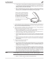
b. In some cases, a hole may have to be drilled to allow access for the harness. Drill
a 1” diameter hole and install the provided grommet (fig. 8). It will be necessary to
seal any grommets or holes that have been cut, drilled or removed so as not to allow
elements to enter the cab area of the vehicle.
c. When routing wiring harness #2 from the compressor, it should not be routed so as
to lay on, or near, the exhaust pipe/muffler/catalytic convertor of the vehicle. Routing
along the top of a crossmember or over a heat shield is recommended.
After the hole is drilled and before
you route the harness to through the
firewall, insert the grommet and “walk”
the material around the inside edge of
the dilled hole. You may have to trim
the grommet to get an exact fit.
(The flexible grommet is in the sealed
parts package.)
fig. 8
7. Connect wiring harness #2 to wiring harness #1 inside the vehicle by connecting the red
wire from harness #2 and the banded and no tape air lines to the low pressure sensors.
See fig. 5 for air line and electrical connection.
8. The next connection is between each air spring and the air line “T” fitting located just
ahead of the check valves in harness #2 (fig. 1 and 7).
a. With the air springs deflated, use a hose cutter or razor blade to cut the air line
already installed between the air springs and the inflation valves.
b. Install the provided “T” fittings (fig. 1) by pushing the air line into each leg of the “T”
until you feel a definite “click”. Each line should go in 9/16”.
c. Connect a single length of air line to the open leg of each “T”. Bring each of the lines
to the “T” fittings in harness #2 just in front of the check valves and connect as shown
in fig. 7.
d. Route the air line across the chassis from the far side over the exhaust system heat
shields and along the frame up to the compressor. Avoid heat sources, sharp edges,
and tight bends.
9. Connect the power wire from harness #1.
a. Route it to the vehicle fuse box.
b. Use a test light to determine which open terminal (accessory, etc.) works only when
the key is in the “on” or accessory position (or refer to the owners manual for an
available accessory fuse). The terminal should have an amperage rating equal to
or higher than the 15 amp in-line fuse.
c. Connection to the fuse terminal will depend on what type of fuse your vehicle uses.
If your vehicle uses the barrel type fuse, use adapter #1. If you have the standard
spade type fuses, use adapter #2. Many late model vehicles use a smaller spade
type fuse which requires adapter #3 (see inset with fig. 1). If adapter #1 or #2 are
used, it will be necessary to cut off the ¼” female connector attached to the power
wire and crimp the smaller 3/16” female connector supplied with this kit.
NOTE
Connect adapter to “HOT” side of the fuse (use a test light to determine). With the ignition
on, the compressor will turn on and fill the system to 10 p.s.i. before shutting off.
10. Connect the gauge light.
a. Attach a ¼” female connector to both the red and black wires.
MN-337
7