1
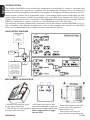
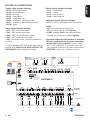
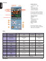
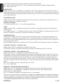
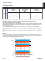
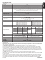
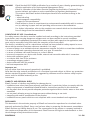
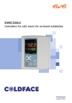
EWHT800LX
Controllers for cold rooms and curing rooms for
on-board installation
English
INTRODUCTION
The Coldface EWHT800LX series controls the temperature and humidity of a static or ventilated cold
room. The curing cycle consists of 1 program with 8 customisable climate profiles. The instrument
controls positive and negative cold rooms and is capable of managing a double evaporator and condenser probes. Coldface has 8 configurable relays, 4 low-voltage digital inputs configurable for door
switch, alarm and pressure. Models are available with clock with yearly calendar and HACCP event
logging. The instrument can be connected to TelevisSystem via the optional plug-in module. The box
allows for installation of a power contactor or a disconnecting switch with door lock.
This summary document contains basic information about the standard models EWHT800LX. For further information and different configurations, refer to the complete user manual p/n 9MA10024
which can be downloaded free of charge from the www.eliwell.it website.
NAVIGATION DIAGRAM
Display alarms
if active
display
probe values
display
probe values
Pb1
-20.6
Pb2
-20.6
Display
HACCP alarms
if function active
1 sec
rtc
18.55
1 sec
3 sec
Manual
defrost
SP1
-18.9
SetPoint & Probes
set
time and date
modifty
SetPoint value
confirm with
1 sec
Functions menu
System
info
PAr
LitE
3 sec
LOC keyboard lock
rSE activate reduced Set
rPA Pressure switch alarms
rEd disable HACCP
rHC reset HACCP alarms
nAD Day/Night
Aut Automatic regulation
St Start Climate Profile
rSt Reset Climate Profile
USR
InS
Parameters
SEt
0.0
see manual
modify
value
confirm
with
diF
2.00
see manual
HSE
50.0
ON / OFF function
MECHANICAL INSTALLATION
• Remove the protective plate
on the right of the door
• Take out the 2 screws supplied
and then open the cover.
EWHT800LX
• Drill holes in the top (or bottom) of the backplate to pass the
high and low-voltage wires through.
Cable clamps must be no bigger
than size PG29
• Screw the backplate to the wall
using 4 screws (not supplied) to
match the holes A...D.
• Shut the door and cover the
screws with the corresponding plate
2 - EN
ELECTRICAL CONNECTIONS
Analogue Output (default settings)
• AO = 0-10V for piloting external fan module
Serials
• TTL for connection to Copy Card
• TTL for connection to TelevisSystem
• RS485 available ONLY with optional Plugin
module for connection to TelevisSystem.
Probe inputs (default settings)
• Pb1 = NTC cold room probe
• Pb2 = NTC defrost end probe
• Pb3 = NTC (de)stratification probe
• Pb4 = NTC condenser fan probe
• Pb5 = Humidity probe / pressure transducer
4...20mA
Important! Make sure the machine is switched
off before working on the electrical connections.
• Removable screw terminals: electric cables
of 2.5 mm2 maximum cross-section (one wire
per terminal in the case of power connections).
• FASTONS: single row of fastons in series.
Pb5
0...10V PWM
10V 55mA GND
+
Analogue
Output - AO 0...20mA GND
4..20mA
+12V
51 52 53
RS 485
39 40 41
Analogue
Output - AO
39 40 41
RS-485
Pb5
485+
485GND
TTL
Pb4
I
-
To switch between NTC/PTC probe types use parameter H00. SWITCH OFF AND RESTART THE
INSTRUMENT after making the change
Bus
Adapter
English
Digital Inputs (default settings)
• D.I.1 = Door switch
• D.I.2 = Alarm
• D.I.3 = Low pressure
• D.I.4 = High pressure
Output relay (default settings)
•OUT1 = Dehumidification
•OUT2 = Humidification
•OUT3 = Heating
•OUT4 = Compressor
•OUT5 = Evaporator fan
•OUT6 = Auxiliary 1 (ventilation fans)
•OUT7 = Auxiliary 2 (destratification fans)
•OUT8 = Light
I (4...20mA)
Pb3
39 40 41 45 46 47 51 52 53 54 55 56 57
Pb2
Pb1
DI4
59 60 61 62
DI3
DI2
DI1
64 65 66 67 68 69 70 71
TTL
RS-485
RS485 connection to
TelevisSystem available
with optional plug-in
module only
Keyboard
EWHT800 LX
Copy
Card
Copy Card
Power
Supply
100...240V
2 3 4 5
8 9 10 11 12 13
14 15 16 17 18 19 20 21 22 23 24
25 26 27 28 29 30
Removable
Terminals
31 32
Faston
AUX 2
+
AUX 1
-
Default configuration
LINE
NEUTRAL
3 - EN
OUT8
OUT7
OUT6
OUT5
OUT4
H28
H27
H26
H25
H24
OUT3 OUT2
H23
H22
OUT1
H21
Relais
Parameters
EWHT800LX
English
DISPLAY
1
10 9 8
2
3
4
5
6
14 13 12 11
7
If the upper display is blinking
it means that the value of the
lower display can be modified
UPPER DISPLAY
%
LOWER DISPLAY
UPPER DISPLAY
• 3 digits and - sign:
View:
• Operating value
• parameters label
• alarms, functions
R.H.
LOWER DISPLAY
• 4 digits
View:
• parameters value
• probe values
• function state
HACCP models
• time
CLIMATE PROFILE STEP
A
B
C
D
E
If the lower display is blinking it means that the displayed
value can be modified
G
F
H
LEDs
No.
LEDs
colour
ON
BLINKING
OFF
1
2
EVAPORATOR FANS
CONDENSER FANS
yellow
yellow
Fans ON
Fans ON
Forced ventilation
/
Fans OFF
Fans OFF
3
VENTILATION FANS
AUXILIARY 1 (AUX))
yellow
VENTILATION FANS
AUX1 ON
/
VENTILATION FANS
AUX1 OFF
DESTRATIFICATION FANS
yellow
AUXILIARY 2 (AUX)
5
HACCP
red
6
ALARM
red
7
COMPRESSOR
yellow
8
DEFROST
yellow
9
HEATING
yellow
10
HUMIDIFICATION
yellow
11
DEHUMIDIFICATION
yellow
12
LIGHT
yellow
ENERGY
13
yellow
SAVING
14
NIGHT & DAY
yellow
STEP
CLIMATE PROFILE
green
ON: function / alarm active; OFF: function / alarm NOT active
EWHT800LX
4
DESTRATIFICATION FANS
AUX2 ON
HACCP alarm
Alarm
Compressor ON
defrost
Heating ON
Humidify
Dehumidify
Light ON
Not displayed
Silenced
Delay
drip
/
/
/
/
Energy saving ON
/
Night & Day ON
/
/
see Climate Profiles
DESTRATIFICATION FANS
AUX2 OFF
No alarm
No alarm
Compressor OFF
No defrost
Heating OFF
Light OFF
Energy saving OFF
Night & Day OFF
4 - EN
KEYS
KEY
A
p UP
B
ESC
C
SET
D
q DOWN
E
F
G
H
START/STOP
RESET
ON/OFF
LIGHT
AUX1/2
press and release
•Alarms Menu (always visible)*
• Scroll
• Increase values
• Exit
• Functions menu
• Display SetPoint / probe values / time*
• Confirm values
• Access value edit mode
(upper display blinking)
• Scroll
• Decrease values
• Display instrument INFO**
• Start Climate Profile
• Stop Climate Profile
/
/
Activate destratification fans
press and hold for about 3 seconds
Notes
/
*HACCP alarms/system alarms
if present
• Manual defrost
• Return to Main Menu
Access Parameter Edit mode
/
**See Technical Support
• Reset Climate Profile
See Climate Profiles
Switch device On/Off
Switch light on/off
Activate destratification fans
USER INTERFACE
How to modify the SetPoint
• Press and release the SET key. The upper display will show SP1, the lower display will indicate the
current SetPoint value
• Press and release the SET key once more. The upper display will show SP1 blinking
• Use the UP & DOWN keys to adjust the SetPoint value
• Press the ESC key several times (or keep it pressed) to return to the normal display
How to read the probe values
• Press and release the SET key. The upper display will show SP1, the lower display will indicate the
current SetPoint value
• Press and release the DOWN key. If the RTC clock is present, the time will be shown in the lower display
• Press and release the DOWN key once more. The upper display will show Pb1, the lower display
will indicate the value read by the room probe
• Press and release the DOWN key once more to read the value of probe Pb2 and Pb3
• Press the ESC key to return to the normal display
How to modify the Lite Parameters
The Lite parameters are the most useful parameters and are described in this document, in
the section Parameters Table.
1) Press and hold the SET key for 3 seconds until the display shows PAr / Lite
2) Press and release the SET key once more. The upper display will show the first parameter*, the
lower display will indicate the current parameter value
3) Using the UP & DOWN keys, find the parameter that you wish to modify
4) Press and release the SET key once more. The upper display will show the name of the blinking
parameter
5) Use the UP & DOWN to adjust the parameter value
6) Press and release SET to save the parameter value
7) Return to step 3) or press ESC several times to return to the normal display
5 - EN
EWHT800LX
English
Nr.
English
LITE PARAMETER TABLE
This section describes the most useful parameters, which are contained in the 'Lite' folder. For a description of all User (USr) and Installer (Ins)
parameters, see the user manual. Note: the 'Lite' folder parameters are NOT divided into subfolders and are always visible (no access password
is required). The same parameters are also visible in the respective folders 'Compressor', 'Fans', etc. (also indicated here for easy reference) in the
User (USr) and Installer (Ins) parameters menu.
PARA. DESCRIPTION
RANGE DEF. / U.o.M.
SP1 SETPOINT Control value within the range between the minimum set point LSE and the maximum set point HSE. LSE...HSE 0.0 °C/°F
Compressor relay activation differential; the compressor stops on reaching the set point value (as indicated by the
diF regulation probe) and restarts at a temperature value equal to the set point plus the value of the differential. Note: 0.1...30.0 2.0 °C/°F
the value 0 cannot be set.
HSE Maximum value that can be assigned to the setpoint.
LSE...302 50.0 °C/°F
LSE Minimum value that can be assigned to the setpoint.
-55.0...HSE -50.0 °C/°F
Humidity setpoint. Minimum LSH value that can be assigned to the setpoint. Maximum HSH value that can be
SPH
LSH...HSH 0.0 %RH
assigned to the setpoint.
dbH Humidity intervention half-band. Always positive.
0.0...50.0 5.0 %RH
Type of defrost.
0= electric defrosting - compressor off (OFF) during defrosting
dtY
0/1/2
0
1 = reverse cycle defrost (hot gas) - compressor ON during defrosting
2= Free: defrosting independently of compressor
Interval between the start of two subsequent defrosting cycles.
0...250
6h
dit
0= function disabled (defrosting NEVER performed)
dEt Defrost time-out; determines the maximum duration of the defrost cycle.
1...250
30 min
dSt Defrost end temperature (determined by the evaporator probe Pb2).
-50.0...150 6.0 °C/°F
Fan stop temperature; if the evaporator probe reads a higher value than the set value, the fans are stopped. The
FSt value is either positive or negative and, depending on parameter FPt, can be either the absolute temperature or -50...150 6.0 °C/°F
the temperature relative to the set point.
Fdt Fan activation delay after a defrosting cycle.
0...250
0 min
dt Drip time.
0...250
0 min
dFd Allows exclusion of the evaporator fans to be selected or not selected during defrosting. y = yes; n = no.
n/y
y
F09 Minimum setpoint for condenser fan speed.
-50.0...99.9 30.0 °C/bar
Temperature difference for destratification fans. If the difference |Pb1-Pb3| as an absolute value (positive number)
SFd is greater than SFd, the destratification fans are started. They switch off when |Pb1-Pb3| is less than SFd -diS 0...99.9
4.0 °C/°F
(destratification fans differential)
Maximum temperature alarm. Temperature value (intended either as distance from set point or as an absolute
HAL
LAL...150 50.0 °C/°F
value based on Att) which, if exceeded in an upward direction, triggers the activation of the alarm signal.
Low temperature alarm. Temperature value (intended as distance from the set point or as an absolute value based
LAL
-50.0...HAL -50.0 °C/°F
on Att) which, when exceeded downwards, triggers the activation of the alarm signal.
dAO Temperature alarm exclusion time after defrost.
0...999
60 min
tAO Time delay for temperature alarm indication. Refers to high/low temperature alarms only.
0...250
0 min
CA1
Calibration 1/2/3/4.
CA2
Positive or negative temperature value added to the value read by probe Pb1/2/3/4, according to the setting of -12.0...12.0 0 °C/°F
CA3
parameter “CA”.
CA4
Display mode during defrost.
0 = displays the temperature read by the room probe Pb1;
1 = locks the reading at the temperature value read by room probe Pb1 when defrosting starts and until the next
ddL
0/1/2
1
time the set point value is reached;
2 = displays the label “deF” during defrosting and until the next time the set point value is reached (or until Ldd
has elapsed).
CONFIGURATION NOTE: the instrument must be switched off and restarted each time these parameters are modified.
H00 Probe type selection, PTC/NTC. 0 = PTC; 1 = NTC.
0/1
1
Type of dehumidification. 0= with dehumidification relay; 1= with dehumidification relay + compressor; 2=
H09
0/1/2
0
without dehumidification relay;
H42 Pb2 Evaporator probe presence. 0 = not present; 1 = present.
0/1
1
EWHT800LX
6 - EN
How to modify other parameters
Installer (InS) level access - User level access is similar:
Procedure applies only to more advanced applications. In this case the parameters are arranged in
folders (Compressor / Defrost / Fans etc)
1) Press and hold the SET key for 3 seconds until the display shows PAr / Lite
2) Use the UP & DOWN keys to select the parameter level concerned (Usr or Ins)
3) Press and release the SET key once more. The display will show the first folder
4) Press and release the SET key once more. The upper display will show the first parameter in the
folder, the lower display will indicate the current parameter value
5) Using the UP & DOWN keys, find the parameter that you wish to modify
6) Press and release the SET key once more. The upper display will show the name of the blinking
parameter
7) Use the UP & DOWN keys to adjust the parameter value
8) Press and release SET to save the parameter value
9) Return to step 5) or press ESC several times to return to the normal display
OPERATION IN DEFAULT CONFIGURATION
The instrument is configured for negative cold. For positive cold, disable the evaporator probe Pb2
(set H42=0) and set relay OUT5 (parameter H25) = 6 (STANDBY) or 0 (DISABLED) to prevent continuous ventilation.
DEHUMIDIFICATION
Digital output OUT1 is configured as dehumidification relay. It switches on if the relative humidity is
greater than the Humidity Setpoint SPH + dbH (intervention half-band, always positive) and switches
off when the value is SPH. Dehumidification is activated by relay (H09=0).
SPH = 20.0°C Humidity Setpoint
dbH = 5.0°C intervention half-band, always positive
dFH = differential = 0 => dFH = dbH
HUMIDIFICATION
Digital output OUT2 is configured as humidification relay. It switches on if the relative humidity is
less than the Humidity Setpoint SPH - dbH (intervention half-band, always positive) and switches off
when the value is SPH. Humidification is disabled during defrost (dEH=0).
NOTE:
• Humidification and dehumidification are in Neutral Zone mode (H05=nE)
• Humidification and dehumidification are disabled during defrost (dEH=0)
HEATING
Digital output OUT3 is configured as heating relay. It is activated in Neutral Zone mode (H07=1).
Heating mode:
It switches on if the temperature is less than the Heating Setpoint StH - db (intervention half-band,
always positive) and switches off when the value is StH.
StH = 0.0°C Heating Setpoint
db = 2.0°C temperature intervention half-band, always positive
diH = differential = 0 diH = db
Cooling mode:
It switches on if the temperature is greater than the Cooling SetPoint SEt + db (intervention half7 - EN
EWHT800LX
English
THE INSTRUMENT ENABLES MODIFICATION OF OTHER PARAMETERS DIVIDED INTO USER
LEVEL (USr) and INSTALLER LEVEL (InS)
English
band, always positive) and switches off when the value is SEt+db-diF.
SEt = 20.0°C Cooling SetPoint; db = 2.0°C temperature intervention half-band, always positive
diF = differential = 2.0
COMPRESSOR
Digital output OUT4 is configured as compressor relay. The compressor is active if the cold room
temperature detected by Pb1 exceeds the value of SP1 + differential diF. The compressor stops if the
cold room temperature detected by Pb1 falls below the SP1 value. The instrument includes compressor on/off protection*
EVAPORATOR FANS
Digital output OUT5 is configured as evaporator fan relay and is activated in the required cases, according to delays and parameter settings*
Default fan settings
dt = 0 min. drip time; dFd = Y. Fans off during defrosting
LIGHT
Digital output OUT8 is configured as light relay. The light is activated by pressing and holding the
LIGHT key (G).
Since digital input D.I. 1 is configured as door switch, relay OUT8 (light) is activated when the door is
opened. The light also switches on with the instrument in standby*.
CONDENSER FANS
Probe Pb4 is configured as NTC condenser fan temperature probe. It is adjusted according to the
temperature of the probe (see parameter F02=1) in cooling mode (see parameter F01=C). The condenser fan functions independently from the compressor, e.g. the fan is on even if the compressor is
off (see parameter F16=1)
Note: Analogue output AO is enabled as 0-10V output (F00=4) for piloting an external fan module.*
AUXILIARY (AUX1/2) - ventilation fans
Digital output OUT6 is configured as ventilation fans relay.
The auxiliary output is activated manually by pressing and releasing the AUX1-2 key (H)*
AUXILIARY (AUX1/2) - destratification fans
Digital output OUT7 is configured as destratification fans relay.
The auxiliary output is activated manually by pressing and releasing the AUX1-2 key (H). To prevent
stratification, e.g. when hot air inside the room rises to the ceiling and cold air falls to the floor, use
probe Pb3 as a stratification probe, positioning it in accordance with the room probe wiring (one
near the ceiling, the other near the floor). The fans switch on if Pb1-Pb3 as an absolute value (positive value) is greater than the SFd “difference” value and switch off after SFd-diS temperature differential.
SFd = 4.0°C difference to be compared with |Pb1-Pb3|
diS = 1.0°C differential
MINIMUM / MAXIMUM PRESSURE SWITCH
Digital input D.I. 3 is configured to manage the minimum pressure switch (low pressure)
Digital input D.I. 4 is configured to manage the maximum pressure switch (high pressure)
Pressure switch setting (default)
PEn = 15. Maximum number of low/high pressure error messages
PEi=99 min. The time interval, in minutes, for counting errors indicated by PEn. If during this interval the
number of responses from the pressure switch exceeds the indicated threshold, the instrument will report
a pressure switch error and power to the compressor, defrost and fans will be cut off. See Alarms Table*
*FOR MORE INFORMATION READ the manual, p/n 9MA10024
EWHT800LX
8 - EN
CLIMATE PROFILES
English
LED Climate Profiles
STEP
1...8
colour
green
ON
BLINKING
OFF
individual LED ON:
STEP in progress
individual LED:
duty cycle (STEP) not started
Note: only one LED can be
blinking
individual LED:
duty cycle (STEP) not started
LED 1,2,.., n (n=2,...7) ON:
Climate profile consisting of 2,3,..,7 STEPS
STEP 1,2,.., n completed successfully
ALL LEDs ON:
Climate profile consisting of 1 or 8 STEPs:
Climate profile completed successfully
ALL LEDs OFF:
climate profile ready to start
individual LED: cycle STOPPED
EWHT800LX manages curing cycles by means of climate profiles consisting of 8 STEPS.
Each STEP is defined by a set of 10 parameters.
The parameters determine STEP activation delays, duration, type of humidity and temperature regulation, setpoint for regulation, activation of relay AUX1/2 and procedures for completing one STEP
and switching to the next.
By default, regulation is disabled and the setpoints are all zero. The auxiliary relay is enabled
The climate profile START or STOP command is activated by briefly pressing the START/STOP RESET
key (E).
The climate profile RESET command is activated by pressing and holding the START/STOP RESET key
(E).
Example
3-STEP climate profile and temperature/humidity regulation in Neutral Zone mode. The first STEP
starts with a delay while the others start on completion of the previous STEP. The Humidity Setpoint
is fixed whereas the Temperature Setpoint is variable.
Temperature / Humidity
db 1/2
Set Point
TemperatureA
db 1/2
db 1/2
Set Point
TemperatureB
db 1/2
Step 1
Active temperature
End Mode
regulator
db 1/2
Set Point
Humidity
db 1/2
Active humidity
regulator
9 - EN
Time
Delay 1
Endurance 1
Step1
Endurance 2
Endurance 3
Step2
Step3
EWHT800LX
Analogue
EWHT800LX can be connected to:
0...10V PW
Output - AO 0...20mA GND
10V 55mA
4..20mA
• telecontrol system TelevisSystem (°)
• third-party systems via Modbus protocol (°°)
39 40 41
39 40
Bus
• ParamManager fast parameter setting software
Adapter
RS-485
The connection can be made in 2 ways:
Analogue
Pb
Pb5
Output - AO
1) via TTL serial port. See Electrical Connections.
39 40 41 45 46 47 51 52 53 54
Use the BusAdapter150 TTL- RS 485 interface module
TTL
RS-485
2) by direct RS-485 connection using the optional RS485/TTL plugKeyboard
in module (not included).
EWH
See figure opposite.
In both cases, use a RS485/RS232-USB PC interface converter and
Copy Card
the required software licence.
(°) To configure the instrument for this purpose, open the file identified by the label
"Add"
and use
2 3 4 5
8 9 10 11 12 13 14 15 16 17 18 19
parameters "dEA" and "FAA*
(°°) To configure the instrument for this purpose, open the file identified by the label “Add” and use
parameters "dEA", "FAA", "PtY"*
RS 485
485+
485GND
English
SUPERVISION
TTL
RS485 connection to
TelevisSystem available
with optional plug-in
module only
Copy
Card
AUX 2
AUX 1
OUT8
OUT7
OUT6
OU
H28
H27
H26
H2
*FOR MORE INFORMATION READ the manual, p/n 9MA10024
ALARMS AND TROUBLESHOOTING
How to display the alarms
1) Press and release the UP key. The upper display will always show the label ALr. The lower display
will show:
• nOnE if no alarms active
• SYS to indicate system alarms - see Alarms Table
• HACP to indicate HACCP alarms - see HACCP alarms
2) Using the UP & DOWN keys, find the type of alarm that you want to check
System alarms
The upper display will show the label ALr, the lower display will indicate the alarm code
- see Alarms Table
• Using the UP & DOWN key, scroll the other alarms
• Press the ESC key to return to the previous alarm code, press the ESC key several times (or keep it
pressed) to return to the normal display
HACCP ALARMS
The instrument logs high and low temperature alarms for the cold room probe, as well as any power
failures. The alarm types and the duration and start time of the alarm itself will be displayed in the
alarms folder ALr. It is possible to disable the recording of alarms and/or resetting of HACCP alarms.
See Functions Menu.
FOR MORE INFORMATION READ the manual, p/n 9MA10024
EWHT800LX
10 - EN
ALARMS TABLE
E3*
E4*
E5*
AL1
AH1
AL3
AH3
LrH
HrH
11 - EN
Pb3 destratification fan probe faulty
• Label E3 displayed
• Fans remain ON for time SOn
• Fans remain OFF for time SOF
Pb4 NTC condenser fan probe faulty
• Label E4 displayed
• Measured values are outside operating
• Condenser fans ON depending on F16 and
range
F20 parameters
• Probe faulty/short-circuited/open
• E5 label shown on lower display
Pb5 Humidity probe / pressure transducer • The upper display will show the value read
faulty
by the room probe except in the case of
probe errors
Pb1 LOW temperature alarm
• Recording of label AL1 in folder ALr
• value read by Pb1 < LAL after time of
• No effect on regulation
"tAO".
Pb1 HIGH temperature alarm
• Recording of label AH1 in folder ALr
• value read by probe Pb1 > HAL after
• No effect on regulation
time of "tAO".
Pb3 LOW temperature alarm
• value read by Pb3 < LAL with
PbA=1,2*
• Recording of label AH3 in folder ALr
• value read by Pb3 < SA3 with PbA=3
• No effect on current regulation
and dA3<0**
*after delay equal to tA0
** after delay equal to tA3
Pb3 HIGH temperature alarm
• value read by Pb3 > HAL with
PbA=1,2*
• Recording of label AH3 in folder ALr
• value read by PB3 > SA3 with PbA=3
• No effect on current regulation
and dA3>0**
*after delay equal to tA0
** after delay equal to tA3
Pb5 LOW humidity alarm
• Recording of label LrH in folder ALr
• value read by Pb5 < LHA
• No effect on regulation in progress
*after delay equal to AOH
Pb5 HIGH humidity alarm
• Recording of label HrH in folder ALr
• value read by Pb5 > HHA
• No effect on regulation in progress
*after delay equal to AOH
Set parameters SOn and SOF to switch
the fans ON/OFF in duty cycle mode
• Check probe type NTC/PTC (see H00)
• Check the probe wiring
• Replace probe
• Check probe type (H45)
• Check wiring (2, 3, 4, 5-wire probe)
• Replace probe
• Wait for the temperature value
read by Pb1 to come back above
LAL+AFd
• Wait until temperature value read by
Pb1 returns below HAL-AFd
• Wait for the temperature value read
by Pb3 to come back below:
LAL+AFd with PbA = 1,2
SA3+|dA3| with PbA=3
• Wait for the temperature value read
by Pb3 to come back below:
HAL-AFd with PbA = 1,2
SA3-dA3 with PbA=3
• Wait until humidity value read by
Pb5 returns below LHA+AdH
• Wait until humidity value read by
Pb5 returns below HHA-LdH
EWHT800LX
English
This section lists alarms associated with the default configuration of the instrument. For a description of alarms relating to custom configurations, refer to the user manual or contact Eliwell Technical Support
Folder
Cause
Effects
Remedy
Pb1 room probe faulty
• Label E1 displayed
• Check probe type NTC/PTC (see H00)
• measured values are outside operating • Min/max alarm regulator disabled
E1*
• Check the probe wiring
range
• Compressor operation based on parame• Replace probe
• probe faulty/short-circuited/open
ters "Ont" and "OFt" if set for duty cycle.
Pb2 defrost probe faulty
• Check probe type NTC/PTC (see H00)
• Label E2 displayed
• measured values are outside operating
E2*
• The Defrost cycle will end due to time-out • Check the probe wiring
range
(Parameter "dEt")
• Replace probe
• probe faulty/short-circuited/open
English
This section lists alarms associated with the default configuration of the instrument. For a description of alarms relating to custom configurations, refer to the user manual or contact Eliwell Technical Support
Folder
Cause
Effects
Remedy
• End of defrost cycle due to time-out
• Recording of label Ad2 in folder ALr
rather than due to defrost end temperature being read by the defrost probe
• Wait for the next defrost cycle for
automatic return
EA
• Registration EA label in the ALr folder
• activation of digital input (set as exter• Controller shutdown (see section
nal alarm). See param. H11...H14
rLO/dOA/PEA)
• in case of alarm silenced, the
controllers remain shutdown until
the next deactivation of the digital
input.
• wait for next deactivation of
digital input.
OPd
• Activation of digital input (configured as
• Recording of label OPd in folder ALr
door switch) See param. H11...H14
• Regulator blocked (see para. dOA/PEA)
• Depends on delay set by parameter tdO
• Close door
• Depends on delay set by parameter
OAO
Ad2
L01…L15*
H01…H15*
LOW and HIGH pressure warning (min/
max pressure switch)
• Wait for the time interval defined by
• minute count start defined by parameter
PEi (automatic reset) to elapse
PEi
• If PEn appear during the PEi interval
• no effect on current regulation
see LPA/HPA
LOW pressure alarm
(minimum pressure switch)
• Recording of label LPA in folder ALr
• Current regulation blocked (compressor,
defrost and fans)
• The standby relay will be deactivated
HPA
HIGH pressure alarm
(high pressure switch)
• Recording of label HPA in folder ALr
• Current regulation blocked (compressor,
defrost and fans)
• The standby relay will be deactivated
E10
Clock alarm
clock faulty or battery low
• Functions associated with clock not
present
*PEn parameter value
(default 15,
max 99)
LPA
• Switch the device off and back on
again (manual reset)
• The pressure switch alarms can be
reset manually from the functions
menu (label rPA)
• Switch the device off and back on
again (manual reset)
• The pressure switch alarms can be
reset manually from the functions
menu (label rPA)
• contact Eliwell Technical Customer
Support
ALL ALARMS:
• Alarm icon permanently on (including pressure switch warnings)
• Press any key to silence the alarm, the LED changes from a steady light to a blinking light. Please note: the buzzer will be deactivated while
the alarm relay remains active
* E1-E2-E3-E4: If simultaneous they will be shown alternately on the display at a frequency of 2 seconds. E5 shown permanently on lower display
TECHNICAL SUPPORT
Please have the following information available when contacting Eliwell Technical Support:
• IdF firmware version (e.g. 389)
• rEL firmware version release (e.g. 1,2,...)
• tAb map code
• Ht instrument model (e.g. 800)
To obtain this information:
• Press and release the DOWN / INFO key
• Press and release the DOWN key once more to display other information about the instrument
• Press the ESC key to return to the normal display
EWHT800LX
12 - EN
TECHNICAL DATA
IP54
Bayblend FR 110
front 210x245mm, depth 90mm
wall mounting (centre distance of holes A-B 181.0 mm; holes C-D 196.5 mm. See Mechanical Installation paragraph)
• removable screw terminals for serial port RS-485, digital and analogue inputs
• removable screw or FASTON terminals for power supply and digital relay outputs (see Wiring Diagrams)
internal housing for door lock disconnecting switch, remote control switch, etc.
WARNING: do not exceed the amperage limits specified on the door lock disconnector markings
Operating temperature
-5°C...+50°C
Storage temperature
-20°C...+85°C
Operating and storage humidity
10..90% RH non-condensing
Display range
• –50…110 °C (NTC) / -55...150°C (PTC) without decimal point, on display with 3 digits + sign
• 0...2000 (4...20mA)
Analogue Inputs
• 4 NTC inputs . PTC selectable by parameter H00
• 1 current input 4...20mA
Digital inputs
4 voltage-free digital inputs configurable by parameters H11...H14
Relay outputs
• OUT1 output SPST 1/2HP 8(4)A 250Va
• OUT5 output SPST 1HP 8(8)A 250Va
• OUT2 output SPST 1/2HP 8(4)A 250Va
• OUT6 output SPDT 1/2HP 8(4)A 250Va
• OUT3 output SPST 1/2HP 8(4)A 250Va
• OUT7 output SPDT 1HP 8(8)A 250Va
• OUT4 output SPST 2HP 12(12)A 250Va
• OUT8 output SPST 1HP 8(8)A 250Va
Analogue Output
1 configurable analogue output
Type
Start of
Full scale Resolution Accuracy
Permissible
scale range
range
load
PWM
1% e.o.s.
0...20mA
0
20
500 Ohm
±1% e.o.s.
Analogue Output Table
4...20mA
4
20
500 Ohm
0.1% e.o.s.
0-10V
0
10
55mA minimum load
resistance 180 Ohm
Digital output
Buzzer
only on models where this is provided
• 1 RS-485 serial port for connection to TelevisSystem
Serials
• 1 TTL port for connection to Copy Card
(use with optional plug-in module)
• 1 TTL port for connection to TelevisSystem
Accuracy
better than 0.5% of end of scale +1 digit
Resolution
NTC, PTC: 0,1 °C full range • 4...20mA : 1 digit (ndt = 0) / 0.1 digit (ndt=1)
Power draw
15W
Power supply
100-240Va ± 10% 50/60Hz
WARNINGS
Important! Make sure the machine is switched off before working on the electrical connections.
The instrument is equipped with:
• Removable screw terminals: for connecting electric cables of 2.5 mm2 maximum cross-section (one wire per terminal in the case of power connections): for the capacity of the terminals, see the label
on the instrument. The relay outputs are voltage free: they are indicated on the board with the letters COM for
Common, NO for Normally Open and NC for Normally Closed contact. When current exceeds 8A on relay outputs, 2 x 2.5mm2 cables (2 fastons) must be run out for each individual contact to ensure the temperature of the
cables does not exceed 85°C.
• Fastons: single row of fastons in series. Do not exceed the maximum permitted current; for
higher loads, use a contactor with sufficient power capacity. Make sure that power supply is of the correct voltage
for the instrument.
Probes have no connection polarity and can be extended using a normal bipolar cable (note that the extension
of the probes influences the instrument's electromagnetic compatibility (EMC): take great care with the wiring).
Probe cables, power supply cables and the TTL serial cables should be routed separately from power cables.
13 - EN
EWHT800LX
English
DESCRIPTION
Front panel
Container
Dimensions
Mounting
Connections
English
ISO14001
Eliwell has held ISO 14000 certification for a number of years, thereby guaranteeing the
effective application of its Environmental Management Policy.
Eliwell is a member of the Italian Electrical Engineering Association (Comitato Elettrotecnico Italiano) and makes an active contribution to regulatory development.
This ensures that Eliwell technical developers benefit from excellent training in the
fields of:
• electrical safety
• electromagnetic compatibility
• respect for the environment
Eliwell wishes to share its commitment to environmental sustainability with its customers, by reducing its paper trail and providing online access to documentation.
For further information, refer to the complete user manual which can be downloaded
free of charge from the www.eliwell.it website.
CONDITIONS OF USE - Permitted use
For safety reasons, the device must be installed and used according to the instructions provided.
In particular, parts carrying dangerous voltages must not be accessible in normal conditions.
The device must be adequately protected from water and dust with regard to the application, and
must only be accessible using tools (with the exception of the front panel).
The device is suitable for use as a stand-alone unit and has been tested for safety aspects in accordance with harmonised European reference standards. It is rated:
• in terms of design, as an automatic electronic temperature controller for built-in or stand-alone installation
• in terms of automatic operating characteristics, as a type 1B controller
• in terms of software class and structure, as a class A device
• In terms of connection, as a device with flexible, external and removable cable with Y connection.
• device with pollution grade 2
• as a device with class D fire resistance
• overvoltage category grade II
• device made with class IIIa material
• ball test temperature: 80°C
Improper use
Any use other than that expressly permitted is prohibited.
Note that the relay contacts provided are of a functional type and subject to failure: any protection
devices required by product standards, or suggested by common sense for obvious safety requirements, must be installed externally to the
instrument.
LIABILITY AND RESIDUAL RISKS
Eliwell Controls srl declines any liability for damage due to:
• installation/uses other than those expressly specified and, in particular, failure to comply with the
safety requirements of established standards and/or instructions specified in this document
• use on panels that do not provide adequate protection against electric shocks, water or dust when
assembled
• use on panels allowing access to dangerous parts without having to use tools
• tampering with and/or modification of the product
• installation/use on panels which are not compliant with current standards and regulations
DISCLAIMER
This document is the exclusive property of Eliwell and cannot be reproduced or circulated unless
expressly authorised by Eliwell. Every care has been taken in preparing this document; nevertheless
Eliwell declines any liability due to its use. The same applies to any person or company involved in
the creation and preparation of this document. Eliwell reserves the right to make aesthetic or functional changes at any time without notice.
EWHT800LX
14 - EN
Eliwell Controls S.r.l.
Via dell’ Industria, 15 Zona Industriale Paludi
32010 Pieve d’ Alpago (BL) Italy
Telephone +39 0437 986 111
Facsimile +39 0437 989 066
Sales:
+39 0437 986 100 (Italy)
+39 0437 986 200 (other countries)
[email protected]
Technical helpline:
+39 0437 986 300
E-mail [email protected]
www.eliwell.it
9IS64124-1
- EN - rel. 06/09
© Eliwell Controls s.r.l. 2009 All rights reserved.