1
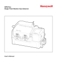
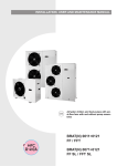
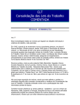
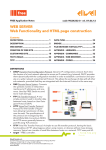
AIR CONDITIONING
Compact controller for central units
msk 528
ADDENDUM
Energy Flex addendum msk528
1. INTRODUCTION........................................................... 3
1.1. How to use this manual............................................................................................................................. 3
1.2. Addendum msk 528.................................................................................................................................. 3
1.3. msk 528 Functions...................................................................................................................................... 3
1.4. Disclaimer.................................................................................................................................................... 3
2. WIRING DIAGRAMS.................................................... 4
2.1. Wiring diagrams......................................................................................................................................... 4
2.2. SKP20 Terminal........................................................................................................................................... 4
2.3. SKP20 - Flex network................................................................................................................................. 5
3. PHYSICAL I/O CONFIGURATION................................ 6
3.1. Digital output configuration..................................................................................................................... 6
4. MSK 528 FEATURES..................................................... 8
4.1. Pump-down on start-up and during shutdown (PAR/CP FOLDER).................................................. 8
4.2. EXTERNAL EXCHANGER FANS (PAR/FE FOLDER)...........................................................................10
4.3. Fan control in defrost ...............................................................................................................................10
5. PARAMETERS (PAr)..................................................... 12
5.1. Parameter table/visibility, display folder table and Client table.......................................................12
5.1.1. Parameters / visibility table................................................................................................................................................................... 13
6. ALARMS....................................................................... 14
6.1. Low pressure digital alarms enabling....................................................................................................14
6.2. Digital Alarms table...................................................................................................................................14
6.3. Analogue Alarms table.............................................................................................................................14
6.4. Vacuum alarm.............................................................................................................................................15
Page 2 / 16
Contents
msk 528 Addendum
Energy Flex addendum msk528
1. INTRODUCTION
1.1. How to use this manual
This manual uses the following conventions to highlight certain parts of the text:
Important
Note
Information that users must be aware of to prevent any damage to the system or hazards for
people, devices, data, etc. Users MUST read and take note of these sections.
Indicates further information on the subject concerned that the user should take into account.
A suggestion that could help the user to understand and make better use of the information
Tip
provided.
*, **, °, °°
Provides further specifications on an explanation provided previously.
Provides references to figures, details in figures, parts of the text. Figures are referred to
Fig. 1, 1 - Fig. 1, etc. using an abbreviation in bold (E.g. ‘Fig.’) and a number identifying the reference (E.g. Fig. 1).
For components inside figures, the references are given using a letter or number (E.g. 1 - Fig. 1).
References to parts of the text are given using the number and title of the relative chapters, subchapters, paragraphs and sub-paragraphs and page number.
1.2. Addendum msk 528
This document is an Addendum of Energy Flex User Manual 8MAx0228 msk 464*
and should be used as and Appendix.
All information provided in this paper are relevant to the only specific functionalities of SBA600 MSK 528
All missing information and /or related to both msk 464/528 are available on Energy Flex User Manual
*x= 0 IT, 1 EN, 2 FR, 3 ES, 5 DE
1.3. msk 528 Functions
•
Pump down in startup and shutdown
•
‘vacuum’ alarm
•
‘dynamic’ defrost
Full list of functionalities is available on Energy Flex User Manual
1.4. Disclaimer
This document is the exclusive property of Eliwell Controls srl and may not be reproduced or divulged without the
express authorisation of Eliwell Controls srl.
All possible care has been taken to ensure the accuracy of this document; nevertheless, Eliwell Controls srl cannot
accept liability for any damage resulting from its use.
msk 528 Addendum
Page 3 / 16
Energy Flex addendum msk528
2. WIRING DIAGRAMS
2.1. Wiring diagrams
Please refer to Electrical Connections chapter from Energy Flex msk 464 manual
2.2. SKP20 Terminal
GND +12V LAN
B
L
A
C
K
R
E
D
B
L
U
E
SKP20
Fig. 1 SKP20 Terminal
Page 4 / 16
msk 528 Addendum
Energy Flex addendum msk528
2.3. SKP20 - Flex network
-
5
+ G
6
7
9
8
10
11
5
12
6
7
9
8
10
11
12
R
E
D
RS-485
/S Models
only
B
L
U
E
B
L
A
C
K
SKP 10
RED
BLUE
BLACK
SE646
SC646/C • SC646/C/S
RED
BLUE
RED
BLUE
BLACK
BLACK
4
G 3 5
AO
DI1
DI2
DI3
DI4
DI5
DI6 AO2
Supply
AI1
AI2
AI3
AI4
AI5 GND GND
Supply
4
G 3 5
AO
DI1
DI2
DI3
DI4
DI5
DI6 AO2
Supply
AI1
AI2
AI3
AI4
AI5 GND GND
Supply
BLACK GND
BLACK GND
BLUE SIGNAL
BLUE SIGNAL
RED 12Vdc
RED 12Vdc
BLACK GND
BLACK GND
BLUE SIGNAL
BLUE SIGNAL
RED 12Vdc
RED 12Vdc
LAN max distance 100m
SKW22(L)
SKP22(L)
SKW22/22L
black / GND
blue / signal
red /+12Vdc
Probe
red /+12Vdc
blue / signal
black / GND
LAN
GND +12V LAN
B
L
A
C
K
R
E
D
B
L
U
E
SKP20
Fig. 2 Flex - SKP20 network
SKP20 and SKW22/SKP22 work in ‘echo’ mode. Both can be present in LAN newtwork.
Any change on SKW22/SKP22 has effect on SKP20 display and viceversa.
msk 528 Addendum
Page 5 / 16
Energy Flex addendum msk528
3. PHYSICAL I/O CONFIGURATION
3.1. Digital output configuration
See the section on Electric Connections available on Energy Flex user manual msk 464 for the number and capacity of
relays/open collectors and for information on the symbols used on labels supplied with the device.
• High voltage outputs (relays) are identified as DO1, DO2, DO3, DO4 and DO6
• The low voltage (SELV), open collector output is called DO5
All digital outputs can be configured as outlined in the table below:
Parameter association - output configuration
Value
Range
Description*
CL90
DOL1 digital output
configuration
-53…+53
See Tab. 3
Present in all models
CL91
DOL2 digital output
configuration
-53…+53
See Tab. 3
Present in all models
CL92
DOL3 digital output
configuration
-53…+53
See Tab. 3
Present in all models
CL93
DOL4 digital output
configuration
-53…+53
See Tab. 3
Present in all models
CL94
DOL5 digital output
configuration
-53…+53
See Tab. 3
Present in all models
(Open collector)
CL95
DOL6 digital output
configuration
-53…+53
See Tab. 3
Present in models with 5 relays
CL96
AOL1 digital output
configuration
See Tab. 3
See Table A msk 464 manual–
Analogue Outputs and Models
(Applies if CL71=0, set CL80
appropriately)
CL97
AOL2 digital output
configuration
-53…+53
See Tab. 3
See Table A msk 464 manual–
Analogue Outputs and Models
(Applies if CL72=0, set CL81
appropriately)
CE90
DOE1 digital output
configuration
-53…+53
See Tab. 3
Present in all models
CE91
DOE2 digital output
configuration
-53…+53
See Tab. 3
Present in all models
CE92
DOE3 digital output
configuration
-53…+53
See Tab. 3
Present in all models
CE93
DOE4 digital output
configuration
-53…+53
See Tab. 3
Present in all models
CE94
DOE5 digital output
configuration
-53…+53
See Tab. 3
Present in all models
(Open collector)
CE95
DOE5 digital output
configuration
-53…+53
See Tab. 3
Present in models with 5 relays
CE96
AOE1 digital output
configuration
See Tab. 3
See Table A msk 464 manual–
Analogue Outputs and Models
(Applies if CL71=0, set CL80
appropriately)
Page 6 / 16
-53…+53
-53…+53
msk 528 Addendum
Energy Flex addendum msk528
Value
CE97
Range
AOE2 digital output
configuration
-53…+53
Description*
See Table A msk 464 manual –
Analogue Outputs and Models
(Applies if CL72=0, set CL81
appropriately)
See Tab. 3
Tab. 1 Parameter association - output configuration
*complete value list is available on Flex user manual msk 464
If multiple outputs have been configured to run the same resource, these outputs will be activated in parallel.
Outputs: configuration table
Polarity is defined as indicated below:
Value
Description
+
Positive
Active when contact closed
-
Negative
Active when contact open
Tab. 2 Digital outputs polarity
Valore
Description
Type
±7
Pump-down Valve circuit 1
Digital
±8
Pump-down Valve circuit 2
Digital
Tab. 3 Digital outputs configuration
If multiple outputs have been configured to run the same resource, these outputs will be activated in parallel.
msk 528 Addendum
Page 7 / 16
Energy Flex addendum msk528
4. MSK 528 FEATURES
Energy Flex msk 528 is able to manage pump-down (on two refrigerant circuits).
4.1. Pump-down on start-up and during shutdown (PAR/CP FOLDER)
The pump-down system consists of unloading the evaporator before each stoppage of the last compressor in the
circuit.
To achieve this aim, it is necessary to have a solenoid valve on the liquid line, which is able to completely intercept the
refrigerant.
The solenoid valve is installed before the thermostatic expansion valve and is able to completely stop the flow of
refrigerant.
The solenoid valve is controlled by the Energy Flex, one for each circuit.
msk 528 parameters
Description
range
default
MU
CP33
Pump-down time during shutdown
0...999
0
sec
CP34
Pump-down interruption set-point
-50.0...99.9
2.0
bar
AL43
Low pressure alarm activation time
from analogue input
0 ... 255
10
sec
Tab. 4 Pump Down parameters
msk 464 parameters involved
Description
range
default
MU
St05
Reversal valve switching delay
0 ... 255
3
sec
St06
Reversal valve switching from Heat to Defrost delay
0 ... 255
15
sec
St07
Reversal valve switching from Defrost to Heat delay
0 ... 255
1
sec
AL44
Low pressure alarm regulator setpoint
from analogue input
-500 ... 999
20
bar
AL45
Low pressure alarm regulator hysteresis
from analogue input
1 ... 255
2.0
bar
Tab. 5 msk464 parameters
Enabling
The function is enabled if the parameter CP33 - Pump-down time during shutdown is different from 0
Digital outputs used
• Circuit 1 pump-down valve
• Circuit 2 pump-down valve
appropriately configured.
Before the last compressor in the circuit is shut down, the solenoid valve is activated (closed). The compressor remains
active until the low pressure analogue input in the same circuit doesn’t reach the Setpoint CP34 - Pump-down
interruption set-point.
Page 8 / 16
msk 528 Addendum
Energy Flex addendum msk528
On the other case (analogue input non configured), compressor will remain active until the low pressure digital input
is activated. On both cases the compressor cannot stay ON after maximum time defined by CP33 - Pump-down time
during shutdown.
At the next request compressors of the circuit, the solenoid valve opens and begins the activation of the compressors
when the analog input of low pressure exceeds the value AL44 + AL45. If the analog input is not configured, it starts
the activation when the digital input of low pressure is deactivated. If the analog input of low pressure is already higher
than the specified threshold or, in his absence, if the digital input of low pressure is already off, compressors activation
starts simultaneously to the opening of the valve.
If the analog input does not exceed the specified threshold or, in the second case, if the digital input low pressure
does not turn off, the compressor does not start and the unit produces a low pressure alarm (analog or digital) after a
CP33 time.
Notes:
•
If an alarm is active, the procedure is ignored and the compressors shut down immediately.
•
If the device is OFF, the procedure is ignored and the compressors shut down immediately.
•
If the device is in standby mode, the pump-down during shutdown procedure occurs as normal.
During the pump-down phases, the digital and analogue low pressure alarms are ignored, for further details refer to
the msk464 user manual.
Notes:
If the value of the parameters St05/St06/St07 is different from 0, the pump-down during shutdown procedure does
not occur:
•
when passing from Heat mode to defrost, and on exiting defrost
•
when passing to antifreeze with heat pump
•
when changing mode
The alarms which deactivate the digital outputs Circuit 1 pump-down valve and Circuit 2 pump-down valve are the
same alarms which deactivate the compressors in the given circuit.
Please Note. in the alarms table no distinction is made between compressors and valve in the same circuit.
msk 528 Addendum
Page 9 / 16
Energy Flex addendum msk528
4.2. EXTERNAL EXCHANGER FANS (PAR/FE FOLDER)
4.3. Fan control in defrost
Enable
Parameter
FE00
Description
Value
0=Ventilation disabled
1 =Continuous operation (Always ON)
2 = Operation on call (ON when compressor ON)
External exchanger fan mode selection
Fan activation in defrost mode is useful because pressure at the external exchanger can reach alarm levels if the exchanger is not totally de-iced. To prevent a high pressure alarm in this situation, the fans are run (at minimum speed if
modulating).
The behaviour of the external exchanger fan during defrost is determined by FE11- Enable special open system
intercooler fan on, in which the fans run at maximum speed.
If the machine has two temperature control circuits, the status of the fan is dependent on the defrost condition of its
respective circuit.
On completion of defrosting the fan resumes operation as requested by its controller.
•
•
If FE11 = 0, the fan is forced off throughout defrosting.
If FE11 = 1, the fan is off or on at minimum speed (digital output active) depending on the analogue input configured for control of the fan in defrost and parameter FE12 -External exchanger fan on setpoint in defrost in the
following way:
External
exchanger
fan
Set Point
FE12
ON/Min.
OFF
Probe FE14
FE13
Fig. 3 Fan defrost control graph
Parameter
Description
Notes
FE12
External exchanger fan on setpoint in defrost Set-Point
FE13
External exchanger fan on hysteresis in defrost Hysteresis
Regulation probe
FE14
Page 10 / 16
Select probe for external exchanger fan
regulation in defrost
0 = No probe
1 =External exchanger temperature (circuit 1 and 2)
2 =High pressure input (circuit 1 and 2)
3 =External exchanger pressure (circuit 1 and 2)
msk 528 Addendum
Energy Flex addendum msk528
MSK 528 features : Defrost Fan speed (external exchanger fan)
FE30 - Minimum speed external exchanger fan in Cool
FE32 - Maximum speed external exchanger fan in Cool
Once the unit is reset the first time actually the minimum speed FE30 is currently used.
If the defrost ends for timeout (dF22 - Maximum defrost time) the minimum speed FE30 will be used as well.
If, however, the first defrost ends by reaching the temperature / pressure then in the next defrost the fan speed will be
increased by an amount equal to ¼ of the difference between the two maximum and minimum speed (FE32 - FE30).
In the subsequent defrosting cycles, the fan speed defrost calculation will be:
• Each time the defrost will end up temperature. / Pressure, the speed will be increased by
(FE32 – FE30)/4, up to a maximum corresponding to FE32;
• Each time the defrost will end, however, by duration, the speed will be decreased by
(FE32 – FE30)/4, up to a minimum corresponding to FE30.
This method allows optimum defrosting of the heat exchanger, with the following settings:
• dF22 with the duration you set “ideal” / defrost waiting for complete defrosting
• end of defrost temperature / pressure situation is not common (not standard situation): this would not in fact have
complete defrosting (eg for non-ideal positioning of the end defrost probe).
The described mechanism has the advantage of auto adapt quickly to environmental conditions and, moreover, does
not require the processing of the historical data.
msk 464 parameters involved
Description
range
default
M.U.
dF22
Maximum defrost time
1 ... 255
5
min
FE00
External exchanger fan mode selection
0 ... 2
1
num
FE12
External exchanger fan on setpoint in defrost
-500 ... 999
190
°C/Bar
FE13
External exchanger fan on hysteresis in defrost
1 ... 255
10
°C/Bar
FE14
Select probe for external exchanger fan regulation in defrost
0 ... 3
1
num
FE30
Minimum speed external exchanger fan in Cool
0 ... 100
50
%
FE32
Maxmum speed external exchanger fan in Cool
0 ... 100
100
%
Tab. 6 msk464 parameters
msk 528 Addendum
Page 11 / 16
Energy Flex addendum msk528
5. PARAMETERS (PAr)
The parameters can be set to fully control Energy Flex controller.
The parameters can be modified via:
• Multi Function Key (MFK);
• keys on the SKP20 (SKP10, SKW22) terminal;
• personal computer and Device Manager software.
Both parameters and folder visibility can be controlled (See Folder table). If folder visibility is modified, the new
setting will apply to all parameters in the folder.
Levels of visibility
There are 4 levels of visibility that can be set by assigning appropriate values to each parameter in the folder, only via
serial, software (DeviceManager or other communication SW) or programming key.
The visibility levels are:
value 3 = parameter or folder always visible;
value 2 = manufacturer level; these parameters can only be viewed by enter the manufacturer’s password
(see parameter Ui28) (all parameters specified as always visible, parameters visible at installer level and
manufacturer level will be visible);
• value 1 = installer level; these parameters can only be viewed by enter the installation password (see parameter
Ui27) (all parameters specified as always visible, and parameters visible at installer level will be visible);
• value 0 = parameter or folder NOT visible.
•
•
Parameters and/or folders with a level of visibility other than 3 (password-protected) will be visible only if the correct
password is entered (installer or manufacturer) following this procedure.
Parameters and/or folders with a level of visibility =3 are always visible even without a password: in this case, the
following procedure is not necessary.
5.1. Parameter table/visibility, display folder table and Client table
The tables below list all information required to read, write and decode all accessible resources in the device.
There are 3 tables:
• the parameter table lists all controller configuration parameters saved in the non-volatile memory, including
visibility;
• the folder table lists all parameter folder visibility details;
• the client table includes all I/O and alarm status resources available in the volatile memory of the instrument.
Page 12 / 16
msk 528 Addendum
Energy Flex addendum msk528
5.1.1. Parameters / visibility table
FOLDER
LABEL
ADDR
DATA
SIZE
CP
CP33
17162
BYTE
CP
CP34
17164
BYTE
AL
AL43
50613
BYTE
49618,4
AL
AL58
50637
BYTE
AL
AL59
17870
BYTE
AL
AL60
17882
BYTE
CPL
Y
Y
EXP
VIS PAR
ADDR
RESET
(Y/N)
R/W
DESCRIPTION
RANGE
DEFAULT
M.U.
49538
RW
Pump-down time during shutdown
0...999
0
sec
49538,2
RW
Pump-down interruption set-point
-50.9...99.9
20
bar
Y
RW
Activation time of low pressure alarm
from analog input
0 ... 255
10
sec
49622,2
Y
RW
Activation time of vacuum alarm
from analog input
0 ... 255
10
sec
-1
49622,4
N
RW
Setpoint of vacuum alarm regulator
from analog input
-50.0 ... 99.9
20
bar
-1
49622,6
N
RW
0.1 ... 25.5
20
bar
-1
Tab. 7
msk 528 Addendum
Hysteresis of vacuum alarm regulator
from analog input
Parameters / visibility
Page 13 / 16
Energy Flex addendum msk528
6. ALARMS
Energy Flex performs full installation diagnostics and reports a variety of alarms.
6.1. Low pressure digital alarms enabling
Low pressure digital alarm follows standard rules (see msk 464 user manual)
Moreover you can decide whter to activate it or not during defrost through AL13 - Enable low pressure alarm during defrost
Note. Low pressure digital alarm related to dedicated circuit is not active if Pump-down valve of the relevant circuit is active (valve closed, Pump-down ongoing, and after
CP33 time after deactivation)
6.2. Digital Alarms table
Label
Descrption/Cause*
E005 Circuit 1 digital low pressure alarm
E006 Circuit 2 digital low pressure alarm
Bypass activation
Circuit compressor activated or reversal of 4-way valve*
Circuit compressor activated or reversal of 4-way valve*
Bypass
AL11**
AL11**
*The bypass is activated by the reversal of the 4-way valve only if at least one compressor is on
**if CP33 is ≠ 0 (pump down enabled), bypass AL11 must be ≠ 0 .
6.3. Analogue Alarms table
Alarm
code
E007
E008
Description
Low pressure (analogue)
circuit 1
Low pressure (analogue)
circuit 2
Bypass activation
event
Bypass time
SET
activation
Hysteresis
Automatic
alarm time
No. interventions
time
Control probe
-
-
AL44
AL45
AL43
AL46
High pressure input circuit 1
-
-
AL44
AL45
AL43
AL46
High pressure input circuit 2
E032
“Vacuum” circuit 1
-
-
AL59
AL60
AL58
E033
“Vacuum” circuit 2
-
-
AL59
AL60
AL58
Page 14 / 16
manual
reset
manual
reset
Low pressure input circuit 1
Low pressure input circuit 2
msk 528 Addendum
Energy Flex addendum msk528
6.4. Vacuum alarm
Enabling
An analogue input shall be set as “Low pressure input circuit 1”. (value 23)
For 2 circuit plants an analogue input shall be set as e “Low pressure input circuit 2”. (value 24)
General conditions of operation
Manual reset only.
The alarm is delayed by a time set by AL58 - Activation time of low pressure alarm from analog input, regardless of the compressors from power on (and / or the valve
pump-down deactivation) of the specific circuit.
The activation is associated with the AL59 - Setpoint of vacuum alarm regulator from analog input and AL60 - Hysteresis of vacuum alarm regulator from analog
input.
Vacuum
alarm
Set Point
AL59
ON
OFF
AL60
Low Pressure probe
Fig. 4 Vacuum alarm graph
Notes.
If probe / probes are in error, unit will be blocked.
The vacuum alarm has the same effects of low pressure alarm, exclusively on the corresponding circuit.
Compared to the alarm low pressure, typically this alarm has lower setpoint and acts with different timing.
msk 528 Addendum
Page 15 / 16
Eliwell Controls s.r.l.
Via dell’Industria, 15 • Z.I. Paludi
32010 Pieve d’Alpago (BL) ITALY
Telephone +39 0437 986 111
Facsimile
+39 0437 989 066
www.eliwell.it
Technical Customer Support:
Technical helpline +39 0437 986 300
E-mail:
[email protected]
Sales
Telephone
E-mail:
+39 0437 986 100 (Italy)
+39 0437 986 200 (other countries)
[email protected]
9MA10239 - Energy Flex - EN - 05/13
© Copyright Eliwell Controls s.r.l. 2013 All rights reserved