1
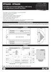
LKD
MANAGEMENT AND MONITORING
Detection and indication of refrigerant leaks
The state-of-the-art LKD gas sensors can
detect the leak of a wide range of gases
(R134a, R404a, NH3, R290, R600a and
CO2).
USER
MANUAL
SUMMARY
1. INTRODUCTION.......................................................................................... 4
1.1 GENERAL DESCRIPTION.......................................................................................................................................4
1.2 TECHNICAL DATA...................................................................................................................................................4
1.3 REGULATIONS.........................................................................................................................................................5
1.4 TEST / FUNCTION INSTRUCTIONS.....................................................................................................................5
1.5 ANNUAL TEST..........................................................................................................................................................5
2. MECHANICAL INSTALLATION.................................................................... 6
2.1 WARNINGS................................................................................................................................................................6
2.2 MOUNTING OF IP41 MODEL................................................................................................................................6
2.3 MOUNTING OF IP66 MODEL................................................................................................................................7
3. INSTALLATION / MAINTENANCE............................................................... 8
3.1 INSTALLATION INSTRUCTIONS............................................................................................................................8
3.2 LOCATION INSTRUCTIONS...................................................................................................................................8
3.2.1 LOCATION OF SENSORS..................................................................................................................................................................8
3.2.2 MACHINERY ROOMS.........................................................................................................................................................................9
3.2.3 REFRIGERATED SPACES....................................................................................................................................................................9
3.2.4 CHILLERS...............................................................................................................................................................................................9
3.2.5 AIR CONDITIONING - DIRECT SYSTEMS VRF/VRV.................................................................................................................... 10
3.3 TYPICAL SETTINGS................................................................................................................................................ 10
3.4 OPERATING INSTRUCTION................................................................................................................................. 10
3.5 FUNCTIONS CUSTOMIZATION.......................................................................................................................... 10
4. CONNECTIONS AND CONFIGURATION.................................................. 11
4.1 STANDARD SEMICONDUCTOR MODEL......................................................................................................... 11
4.2 MODBUS SEMICONDUCTOR MODEL............................................................................................................ 12
4.3 STANDARD INFRARED MODEL......................................................................................................................... 13
4.4 MODBUS INFRARED MODEL............................................................................................................................. 14
5. CONNECTION EXAMPLES........................................................................ 15
5.1 EXAMPLE OF STANDALONE CONNECTION................................................................................................ 15
5.2 EXAMPLE OF NETWORK CONNECTION....................................................................................................... 15
6. FAQ............................................................................................................. 16
7. MODBUS RTU PROTOCOL........................................................................ 17
7.1 MODBUS RTU (REMOTE TERMINAL UNIT) PROTOCOL.............................................................................. 17
7.2 ADDRESS................................................................................................................................................................. 17
7.3 TECHNICAL DATA................................................................................................................................................. 18
7.4 FUNCTION CODES............................................................................................................................................... 18
7.5 REGISTER MAP....................................................................................................................................................... 18
7.5.1 REGISTERS 1000, 1001 E 1002: GAS CONCENTRATION LEVEL........................................................................................... 18
7.5.2 REGISTER 1003: SENSOR FULL SCALE (IN PPM)....................................................................................................................... 19
7.5.3 REGISTER 1004: ALARM SETPOINT (% OF FULL SCALE)........................................................................................................ 19
7.5.4 REGISTER 1005: SENSOR TIMER.................................................................................................................................................. 21
7.5.5 REGISTER 1006: MODBUS ADDRESS.......................................................................................................................................... 21
7.5.6 REGISTER 1007: SOFTWARE VERSION....................................................................................................................................... 21
7.5.7 REGISTER 2000: ALARM SETPOINT (IN PPM)............................................................................................................................. 22
7.5.8 REGISTER 2001: ALARM DELAY.................................................................................................................................................... 23
7.5.11 REGISTER 2002: SOUNDER MUTE DURATION....................................................................................................................... 24
8. WARNING.................................................................................................. 26
8.1 CONDITIONS OF USE......................................................................................................................................... 26
8.2 LIABILITY AND RESIDUAL RISKS....................................................................................................................... 26
8.3 DISCLAIMER.......................................................................................................................................................... 26
1. INTRODUCTION
TECHNICIAN USE ONLY!
This unit must be installed by a suitably qualified technican who will install this unit in accordance with these
instructions and the standards set down in their particular industry/country. Suitably qualified operators of the unit
should be aware of the regulations and standards set down by their industry/country for the operation of this unit.
These notes are only intended as a guide and the manufacturer bears no responsibility for the installation or operation
of this unit. Failure to install and operate the unit in accordance with these instructions and with industry guidelines
may cause serious injury including death and the manufacturer will not be held responsible in this regard.
1.1 GENERAL DESCRIPTION
The state-of-the-art LKD gas sensors can detect the leak of a wide range of gases:
• R134a
• R404a
• NH3
• R290
• R600a
• CO2
Two models available:
• with Semiconductor (SC):
• with Infrared technology (IR):
for refrigerant gases
for CO2
One of the most important features is that they can be used:
• stand-alone, thanks to a relay-activated digital output that can control a buzzer, siren, etc.
• the modbus version can be built into an Eliwell or third-party remote management system (eg. TelevisGo), thanks to an
integrated modbus RS485 (n.b. only model that has it is the CN4 connector).
The main applications are as follows:
• Compressor racks
• LT or MT cold rooms
• Refrigerated cabinets
Detection of an excessive concentration of gas (above the factory-set limit) results in the transmission of an alarm signal to the
supervisor (if connected to the network) and the activation of an on-site acoustic and visual signal.
LKD gas detector ensures a prompt detection of gas leaks thus reducing the risk of machine downtime.
1.2 TECHNICAL DATA
The main technical features of LKD series are:
Model ( ):
IP rating:
Dimensions/Weight:
Power supply:
Power Consumption (at 12V):
Analogue outputs:
Digital outputs:
Internal Buzzer:
Selectable alarm delay (see J5 and J6):
Connections:
Typical operating range:
Temperature range:
Humidity range:
Acoustic alarm(see J3):
Power supply display:
Alarm display:
Fault status:
Fault indication:
Sensor service life:
T50 alarm threshold:
T90 alarm threshold:
Recovery time:
LKD
SEMICONDUCTOR
R134a/R404a/NH3/R290/R600a
INFRARED
CO2
IP41 (MT applications)
and
IP66 (LT applications)
IP41: 86x142x53 - 180 gr.
and
IP66: 175x165x82 - 629 gr.
12/24Vc/a ±20% 50/60 Hz
153mA
136mA
0-5V, 1-5V, 0-10V, 2-10V, 4-20mA
1 relay a 1A/24Vc/a
YES
0, 1, 5, 10 min
1 RS485 for connection to Supervisor Modbus (depending on model)
R134a/R404a: 0...1,000 ppm
R290/R600a: 0...2,000 ppm
CO2: 0...10,000 ppm
NH3: 0...1,000 and 0...10,000 ppm
IP41: -20ºC ... +50ºC
and
IP66: -40ºC ... +50ºC
0 ... 95% (non condensing)
enabled/disabled
Green LED
Red LED
1-5 V configuration:
0.5V
2-10 V configuration:
1V
4-20mA configuration: 2ma
Red LED ON - Green LED OFF
5-8 years
8-10 years
76 secs
25 secs
215 secs
90 secs
600 secs
210 secs
Pag. 4/26
1.3 REGULATIONS
LKD gas sensors are compliant with:
•
•
F-GAS - CE 842/2006 regulation
UNI EN378 standard
provided they are installed by qualified technical personnel and they are checked periodically according to methods and frequency
set by local regulations.
1.4 TEST / FUNCTION INSTRUCTIONS
The LKD is calibrated in the factory and does not require to be calibrated on installation.
After installation the units should be bump tested.
Expose the sensors to test gas:
• using an Eliwell ampoule (NH3, CO2, etc.)
• using a test cylinder (appropriate to the installation)
• open the valve of a cigarette lighter (only for Semiconductor units) without igniting it and hold it over the vent holes on
the upper right side of the LKD. The gas is heavier than air and should fall into the LKD.
This will put the system into alarm:
• The red LED will light showing the system is in alarm.
• The delay will prevent the siren sounding or relay switching for the preset delay, if delay is set.
With a bump test you can see the functions of the sensor:
• the red LED will light
• the relay and sounder will function
• the output selected (for example 0-10 V) will show the gas level.
To test the siren and or relay function, check the delay is set at zero using the header as shown on the installation diagram and expose
to gas as above. You can mute the siren by removing the jumper J3.
After the gas has cleared the red led, siren and relay will automatically reset.
Before testing the sensors on site the LKD must have been powered up and allowed to stabilize.
1.5 ANNUAL TEST
To comply with the requirements of EN378 and the F-GAS regulation sensors must be tested annually.
However local regulations may specify the nature and frequency of this test.
If not the recommended procedure should be followed.
Check local regulations on calibration or testing requirements.
ATTENTION!
After exposure to a substantial gas leak, sensor should be checked and replaced if necessary.
CALIBRATION: Sensor calibration is recommended every three years.
GAS SENSOR: In order to ensure a correct functioning of the unit, a replacement of the gas sensor is
recommended every 6 years.
LKD
Pag. 5/26
2. MECHANICAL INSTALLATION
IMPORTANT!
Always make sure the device is switched OFF before touching connections.
All operations must be carried out by QUALIFIED PERSONNEL.
2.1 WARNINGS
The mechanical mounting varies depending on the version which is being installed (IP41 or IP66).
There are no different mounting instructions for semi-conductor and IR models except for their positioning inside the room to be
monitored, which depends on the specific behaviour of the monitored gas.
2.2 MOUNTING OF IP41 MODEL
The following pictures show dimensions and mounting diagram for model IP41.
8.0
120 mm
141 mm
DIMENSIONS
86 mm
53 mm
MOUNTING
43.0
5 mm max
.5
Ø4
103.5
120 mm
141 mm
7.0
Ø 9.0
Ø4
.5
Ø4
8.0
.5
LKD
25.0
36.0
86 mm
25.0
53 mm
Pag. 6/26
2.3 MOUNTING OF IP66 MODEL
The following pictures show dimensions and mounting diagram for model IP66.
42 mm
123 mm
DIMENSIONS
m
m
75 m
59 mm
50 m
146 mm
175 mm
82 mm
MOUNTING
m
0 m mm
.
9
.0 x -6
Ø 6 ws Ø 5
scre
LKD
42 mm
144 mm
123 mm
122 mm
mm
9.0 6 mm
x
0
Ø 6. s Ø 5
w
e
scr
146 mm
175 mm
82 mm
Pag. 7/26
3. INSTALLATION / MAINTENANCE
3.1 INSTALLATION INSTRUCTIONS
The following steps must be followed:
1. To open the Sensor enclosure: the procedure varies depending on the model:
- IP41 model:
press the fixing device on the top of the box to open it.
To close it, follow the contrary steps; don’t forget to insert the cable clamp in the proper slot on the bottom of the instrument.
- IP66 model:
unscrew the 4 allen screws on the top surface of the instrument.
To close it, follow the contrary steps.
2. Power supply: 12-24 Vc/a, connect power supply cable at positions 0V and +V at connector block CN1.
NOTES: - For AC voltage (a), - For DC voltage (c),
set jumpers J1 = ON and J2 = OFF (See wiring diagram).
set jumpers J1 = OFF and J2 = ON (See wiring diagram).
Default factory setting is direct voltage (c).
Use 2 cores of a 4-core cable, low voltage alarm type (typically 7/0,2 mm2)
3. Output: depending on the type of unit used (Standard or Modbus), it is possible to set the analog output as Voltage Output
(V) or Current Output (mA) by means of the jumpers.
- Standard Model: set jumpers Jx and Jy
(See wiring diagram).
- Modbus Model: set jumpers J7, J8, J9 and J10 (See wiring diagram).
Default factory setting is mA (on Standard model) and always active (on Modbus model).
Connect the other two cores of the 4-core cable used for the power supply to terminal block CN2 in the following positions:
- Current output 4...20mA:
Connect the cores of the cable to terminals 3 (0V) and 5 (I) of CN2.
- Voltage outputs 0...5V, 0...10V, 1...5V and 2...10V:Connect the cores of the cable to terminals 3 (0V) and 4 (V) of CN2.
NOTE: You can common the two zeros and use 3 core cable if preferred.
4. Relay setpoint: The potentiometer P1 sets the trip point for the relay and sounder using the 0-5V scale.
The measurement can be effected between Test Point TP3 (0V) and TP1 (VREF on Standard model and Alarm on Modbus
model). A reading of 2,5 V corresponds to half the range (500 ppm on a scale from 0 to 1000 ppm).
Default factory setting is 50% of the range.
5. Time delay: A time delay for the operation of the relay and sounder can be selected using jumpers J5 and J6.
J5 = OFF,
J5 = ON,
J5 = OFF,
J5 = ON,
J6 = OFF : 0 minutes (no delay)
J6 = OFF : 1 minute
J6 = ON : 5 minutes
J6 = ON : 10 minutes
Default factory setting is J5 = OFF and J6 = OFF.
6. Sounder: The sounder can be disabled using jumper J3.
Default factory setting is option enabled.
NOTE:There is a 5-minute power up delay to allow the sensor to stabilize.
This can be cancelled by momentarily shorting between either of the upper and lower pads of SW1 or SW2.
3.2 LOCATION INSTRUCTIONS
3.2.1 LOCATION OF SENSORS
Sensors must be located within the appropriate wire lengths from the central control unit (if used).
In all cases the sensor supplied is designed for maximum sensitivity to a particular gas (e.g.: R134a, NH3, R290, etc.).
However, in certain circumstances, false alarms may be caused by the occasional presence of sufficiently high concentrations of
other gaseous impurities.
If such a situation is likely to arise installers should check that sensor (s) of suitable cross sensitivity can be supplied.
Examples of situations where such abnormalities may arise include:
• Plant room maintenance activity involving solvent or paint fumes or refrigerant leaks.
• Plant rooms in fruit ripening/storage facilities because of accidental gas migration (bananas - ethylene, apples - carbon
dioxide)
• Heavy localised exhaust fumes (carbon monoxide, dioxide, propane) from engine driven forklifts in confined spaces or close
to sensors.
A response delay may be selected to minimise any problems that might arise.
LKD
Pag. 8/26
3.2.2 MACHINERY ROOMS
There is NO ABSOLUTE RULE in determining the number of sensors and their location.
However a number of simple guidelines will help to make a decision.
Sensors monitor a point as opposed to an area.
ATTENTION!
If the gas leak does not reach the sensor then no alarm will be raised.
Therefore, it is extremely important to carefully select the sensor location.
Also consider ease of access for maintenance.
The size and nature of the site will help to decide which method is the most appropriate to use.
Locations requiring the most protection in a machinery or plant room would be around compressors, pressurised storage vessels,
refrigerant cylinders or storage rooms or pipelines.
Most vulnerable are valves, gauges, flanges, joints (brazed or mechanical), filling or draining connections, etc.
When mechanical or natural ventilation is present mount a sensor in the airflow.
In machinery rooms where there is no discernable or strong airflow then options are:
• Point Detection, where sensors are located as near as possible to the most likely sources of leakage, such as the compressor,
expansion valves, mechanical joints or cable duct trenches.
• Perimeter Detection, where sensors completely surround the area or equipment.
• With heavier than air gases such as halocarbon and hydrocarbon refrigerants such as R404A, propane, and butane sensors
should be located near ground level.
• With lighter than air gas e.g. ammonia, the sensor needs to be located above the equipment to be monitored on a bracket or
high on a wall within 300 mm of, or on the ceiling provided there is no possibility of a thermal layer trapped under the ceiling
preventing gas reaching the sensor.
(NOTE: At very low temperatures, such as in a refrigerated cold store, ammonia gas becomes heavier than air).
• With similar density or miscible gases, such as CO2, sensors should be mounted about head high – say 1.5m.
• Sensors should be positioned a little way back from any high-pressure parts to allow gas clouds to form. Otherwise any leakage
of gas is likely to pass by in a high-speed jet and not be detected by the sensor.
• Make sure that pits, stairwells and trenches are monitored since they may fill with stagnant pockets of gas.
• If a pressure relief vent pipe is fitted to the system, it may be a requirement to mount a sensor to monitor this vent pipe. It should
be positioned about 2 m above the PRV to allow gas clouds to form.
• With racks or chillers pre-fitted with refrigerant sensors, these should be mounted so as to monitor the compressors or if extract
ducts are fitted the airflow in the duct may be monitored.
3.2.3 REFRIGERATED SPACES
In refrigerated spaces sensors should be located in the return airflow to the evaporators on a sidewall, below head height is preferred,
or on the ceiling, not directly in front of an evaporator.
In large rooms with multiple evaporators, sensors should be mounted on the central line between 2 adjacent evaporators, as
turbulence will result in airflows mixing.
3.2.4 CHILLERS
In the case of small water or air-cooled enclosed chiller units mount the sensor so as to monitor airflow to the extract fans.
With larger models also place a sensor inside the enclosure under or adjacent to the compressors.
In the case of outdoor units:
• such as enclosed air-cooled chillers or the outdoor unit for VRV/VRF systems mount the sensor so as to monitor airflow to the
extract fan. With large units also place a sensor inside the enclosure under or adjacent to the compressors.
In the case of non-enclosed outdoor units:
• If there is an enclosed machinery section then locate a sensor there.
• In the case of units with enclosed compressors, mount sensors in the enclosures.
• Where you have protective or acoustic panels mount the sensor low down under the compressors where it is protected by the
panels.
• With air-cooled chillers or air-cooled condensers with non-enclosed condenser sections it is difficult to effectively monitor
leaks in the coil sections. With some designs it will be possible using an airflow sensor to monitor airflow to the start –up fans
in the front or rear sections.
• If there is a possibility of refrigerant leaks into a duct or air-handling unit install a sensor to monitor the airflow.
Weatherproof sensors should be used for unprotected outdoor applications.
LKD
Pag. 9/26
3.2.5 AIR CONDITIONING - DIRECT SYSTEMS VRF/VRV
EN378 states that at least one detector shall be installed in each occupied space being considered.
Also the location of detectors shall be chosen in relation to the refrigerant.
Sensors shall be located where the refrigerant from the leak will collect. In this case refrigerants are heavier than air and detectors
should have their sensors mounted low or other similar Category Class A spaces.
Ceiling or other voids if not sealed are part of the occupied space.
Following a list of things to do and not to do:
DO'S
DON'TS
• mount the in-room sensor at less than the normal heights of Do not mount LKD sensors:
the occupants (between 200-500mm off the floor)
• under reflective surfaces (e.g.: mirrors)
• away from draughts and heat sources like radiators etc.
• inside electrical boards
• avoid sources of steam
• in or near bathrooms.
3.3 TYPICAL SETTINGS
An example of typical setting is:
• Gas:
• Range:
• Alarm setpoint:
refrigerant R404A
0-1000 ppm
500 ppm
For a particular unit please refer to the gas settings shown on the rating plate.
3.4 OPERATING INSTRUCTION
1. On powering up: the sensor will sense the presence of gas after an initial warm-up delay of 5 minutes.
The green LED will flash at 1 second intervals during the warmup (not for MODBUS model).
2. In alarm condition:
• the green LED stays ON;
• the red LED will be ON;
• the buzzer operates (if it has not been disabled using jumper J3 and after a delay if this option has been selected using
jumpers J5 and J6 or using modbus command);
• the relay output activates (after a delay if this option has been selected using jumpers J5 and J6 or using modbus
command);
• the voltage or current output changes proportional to gas concentration.
3. Fault condition:
• the green LED will be OFF;
• the red LED will be ON;
• a voltage or current fault output will activate:
• current fault:
2 mA on the 4-20 mA output;
• voltage fault:
0,5 V on the 1-5 V output and 1,0 V on the 2-10 V output.
3.5 FUNCTIONS CUSTOMIZATION
The functions listed below, need to be agreed with the customer, so that the system will operate as required:
1. Alarm signal delay: applicable to the acoustic alarm (buzzer) and to the relay in order to avoid false alarms.
The delay is set by using jumpers J5 and J6.
J5 = OFF, J6 = OFF : 0 minutes (no delay)
J5 = ON, J6 = OFF : 1 minute
J5 = OFF, J6 = ON : 5 minutes
J5 = ON, J6 = ON : 10 minutes
The default value is 0 minutes.
2. Buzzer: the units have an internal buzzer. It is possible to disable it by removing jumper J3.
The default setting is "buzzer enabled" in compliance to EN378.
3. Output: set the requested analog output (current or voltage)
Gas detectors can activate external systems such as fans or shut down and activate sirens, warning lights or connect to most
BMS, SCADA, or other control systems using one or more outputs.
- 4...20 mA, 0...5 V, 1...5 V, 0...10 V or 2...10 V.
- Relay 1A at 24 Vc or 120 Va
LKD
Pag. 10/26
4. CONNECTIONS AND CONFIGURATION
4.1 STANDARD SEMICONDUCTOR MODEL
CONNECTION DIAGRAM
J6 J5 Jz Jy J3 Jx
J1 J2
TP2
-(0V)
RL-
RL+
VH+
8
RL-
LD1
CN3
RL+
SENSOR
LD2
CN2
TP1
7
6
5
4
3
2
P3
TP3
P2
CN1
P1
1
STANDARD
ELECTRICAL CONNECTIONS and CONFIGURATION
Power Supply
CN1 J1 = ON, J2 = OFF
J1 = OFF, J2 = ON
AC : 1 = a , 2 = a
DC : 1 = 0V , 2 = V+
(12...24 Va)
(12...24 Vc)
Output signals
3 = 0V (0 Volts, ground)
4 = V (The voltage output settings are:
Jx = OFF, Jy = OFF
Voltage output = 0 ... 10V
Jx = ON, Jy = OFF
Voltage output = 0 ... 5V
CN2
Jx = OFF, Jy = ON
Voltage output = 2 ... 10V
Jx = ON, Jy = ON
Voltage output = 1 ... 5V
5 = I (Current output = 4 ... 20 mA)
NOTE: Current output needs to be enabled using Jy (Jy = ON)
Relay
6 = NO
(Normally Open)
CN3
7 = COM (Common)
8 = NC
(Normally Closed)
P1 Alarm Potentiometer
P1 (Alarm):
Adjust alarm setpoint for the sounder and relay.
P2
ZERO Potentiometer
P2 (ZERO):
Adjust the zero level voltage for the output signal.
P3
SPAN Potentiometer
P3 (SPAN):
Adjust output signal span.
Power Supply Jumper (
)
J1, J2 J1 = ON, J2 = OFF : Unit is set for AC power supply
J1 = OFF, J2 = ON : Unit is set for DC power supply
Sounder Jumper (
)
J3 ON = Sounder enabled (Audible alarm if Setpoint reached)
OFF = Sounder disabled (No audible alarms)
Sounder & Relay delay Jumper (
)
J5 = OFF, J6 = OFF : 0 minutes (no delay)
J5, J6 J5 = ON, J6 = OFF : 1 minute
J5 = OFF, J6 = ON : 5 minutes
J5 = ON, J6 = ON : 10 minutes
Jumper Jx and Jy (Voltage output range selection) (
)
Jx = OFF, Jy = OFF
Voltage output setting = 0 ... 10V
Jx, Jy Jx = ON, Jy = OFF
Voltage output setting = 0 ... 5V
Jx = OFF, Jy = ON
Voltage output setting = 2 ... 10V
Jx = ON, Jy = ON
Voltage output setting = 1 ... 5V
Jz
NOT USED
TP1
Setpoint Voltage Test Point TP1 (VREF): Sounder and relay setpoint Voltage.
TP2
Vs Sensor Voltage Test Point TP2 (Vs): Vs sensor voltage.
TP3
0V Test Point TP3 (0V):
LKD
Board ground plane connection.
Pag. 11/26
4.2 MODBUS SEMICONDUCTOR MODEL
CONNECTION DIAGRAM
01
EF 2
3456
01
EF 2
TP1
789A
P1
BCD
J4
789A
3456
SW2
BCD
-(0V)
RL-
VH+
RL+
8
7
6
CN3
LD1
P2
RL+
J10
J9
J8
J7
P4
J5 J6
RL-
J3
SW1
P3
CN4
LD2
SENSOR
11
10
9
CN2
5
4
3
2
TP2 TP3
J1
CN1
1
J2
MODBUS
ELECTRICAL CONNECTIONS and CONFIGURATION
P1
Power Supply
J1 = ON, J2 = OFF
AC : 1 = a , 2 = a
(12...24 Va)
J1 = OFF, J2 = ON
DC : 1 = 0V , 2 = V+ (12...24 Vc)
Output signals
3 = 0V (0 Volts, ground)
4 = V (The voltage output settings are:
J7 = ON, J8, J9, J10 = OFF
Voltage output = 0 ... 5V
J8 = ON, J7, J9, J10 = OFF
Voltage output = 0 ... 10V
J9 = ON, J7, J8, J10 = OFF
Voltage output = 1 ... 5V
J10 = ON, J7, J8, J9 = OFF
Voltage output = 2 ... 10V
5 = I (Current output = 4 ... 20 mA)
Relay
6 = NO
(Normally open)
• 7 = COM (Common)
• 8 = NC
(Normally Closed)
Modbus (RS485)
9 = GND (Ground - Isolated from 0V) • 10 = Tx/Rx+ (Non inverting Modbus Signal) • 11 = Tx/Rx- (Inverting Modbus Signal)
Alarm Potentiometer
P1 (Alarm):
Adjust alarm setpoint for the sounder and relay.
P2
ZERO Potentiometer
P2 (ZERO):
Adjust the zero level voltage for the output signal.
P3
SPAN Potentiometer
P3 (SPAN):
Adjust output signal span.
P4
TP1
4...20 mA Potentiometer
P4 (4-20mA):
Adjust the 4 to 20 mA current output.
Power Supply Jumper (
)
J1 = ON, J2 = OFF : Unit is set for AC power supply
J1 = OFF, J2 = ON : Unit is set for DC power supply
Sounder Jumper (
)
ON = Sounder enabled (Audible alarm if Setpoint reached) • OFF = Sounder disabled (No audible alarms)
Reset Jumper (
)
ON = Stop Unit operation • OFF = Normal functioning
Sounder & Relay delay Jumper (
)
J5 = OFF, J6 = OFF : 0 minutes (no delay)
J5 = ON, J6 = OFF : 1 minute
J5 = OFF, J6 = ON : 5 minutes
J5 = ON, J6 = ON : 10 minutes
Jumper J7, J8, J9 e J10 (Voltage output range selection) (
)
Jumper J7 (Voltage output setting: 0 ... 5V) :
J7 = ON, J8, J9, J10 = OFF
Jumper J8 (Voltage output setting: 0 ... 10V):
J8 = ON, J7, J9, J10 = OFF
Jumper J9 (Voltage output setting: 1 ... 5V) :
J9 = ON, J7, J8, J10 = OFF
Jumper J10 (Voltage output setting: 2 ... 10V): J10 = ON, J7, J8, J9 = OFF
Setpoint Voltage Test Point TP1 (Alarm): Sounder and relay setpoint Voltage.
TP2
Vs Sensor Voltage Test Point TP2 (Vs): Vs sensor voltage.
CN1
CN2
CN3
CN4
J1, J2
J3
J4
J5, J6
J7, J8
J9, J10
TP3
0V Test Point TP3 (0V):
Board ground plane connection.
Address. The valid address has a range of 0 ... 247 and the value is ADR = [SW1 + (SW2x16)].
Example:• SW1=1, SW2=0
ADR= 1 (Valid address)
• SW1=1, SW2=1
ADR= 17 (Valid address)
SW1,
• SW1=7, SW2=F
ADR= 247 (Valid address)
SW2
• SW1=F, SW2=F
ADR= 255 (Reserved)
NOTES: 1) SW1 and SW2 are hexadecimal dial switches.
2) see full Address Table on the Modbus chapter.
LKD
Pag. 12/26
4.3 STANDARD INFRARED MODEL
CONNECTION DIAGRAM
J6 J5 Jz Jy J3 Jx
TP2
J1 J2
TP3
8
SIGNAL
LD1
RX
TX
+V
–V
SENSOR
CN3
TP1
LD2
P1
CN2
7
6
5
4
3
2
CN1
P2
P3
1
STANDARD
ELECTRICAL CONNECTIONS and CONFIGURATION
Power Supply
CN1 J1 = ON, J2 = OFF
J1 = OFF, J2 = ON
AC : 1 = a , 2 = a
DC : 1 = 0V , 2 = V+
(12...24 Va)
(12...24 Vc)
Output signals
3 = 0V (0 Volts, ground)
4 = V (The voltage output settings are:
Jx = OFF, Jy = OFF
Voltage output = 0 ... 10V
Jx = ON, Jy = OFF
Voltage output = 0 ... 5V
CN2
Jx = OFF, Jy = ON
Voltage output = 2 ... 10V
Jx = ON, Jy = ON
Voltage output = 1 ... 5V
5 = I (Current output = 4 ... 20 mA)
NOTE: Current output needs to be enabled using Jy (Jy = ON)
Relay
6 = NO
(Normally Open)
CN3
7 = COM (Common)
8 = NC
(Normally Closed)
P1 Alarm Potentiometer
P1 (Alarm):
Adjust alarm setpoint for the sounder and relay.
P2
ZERO Potentiometer
P2 (ZERO):
Adjust the zero level voltage for the output signal.
P3
SPAN Potentiometer
P3 (SPAN):
Adjust output signal span.
Power Supply Jumper (
)
J1, J2 J1 = ON, J2 = OFF : Unit is set for AC power supply
J1 = OFF, J2 = ON : Unit is set for DC power supply
Sounder Jumper (
)
J3 ON = Sounder enabled (Audible alarm if Setpoint reached)
OFF = Sounder disabled (No audible alarms)
Sounder & Relay delay Jumper (
)
J5 = OFF, J6 = OFF : 0 minutes (no delay)
J5, J6 J5 = ON, J6 = OFF : 1 minute
J5 = OFF, J6 = ON : 5 minutes
J5 = ON, J6 = ON : 10 minutes
Jumper Jx and Jy (Voltage output range selection) (
)
Jx = OFF, Jy = OFF
Voltage output setting = 0 ... 10V
Jx, Jy Jx = ON, Jy = OFF
Voltage output setting = 0 ... 5V
Jx = OFF, Jy = ON
Voltage output setting = 2 ... 10V
Jx = ON, Jy = ON
Voltage output setting = 1 ... 5V
Jz
NOT USED
TP1
Setpoint Voltage Test Point TP1 (VREF): Sounder and relay setpoint Voltage.
TP2
Vs Sensor Voltage Test Point TP2 (Vs): Vs sensor voltage.
TP3
0V Test Point TP3 (0V):
LKD
Board ground plane connection.
Pag. 13/26
4.4 MODBUS INFRARED MODEL
CONNECTION DIAGRAM
01
EF 2
BCD
3456
01
EF 2
TP1
789A
J4
P1
789A
3456
BCD
P2
SW2
J3
SW1
J10
J9
J8
J7
P4
J5 J6
SIGNAL
8
7
6
CN3
LD1
P3
RX
TX
+V
–V
SENSOR
CN4
LD2
11
10
9
CN2
5
4
3
2
TP2
TP3
J1
CN1
1
J2
MODBUS
ELECTRICAL CONNECTIONS and CONFIGURATION
P1
Power Supply
J1 = ON, J2 = OFF
AC : 1 = a , 2 = a
(12...24 Va)
J1 = OFF, J2 = ON
DC : 1 = 0V , 2 = V+ (12...24 Vc)
Output signals
3 = 0V (0 Volts, ground)
4 = V (The voltage output settings are:
J7 = ON, J8, J9, J10 = OFF
Voltage output = 0 ... 5V
J8 = ON, J7, J9, J10 = OFF
Voltage output = 0 ... 10V
J9 = ON, J7, J8, J10 = OFF
Voltage output = 1 ... 5V
J10 = ON, J7, J8, J9 = OFF
Voltage output = 2 ... 10V
5 = I (Current output = 4 ... 20 mA)
Relay
6 = NO
(Normally open)
• 7 = COM (Common)
• 8 = NC
(Normally Closed)
Modbus (RS485)
9 = GND (Ground - Isolated from 0V) • 10 = Tx/Rx+ (Non inverting Modbus Signal) • 11 = Tx/Rx- (Inverting Modbus Signal)
Alarm Potentiometer
P1 (Alarm):
Adjust alarm setpoint for the sounder and relay.
P2
ZERO Potentiometer
P2 (ZERO):
Adjust the zero level voltage for the output signal.
P3
SPAN Potentiometer
P3 (SPAN):
Adjust output signal span.
P4
TP1
4...20 mA Potentiometer
P4 (4-20mA):
Adjust the 4 to 20 mA current output.
Power Supply Jumper (
)
J1 = ON, J2 = OFF : Unit is set for AC power supply
J1 = OFF, J2 = ON : Unit is set for DC power supply
Sounder Jumper (
)
ON = Sounder enabled (Audible alarm if Setpoint reached) • OFF = Sounder disabled (No audible alarms)
Reset Jumper (
)
ON = Stop Unit operation • OFF = Normal functioning
Sounder & Relay delay Jumper (
)
J5 = OFF, J6 = OFF : 0 minutes (no delay)
J5 = ON, J6 = OFF : 1 minute
J5 = OFF, J6 = ON : 5 minutes
J5 = ON, J6 = ON : 10 minutes
Jumper J7, J8, J9 e J10 (Voltage output range selection) (
)
Jumper J7 (Voltage output setting: 0 ... 5V) :
J7 = ON, J8, J9, J10 = OFF
Jumper J8 (Voltage output setting: 0 ... 10V):
J8 = ON, J7, J9, J10 = OFF
Jumper J9 (Voltage output setting: 1 ... 5V) :
J9 = ON, J7, J8, J10 = OFF
Jumper J10 (Voltage output setting: 2 ... 10V): J10 = ON, J7, J8, J9 = OFF
Setpoint Voltage Test Point TP1 (Alarm): Sounder and relay setpoint Voltage.
TP2
Vs Sensor Voltage Test Point TP2 (Vs): Vs sensor voltage.
CN1
CN2
CN3
CN4
J1, J2
J3
J4
J5, J6
J7, J8
J9, J10
TP3
0V Test Point TP3 (0V):
Board ground plane connection.
Address. The valid address has a range of 0 ... 247 and the value is ADR = [SW1 + (SW2x16)].
Example:• SW1=1, SW2=0
ADR= 1 (Valid address)
• SW1=1, SW2=1
ADR= 17 (Valid address)
SW1
• SW1=7, SW2=F
ADR= 247 (Valid address)
SW2
• SW1=F, SW2=F
ADR= 255 (Reserved)
NOTES: 1) SW1 and SW2 are hexadecimal dial switches.
2) see full Address Table on the Modbus chapter.
LKD
Pag. 14/26
5. CONNECTION EXAMPLES
5.1 EXAMPLE OF STANDALONE CONNECTION
INT
RL1
4...20
mA
5.2 EXAMPLE OF NETWORK CONNECTION
RS485
RS232
TelevisGo
LKD
Pag. 15/26
6. FAQ
Here is a list of some of the error signals which might occur:
DEFECT:
Green/Red light on sensor is not lit.
CAUSE:
• power supply.
• possible wiring fault.
• LKD possibly damaged in transit.
RESOLUTION:
• check power supply.
• check wiring.
• install another LKD unit to confirm the presence of a fault.
DEFECT:
Red LED light ON and green LED light OFF to indicate a fault.
CAUSE:
• sensor element may be disconnected from board.
• sensor element has been damaged or has reached end of life.
RESOLUTION:
• check to see sensor element is properly inserted into board.
• change sensor.
DEFECT:
You experience spurious alarms in the absence of a leak.
CAUSE:
Presence of sufficiently high concentrations of other gaseous impurities.
RESOLUTION:
Contact technical support for instructions and support.
LKD
Pag. 16/26
7. MODBUS RTU PROTOCOL
7.1 MODBUS RTU (REMOTE TERMINAL UNIT) PROTOCOL
The CN4 Connector (9 = GND, 10 = Tx/Rx+, 11 = Tx/Rx-) is an RS-485 port for communicating between LKD gas detectors and
the Remote Supervision system in Modbus-RTU protocol.
The meaning of terminals is listed below:
• Tx/Rx+ is the non-inverting data signal
• Tx/Rx- is the inverted data signal
• GND is the board ground plane.
7.2 ADDRESS
There are 256 available selections and the addresses are numbered 0 to 255 inclusive.
Addresses are selected by rotating the hexadecimal dial switches SW1 and SW2.
ATTENTION!
- Values 1 to 247 are valid / usable addresses providing a unique identity for each gas detector.
- Addresses 248 to 255 and address 0 are reserved for implementing specific features.
Modbus data with a zero in the address field is received by all detectors (irrespective of the address selected by the dial switches) to
enable the master device to broadcast simultaneously to all the detectors.
Switch SW1 selects addresses 0 to 15 and switch SW2 multiplies the address by a factor of 16.
ADDRESS
SW1
SW2
0
0
0
RESERVED
1
1
0
Address 1
2
2
0
Address 2
9
9
0
Address 9
10
A
0
Address 10
11
B
0
Address 11
12
C
0
Address 12
13
D
0
Address 13
14
E
0
Address 14
15
F
0
Address 15
16
0
1
Address 16
17
1
1
Address 17
246
6
F
Address 246
247
7
F
Address 247
248
8
F
RESERVED
249
9
F
RESERVED
250
A
F
RESERVED
254
E
F
Selects 9,600 Baud (bits per second)
255
F
F
Selects 19,200 Baud (bits per second)
BCD
01
EF 2
789A
BCD
01
EF 2
3456
SW2
F = 15
3456
SW1
E = 14
SELECTION
As an example, address 254 is reserved for setting the Baud rate to 9,600
bits per second.
To choose a baud rate, select the address and reset the gas detector by
shorting jumper J4 or by cycling the power on and off. The desired Modbus
address (1...247) can subsequently be selected.
X16
789A
ADDRESS 254 = 14 + 15 (x16)
LKD
Pag. 17/26
7.3 TECHNICAL DATA
Baud Rate
9,600
19,200
Start
1
1
bits per second (selectable using SW1 and SW2)
bit
Data
8
8
bit
Parity
1
1
bit (even parity)
Stop
1
1
bit
Retry
500
500
End of message
3.5
3.5
milliseconds (minimum time between retries)
characters
(a silent of 3.5 characters indicates the end of a message, a
new message can begin after this interval)
7.4 FUNCTION CODES
Function codes specify the action to be performed on the data in the registers of the gas detector.
FUNCTION CODE
ACTION
REGISTERS
01
Read Output Digital Status flags
4000
read / writable
02
Read Input Digital Status flags
3000
read only
03
Read Output Analogue Holding Registers
2000
read / writable
04
Read Input Analogue Input Registers
1000
read only
05
Write to Output Digital Status flags
4000
writable
06
Write to Output Analogue Holding Registers
2000
writable
---
read only
43/14
Read Device ID
7.5 REGISTER MAP
The Register Map specifies the details of storage locations (registers and flags) within the detectors.
Analogue Input Registers
(Input Registers are read only)
REGISTER
Function Code 04
DESCRIPTION
RANGE
M.U.
1000
Gas concentration level (% of full scale)
0...100
%
1001
Gas concentration level (parts per million)
0...65,535
ppm
1003
Sensor full scale
0...65,535
ppm
1004
Alarm Setpoint (% of full scale)
1005
Sensor timer
1006
1007
0...100
%
0...65,535
hours
Modbus Address
1...247
---
Software version
100
---
7.5.1 REGISTERS 1000 AND 1001: GAS CONCENTRATION LEVEL
The real time gas concentration is available in different formats:
• Register 1000 maintains the detected concentration in percentage (% of full scale).
• Register 1001 maintains the detected concentration in parts per million (ppm).
For example: a value of 33 represents, in register 1000, 33% of the maximum detectable gas concentration.
LKD
Pag. 18/26
7.5.2 REGISTER 1003: SENSOR FULL SCALE (IN PPM)
The full scale sensor level is the maximum detectable gas concentration for the detector.
This maximum rating is stored in register 1003, so, for the example register 1003, holds the value 1000 to represent 1000 parts per
million (ppm).
Example: GAS CONCENTRATION
%
100%
ppm
1000ppm
Upper
Limit
Alarm
ON
20%
200ppm
Alarm
OFF
Alarm
Setpoint
Time
7.5.3 REGISTER 1004: ALARM SETPOINT (% OF FULL SCALE)
The alarm setpoint is the threshold at which the gas concentration has reached a level to warrant the activation of the red LED alarm
indication, the relay, the sounder and the Alarm flag by setting a 1 in register 3000.
The alarm setpoint can be controlled using the detector hardware by adjusting the potentiometer P1 and monitoring the voltage on test
point TP1 with respect to test point TP3 (0V).
Alternatively a software value can be written into register 2000 to set the alarm level in ppm and override the hardware potentiometer
setting until the software value is reset back to zero, so although register 1004 is a read only register, its value can be modified by writing
to register 2000.
The alarm setpoint register 1004 is measured as a percentage of the full scale so for example, 1.0 Volt measured between test points TP1
and TP3 corresponds to a 20% Alarm Setpoint given that the maximum voltage is 5.0 Volts.
The alarm setpoint register 1004 will contain 20 to represent 20% and this corresponds to a 200 ppm for a detector with a full scale range
of 1000 ppm.
If a delay time is set in 2001 register (valued between 0 and 59 mins), when an alarm occurs:
• the red LED and the Alarm Flag will be immediately activated
• the relay and the sounder will be activated after the delay period is expired
After that the delay period is elapsed, the relay switches ON and the sounder din is audible.
NOTE: The duration of the delay is measured from the instant when the gas concentration reaches the alarm setpoint and the red LED and the alarm flag are activated.
ppm
30% Set Alarm
ON
ALARM
OFF
Alarm Delay
LKD
Pag. 19/26
START
Monitor GAS concentration
Read software Alarm Limit (register) 2000
NO - Reg. 2000 > 0
Use Software SP
Alarm Setpoint
Register 2000 = 0?
YES - Reg. 2000 = 0
Use Hardware SP
Read hardware Alarm Potentiometer P1
Display the Setpoint as a percentage of
full scale in Register 1004
DEACTIVATE
Red LED, Relay,
Sounder and
Alarm Flag = 0
NO
Concentration >
Setpoint?
YES
Set Alarm Flag:
Activate Red LED:
Register 3000 = 1
Register 3000 = 1
Read software Alarm Delay Register 2001.
NO - Reg. 2001 > 0
Use Software Delay
Alarm Delay
Register 2001 = 0?
YES - Reg. 2001 = 0
Use Hardware Delay
Read hardware Delay Jumpers J5 and J6
Wait for the Delay period to expire
ALARM PHASE
Alarm Flag:
Register 3000 = 1
Relay ON:
Register 3001 = 1
Red LED ON:
Register 3003 = 1
Sounder Flag:
Register 4000 = 1
LKD
Pag. 20/26
7.5.4 REGISTER 1005: SENSOR TIMER
The sensor timer register keeps a count of the number of hours the sensor is on.
The register is incremented every hour and after one year the register will exceed 8760 hours and the Test Flag will be set to 1 to indicate
that the detector requires testing.
The Test Flag Register is located at address 4001 and can be cleared to indicate that the sensor and detector have passed the annual test.
New / Tested Sensor
Sensor Timer
Test Flag
(Register 1005) = 1
(Register 4001) = 1
Timer + 1 - every hour
NO
Timer > 8760 hours?
YES
Reset Test request (Register 4001) = 1
NO
Write 0 to
Register 401 to
clear Test Flag = 0
YES
7.5.5 REGISTER 1006: MODBUS ADDRESS
The Modbus address is the value of address set by the hexadecimal switches.
7.5.6 REGISTER 1007: SOFTWARE VERSION
The software version is the revision of firmware operating on the processor of the detector.
Analogue Output Registers
(Output / Registers are readable & writable)
Function code 03 : read
Function code 06 : write
REGISTER
LKD
DESCRIPTION
RANGE
0...65,535
DETAILS
alarm setpoint / threshold in parts per million
2000
Alarm setpoint (ppm)
2001
Alarm delay
0...59
the Alarm Delay is the time in minutes after the gas concentration
exceeds the alarm level and the Alarm Flag Register 300 is set
to 1.
2002
Sounder mute duration
0...59
the Sounder Delay is the time in minutes the sounder
is deactivated for during the alarm phase when the gas
concentration exceeds the alarm set point.
Pag. 21/26
7.5.7 REGISTER 2000: ALARM SETPOINT (IN PPM)
The alarm setpoint register 2000 stores the software setting for the alarm setpoint in parts per million (ppm).
Writing the value zero into this register will enable the hardware potentiometer P1 to determine the alarm setpoint.
If a value greater than zero and less then the full scale sensor limit in ppm is written into register 2000 then the hardware potentiometer
setting is ignored and the value written into register 2000 determines the alarm setpoint.
For example, writing the value 500 into the alarm setpoint register 2000 effectively overrides the hardware alarm set point on the
potentiometer P1 and sets the alarm gas concentration threshold to 500 parts per million and will be displayed as 50 in register 1004 to
represent 50% for a detector with a full scale range of 1000 ppm.
START
Monitor GAS concentration
Read software Alarm Limit (register) 2000
NO
Alarm setpoint
register 2000 = 0?
YES
Read hardware Alarm Potentiometer P1
Display the Setpoint as a percentage of
full scale in Register 1004
Concentration >
Setpoint?
LKD
Pag. 22/26
7.5.8 REGISTER 2001: ALARM DELAY
The Alarm Delay Register 2001 stores the software alarm delay period up to 59 minutes and the jumpers J5 and J6 set the hardware
alarm delay period.
The alarm delay is the duration between the unit detecting a gas concentration above the alarm set point and the activation of the
relay and the sounder.
Only modbus model: If jumpers J5 and/or J6 are present (ON) during the connection of modbus cable (on CN4), the
software value is cleared following a restart whereby the power to the detector is turned off and then turned on again.
Following this restart the delay period is determined by hardware setting of jumpers J5 and J6.
If there are no jumpers on both J5 and J6 the delay period written into the alarm delay register 2001 is used as the delay and is
memorised and reused after a power cycle when the power is turned off and back on.
START
Monitor GAS concentration
Read software Alarm Limit (register) 2000
DEACTIVATE
Red LED, Relay,
Sounder and
Alarm Flag = 0
NO
Concentration >
Setpoint?
YES
Set Alarm Flag:
Activate Red LED:
Register 3000 = 1
Register 3000 = 1
Read software Alarm Delay Register 2001.
NO
0<Register 2001<59
Use Software Delay
Alarm Delay
Register 2001 = 0?
YES
Register 2001 = 0
Use Hardware Delay
Read hardware Delay Jumpers J5 and J6
Wait for the Delay period to expire
ALARM PHASE
Alarm Flag:
Register 3000 = 1
Relay ON:
Register 3001 = 1
Red LED ON:
Register 3003 = 1
Sounder Flag:
Register 4000 = 1
LKD
Pag. 23/26
7.5.11 REGISTER 2002: SOUNDER MUTE DURATION
The sounder mute duration is the time in minutes the sounder is deactivated for during the alarm phase (when the gas concentration has
reached or exceeds the alarm setpoint).
The alarm condition will activate the red LED and set the alarm flag to the value 1.
The relay and the sounder will subsequently activate following any delay period and the alarm flag in register 3000.
The relay flag in register 3001 and the sounder flag in register 4000 will all be set to the value 1 to indicate the active alarm state.
Clearing the Sounder Flag, by writing the value zero into register 4000 will deactivate the sounder for the period defined by the sounder
delay register 2002. The sounder delay is in minutes and the maximum value is 59 so for example if the value in register 2002 is 25, then
the sounder will be disabled for 25 minutes during an alarm condition. After this 25 minute mute period, the sounder will be reactivated
if the detector is still detecting gas concentrations at or above the alarm setpoint, otherwise the sounder will not be reactivated if the gas
concentration has fallen below the alarm setpoint.
START
Monitor GAS concentration
DEACTIVATE
Red LED, Relay,
Alarm Flag and
Sounder Flag = 0
NO
Concentration >
Setpoint?
YES
ALARM PHASE
Concentration > Alarm Setpoint
Red LED, Relay & Sounder = ON
Alarm, Sounder & Relay FLAG: SET = 1
NO
Sounder Flag = 1
Sounder Active
Clear Sounder Flag = 0
(Write 0 to register 4000)
YES
DEACTIVATE Sounder.
Sounder mute (register 4000) = 0
NO
Wait for the Delay
to expire
Sounder Delay
Period expired?
YES
REACTIVATE Sounder.
Sounder mute (register 4000) = 1
LKD
Pag. 24/26
Input Status Flags
(Input Status Flags are read only)
REGISTER DESCRIPTION
Function code 02
RANGE DETAILS
3000
Alarm
0/1
0: Gas concentration is less than the alarm setpoint.
1: Gas concentration is greater or equal to alarm setpoint
3001
Relay
0/1
0: Relay is not active.
1: Relay is active.
3002
Probe Error
0/1
0: Sensor present / in circuit and no open circuit fault detected.
1: Sensor absence or open circuit sensor fault is detected.
3003
Red LED
0/1
0: Red LED is OFF No alarm or fault condition exists.
1: Red LED is ON. Alarm Indication or Fault Indication if green LED is OFF.
3004
Green LED
0/1
0: Green LED is OFF. No power or fault condition if the red LED is ON.
1: Green LED is ON. Power indicator, detector powered ON.
3005
Sensor saturated
0/1
0: The gas level is between zero and the full-scale range.
1: The gas level is outside the bounds of zero and the unit full-scale.
3006
Sensor startup
0/1
0: The unit is operating normally.
1: The unit is starting up.
Output Status Flags
(Output Status Flags are readable & writable)
Function code 01 : read
Function code 05 : write
REGISTER DESCRIPTION
RANGE
DETAILS
4000
Sounder flag
0/1
0: Sounder is OFF.
1: Sounder is ON.
4001
Sensor test required
0/1
0: Sensor does not require testing yet.
1: Sensor ON / operating for more than 1 year and requires testing.
Read Device ID
(Read-only)
Function code 43/14
This function code allows reading the identification and additional information relative to the physical and functional description of
the device.
The implementation of this function follows the specification “MODBUS APPLICATION PROTOCOL SPECIFICATION V1.1b”, section
6.21 as published by the Modbus Organisation.
The following Object IDs have been implemented:
OBJECT ID
TYPE
VALUE
0x00
VendorName
NAME/DESCRIPTION
ASCII String
“INVENSYS”
NOTES
0x01
ProductCode
ASCII String
“00DE_0401”
“00DF_0401”
Semiconductor version
Infrared version
0x02
MajorMinorRevision
ASCII String
“0FA0_0001”
“0FA1_0001”
Semiconductor version
Infrared version
The following “Read Device ID code” options have been implemented:
01: request to get the basic device identification (stream access)
04: request to get one specific identification object (individual access)
LKD
Pag. 25/26
8. WARNING
8.1 CONDITIONS OF USE
Attention!: This product cannot be used in place of a SAFETY device.
It must be used only to signal an alarm.
Sensors monitor a point as opposed to an area. If the gas leak does not reach the sensor then no alarm will be raised.
Therefore, it is extremely important to carefully select the sensor location.
Also consider ease of access for maintenance.
Things to do:
• Install the sensor inside the room at a proper height depending on the refrigerant. Being gases heavier than air, it is normally
recommended to position LKD sensor lower than the average height of people inside the room.
• With heavier than air gases such as halocarbon and hydrocarbon refrigerants such as R404A, propane, and butane sensors
should be located near ground level. With lighter than air gas e.g. ammonia, the sensor needs to be located above the equipment
to be monitored on a bracket or high on a wall within 300 mm of. With similar density or miscible gases, such as CO2, sensors
should be mounted about head high – say 1.5m.
• install sensor away from draughts and heat sources.
Things not to do:
Do not mount LKD sensors:
• under reflective surfaces (e.g.: mirrors)
• inside electrical boards
• in or near bathrooms
8.2 LIABILITY AND RESIDUAL RISKS
Eliwell Controls srl, as a distributor of MURCO Ltd products, declines all liability for damage due to:
• installation/use other than expressly specified and, in particular, in conflict with the safety prescriptions set down in regulations
and/or specified in this document
• tampering with and/or modification of the product
• installation/use on panels that do not comply with statutory laws and regulations
8.3 DISCLAIMER
This document is the exclusive property of ELIWELL CONTROLS SRL and may not be reproduced or circulated without the express
permission of ELIWELL CONTROLS SRL. While all possible care has been taken to ensure the accuracy of this document, ELIWELL
CONTROLS SRL cannot accept liability for any damage resulting from its use. The same applies to any person or company involved
in preparing and editing this document.
ELIWELL CONTROLS SRL reserves the right to make aesthetic or functional changes at any time without notice.
MANUFACTURED BY: Murco Limited - 114a Georges Street Lower, Dun Laoghaire Co Dublin. IRELAND
Eliwell Controls Srl
Via dell' Industria, 15 Z. I. Paludi
32010 Pieve d' Alpago (BL) - Italy
Telephone +39 (0) 437 986 111
Facsimile +39 (0) 437 989 066
Sales:
+39 (0) 437 986 100 (Italy)
+39 (0) 437 986 200 (other countries)
[email protected]
Technical Support:
Technical helpline: +39 (0) 437 986 300
email: [email protected]
www.eliwell.com
9MA10235 - Manuale LKD - 02/13 - EN
© Copyright Eliwell Controls s.r.l. 2013 - All rights reserved