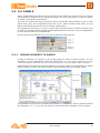
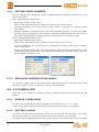
1
Simulation
User Manual
Revision 1.1 - May 2011
Simulation User Manual
Revision 1.1 - 2011-05-20
Published by Eliwell Controls S.r.l.
Via dell’Industria, 15 Z.I. Paludi
32010 Pieve d’Alpago (BL)
© Eliwell Controls S.r.l. 2011.
All Rights Reserved.
II
user manual
Contents
1.Overview
1
2.
Environment components
3
3.
Operating modes
5
3.1
Full simulation
5
3.2
Simplified simulation
5
Using the simulator
7
4.1
Simulation with Application
7
4.2
Simplified simulation with Application
9
4.3
Simulation with UserInterface
9
4.4
Simulation with both Application and UserInterface
11
Program interface
13
5.1
Control panel
13
5.1.1
Manual workspace editing
14
5.2
Target panel
14
5.3
I/O panels
15
5.3.1
Adding elements to panels
15
5.3.2
Editing panel elements
16
5.3.3
Removing elements from panels
16
5.4
I/O panels list
16
5.4.1
Adding a new panel
16
5.4.2
Editing a panel
16
5.4.3
Removing a panel
17
4.
5.
user manual
III
IV
user manual
1. OVERVIEW
The main purpose of Simulation is to execute PLC applications and HMI pages simultaneously in a simulated environment.
Simulation can simulate execution of:
-- PLC applications, IEC 61131-6 (made with Application).
-- HMI pages (made with UserInterface).
The execution can thus take place on the same PC used for the development process, with
the advantage of a faster and simpler testing and debugging phase, because the real final
hardware is not necessary.
user manual
1
2
user manual
2. ENVIRONMENT COMPONENTS
The following paragraph shows you the main components of the simulated environment.
-- Simulation: program that runs the simulator on the PC.
-- Application: PLC development environment connected to the simulator.
-- UserInterface: HMI development environment connected to the simulator.
-- TCP/IP connection: localhost connection between the development environments.
-- Catalog: repository of all target definitions, used by all software components.
-- Simulation targets: Catalog components that define the targets to simulate; these files
have TGSX extension. All targets supporting the simulation have a TGSX file linked in
their PCT.
-- Workspace: user file with WKSX extension that contains all the elements of a working
session of the simulator (I/O panels, source PLC and HMI project, etc.). Each PLC and
HMI project can have multiple simulation workspace files, and the user can manage
them freely.
user manual
3
4
user manual
3. OPERATING MODES
Simulation can work with the two following operating modes.
3.1 FULL SIMULATION
Full simulation is activated when the target simulation file (TGSX) is available in the catalog.
The correct TGSX file is selected automatically by the calling program, depending on the
current active target in the PLC or HMI project.
The full simulation has the following features:
-- simultaneous simulation of both PLC application and HMI pages;
-- availability of the target panel, to have a visual and realistic representation of the target
to run and interact with HMI pages;
-- execution of the simulated application tasks handled by a scheduler that can reproduce
the real target scheduler policy;
-- the simulated target can have some parts implemented in C and/or IEC to implement
the real target behaviour and characteristics, to react to PLC application as the real
target would do;
-- use of the I/O panels, that the user can configure to view and/or modify the simulated
status and I/O variables of the target.
3.2 SIMPLIFIED SIMULATION
Simplified simulation is available only for PLC projects made with Application.
It lets you simulate the application immediately without having a prepared TGSX target
file; in brief it is a simple cyclic execution of all the PLC tasks on the development PC,
without the more advanced and graphical features of the full simulation.
Application will automatically create a temporary TGSX file, to be used with the simulator.
It will be possible to view and/or modify the simulated status and I/O variables of the
target with the I/O panels, as in the full simulation mode.
user manual
5
6
user manual
4. USING THE SIMULATOR
4.1 SIMULATION WITH APPLICATION
Application has a button in the toolbar that lets you activate a simulation session.
Follow the instructions below in order to carry out a simulation session:
1) Write your PLC code with Application.
2) Check the correctness of the code by compiling the project.
3) Activate the simulation with the appropriate button in the toolbar.
4) If there are already running instances of the simulator, Application will ask you if you
want to create a new instance or attach to an existing compatible instance, showing
a list of them; if there are no running instances, a new instance will be automatically
run.
5) You can choose to open a recently used simulator workspace (WKSX) or create a new
one if it is the first simulation session with this PLC project; the last used workspace will be then proposed as the default choice. The list of all used workspaces is saved
inside the PLC project itself.
user manual
7
6) Application will choose the right simulation target file (TGSX) from the Catalog, depending on the target of the current PLC project.
7) Application can now activate the simulation status, that will be similar to the normal
connection to a physical target device, with a different connection status indicator.
While in simulation status, the PLC project will be built for the x86 processor and
the connection will take place using the GDB protocol over TCP/IP on the localhost
(127.0.0.1).
8) Then you can compile and download the code inside the simulated target.
9) In Application you can debug the code as if you were connected the real target
(watchwindow, triggers, breakpoints); it is worth to note that you will be able to debug with all Application debugging features, independently of the real target capabilities.
10) In Simulation you can operate in the target panel (if there is one) to simulate the local I/O.
11) In Simulation you can operate with the I/O panels to change values of the application
parameters.
12) The simulation session is terminated when the user deactivates the simulation mode
inside Application (and the simulator will be automatically closed) or the user manually closes Simulation (in this case the communication in Application will go in the
timeout state, as in the real situation when the physical target is powered off or disconnected).
13) When Simulation is closed everything will be saved inside the current workspace (I/O
panels, window positions, etc.).
14) Application will save the list of recently used workspaces inside the PLC project for
further use.
8
user manual
4.2 SIMPLIFIED SIMULATION WITH APPLICATION
The simplified simulation is almost identical to the full simulation, except for the following
points:
6) Because the TGSX file is not available in the Catalog, Application will self-generate a
temporary one by examining the PLC project and its TGT and IMG files, and pass it
to the simulator.
10) The target panel will not be available, you can interact with I/O panels and/or watchwindow only.
4.3 SIMULATION WITH USERINTERFACE
UserInterface has a button in the toolbar that lets you activate a simulation session, like
in Application.
Perform the following steps for a simulation session, very similar to Application ones:
1) Write your HMI pages with UserInterface.
2) Check the correctness of the code by compiling the project.
3) Activate the simulation with the appropriate button in the toolbar.
4) If there are already running instances of the simulator, UserInterface will ask you
if you want to create a new instance or attach to an existing compatible instance,
showing a list of them; if there are no running instances, a new instance will be automatically run.
user manual
9
5) The user can choose to open a recently used simulator workspace (WKSX) or create a new one if it is the first simulation session with this HMI project; the last used
workspace will be then proposed as the default choice. The list of all used workspaces
is saved inside the HMI project itself.
6) UserInterface will choose the right simulation target file (TGSX) from the Catalog,
depending on the target of the current HMI project.
7) UserInterface can now activate the simulation status. While in simulation status, the
HMI project will be built for the x86 processor and the connection will take place using
the GDB protocol over TCP/IP on the localhost (127.0.0.1).
8) You can then compile and download the code inside the simulated target.
9) In Simulation you can operate on the target panel and work on the pages with the
mouse and the keyboard, and operate on the local I/O.
10) In Simulation you can operate with the I/O panels to change values of the application
parameters.
11) The simulation session is terminated when the user deactivates the simulation mode
inside UserInterface (and the simulator will be automatically closed) or the user manually closes Simulation (in this case next downloads will go in the timeout state, as in
the real situation when the physical target is powered off or disconnected).
12) When Simulation is closed everything will be saved inside the current workspace (I/O
panels, window positions, etc.).
13) UserInterface will save the list of recently used workspaces inside the HMI project for
further use.
10
user manual
4.4 SIMULATION
WITH
USERINTERFACE
BOTH
APPLICATION
AND
It is possible to use Simulation with a simultaneous connection to both Application and
UserInterface; to do so it is required that the target is the same for both PLC and HMI
projects: in this case the second program will connect to the same instance without running a new simulator.
Otherwise, if the targets are different it will be necessary to run two different simulator
instances, each one connected to a different program (one to Application and one to UserInterface).
When all the connected clients (Application and/or UserInterface) will be disconnected
from the simulator, it will be automatically closed.
user manual
11
12
user manual
5. PROGRAM INTERFACE
Simulation is dialog-based Windows program, that is one or more independent windows
that can be moved and placed on the screen.
The following picture shows you the main windows.
5.1 CONTROL PANEL
This is the main window of the simulator. When you launch the simulator, the control panel
is shown in a “compact” form, with only the 5 main buttons and no menu bar.
When you click the Expand button, it will be expanded to show the Menu bar with the
standard new/load/save/exit commands, a central panel showing the main characteristics of the current workspace, an output window showing execution logs, and the I/O
panels list.
With the control panel you can control and monitor the state of the simulated PLC runtime, choose which other windows to show or hide (and their topmost behaviour), and
manage I/O panels.
user manual
13
5.1.1 MANUAL WORKSPACE EDITING
With the menu command Edit/Edit workspace... you can manually edit your workspace, explicitly by inserting which TGSX file to use by choosing it from disk, which PLC
and HMI projects should be simulated, and eventually a “simulation PLC”.
This is a special type of PLC application used to simulate the behaviour of the real hardware, that shares the same data-blocks of the PLC to simulate to react to its actions as
the real target would do.
Each time the simulator is run, the “simulation PLC” is compiled and downloaded along
with the main application.
5.2 TARGET PANEL
This is a floating window that shows a visual representation of the simulated physical target; its presence and layout is defined inside the target definition file (TGSX).
This window typically has an image of the real target, with some sensible areas that show
simulated inputs or outputs (for example LEDs for digital outputs) and a simulated LCD
graphic display where the HMI pages will be drawn.
The user can interact with this window with the mouse or with the PC keyboard, that
emulates the real device keys.
This window is activated with the proper button in the control panel; you can right-click
on it to open its context menu, by which you can activate the topmost state (it will stay
always above any other window) or close it. Finally, you can drag and move it around the
screen anywhere you want.
14
user manual
5.3 I/O PANELS
These small floating windows lets you monitor and change the values of all the various
I/O and status variables of the simulated target; the only requirement is that the object
to watch is allocated on data-block.
The user can create how many panels he wants, and decide which objects to put on each
panel freely; they are complementary to the target panel, because with them you can
watch and edit the I/Os that are not already visible there.
The I/O panels can be put in topmost mode, that is always above all visible windows; this
is useful for example while debugging with Application at full screen; all the configuration
is then saved inside the workspace file.
See the section I/O panels list to see how to add and delete panels.
5.3.1 ADDING ELEMENTS TO PANELS
To add an element (or “signal”) to an existing panel to watch or edit its value, you can
drag&drop it from Application inside the panel itself. You can drag it from the Target
variables panel, from the Workspace tree or from a Variables grid inside an editor.
Depending on the type of the source variables, an analog (slider or progress bar) or digital
(LED or button) control will be generated, and associated with the original signal.
It is possible to add only PLC variables that reside on a DataBlock, with an explicit address
(for example %MW1.0); you can not add to a panel automatic variables, local or global.
user manual
15
5.3.2 EDITING PANEL ELEMENTS
You can edit the more advanced options of each signal by clicking the small icon on the
left of each name.
For a digital I/O the options are:
-- label to be viewed on the panel;
-- name of the associated source variable, and its index if it is an array;
-- read-only attribute: the control will be a LED (output, read-only) or a button (input,
read-write);
-- selector attribute: it is valid only for read-write variables (buttons), if active the button
will keep its value (pressed or not pressed), otherwise it will keep the new value only as
long as the mouse button is pressed, then it will go back to its previous value.
For an analog I/O the options are:
-- label to be viewed on the panel;
-- name of the associated source variable, and its index if it is an array;
-- read-only attribute: the control will be a progress-bar (output, read-only) or a slider
(input, read-write);
-- minimum and maximum limits: if not set, absolute minimum and maximum limits of the
original data type will be used. The progress and slider will use these limits; they can
be individually activated or not.
5.3.3 REMOVING ELEMENTS FROM PANELS
To remove a signal, click on the small button described above for the editing and then
choose the Remove button to delete it (see the above images).
5.4 I/O PANELS LIST
When the Control panel is expanded, you can manage (add/remove/rename) all the I/O
panels.
5.4.1 ADDING A NEW PANEL
To add a new empty panel click the apposite Add button in the Control panel.
A new empty panel without name will be created and placed next to the button.
5.4.2 EDITING A PANEL
In order to rename the panel select it in the list and click the Rename button; you will be
asked for the name to give to the window, that will be shown in its title bar.
Any panel can be drag around the screen in any place; to temporary hide it you can toggle
16
user manual
the check next to its name in the list.
You can also toggle the topmost button to bring the panels above all other windows (this
is a global setting that applies to all panels).
5.4.3 REMOVING A PANEL
In order to remove a panel select it in the list and click the Remove button; the panel and
all its signals and settings will be permanently removed.
user manual
17