1
Electricity Meters IEC/MID
Industrial and Commercial
ZMD400AT/CT, ZFD400AT/CT
E650 Series 3
User Manual
Date: 26.09.2012
File name: D000030110 E650 ZxD400xT Series 3 User Manual en.docx
© Landis+Gyr
D000030110 en g
2/96
Revision history
Revision history
Version
Date
Comments
a
01.07.2009
First edition
b
15.10.2009
Fig. 4.16 replaced
Referenced documents corrected in section 1.8
Error code F.F 00 00 2x 00 added in section 6.2.2 Error Groups
Various grammatical and language errors corrected throughout the document
c
12.11.2009
Minor formatting and typing errors corrected
d
27.05.2010
Update for firmware version B31
e
27.01.2011
Test mode section and document template updated
Optional red LED added to outputs in section 1.4
Phase angles removed from the ZFD400 column in section 1.5.3
Footnote added after table in section 1.5.3
Reactive energy section modified in section 1.5.4
Summation channels section modified in section 1.5.4
Footnote added in section 1.7.2
Section 3.1 retitled "Housing"
f
05.10.2011
Updated document template. Comment regarding grounding inserted in section
4.1.2. Section 5.3.3 "Index System" simplified and new section 11 "Appendix OBIS
Code" inserted.
g
26.09.2012
Update for firmware version B32. New extension board 326x. New measured
quantities. New events. New integrated terminal cover switch. Updated document
template. Section "Safety" becomes first section. OBIS explanation expanded. New
representation of value change procedure in set mode. Minor text improvements
and corrections of formatting and typing errors.
Nothing in this document shall be construed as a representation or guarantee in respect of the performance, quality or durability of the
specified product. Landis+Gyr accepts no liability whatsoever in respect of the specified product under or in relation to this document.
Subject to change without notice.
© Landis+Gyr
D000030110 en g – E650 Series 3 – ZMD400AT/CT, ZFD400AT/CT – User Manual
Table of contents
3/96
Table of contents
Revision history...................................................................................................................................... 2
Table of contents ................................................................................................................................... 3
About this document .............................................................................................................................. 5
1
Safety ............................................................................................................................................. 6
1.1 Safety information ..................................................................................................................... 6
1.2 Responsibilities ......................................................................................................................... 6
1.3 Safety regulations ..................................................................................................................... 7
1.4 Radio Interference .................................................................................................................... 7
2
Device description........................................................................................................................ 8
2.1 Field of application .................................................................................................................... 8
2.2 Characteristics .......................................................................................................................... 8
2.3 Type designation..................................................................................................................... 10
2.4 Block schematic diagram ........................................................................................................ 11
2.5 Measuring system ................................................................................................................... 14
2.5.1 Input signals ...................................................................................................................... 14
2.5.2 Signal processor ................................................................................................................ 15
2.5.3 Measured quantities .......................................................................................................... 17
2.5.4 Formation of measured quantities ..................................................................................... 19
2.5.5 Summation channels ......................................................................................................... 24
2.6 Data profile.............................................................................................................................. 24
2.6.1 Stored value profile ........................................................................................................... 24
2.6.2 Load profile 1 and load profile 2 (option) ........................................................................... 25
2.6.3 Event log ........................................................................................................................... 25
2.7 Communication ....................................................................................................................... 28
2.7.1 Optical interface ................................................................................................................ 28
2.7.2 Communication units ......................................................................................................... 28
2.8 MAP software tools ................................................................................................................. 30
2.9 Anti-tampering features ........................................................................................................... 31
2.9.1 DC magnet detection ......................................................................................................... 31
2.9.2 Terminal cover detection ................................................................................................... 31
3
Mechanical construction ........................................................................................................... 32
3.1 Housing ................................................................................................................................... 32
3.2 Face plates ............................................................................................................................. 35
3.3 Connections ............................................................................................................................ 36
3.4 Connection diagrams (examples) ........................................................................................... 38
3.5 Dimensions ............................................................................................................................. 42
4
Installation and de-installation .................................................................................................. 43
4.1 Basic information for connecting meter ................................................................................... 43
4.1.1 Connection to low voltage with current transformers......................................................... 43
4.1.2 Connection to medium and high voltage (Aron circuit) ...................................................... 44
4.1.3 Connection to medium and high voltage (three-phase four-wire circuit) ........................... 45
4.2 Mounting the meter ................................................................................................................. 46
4.3 Connecting meter .................................................................................................................... 48
4.3.1 Connecting the R-S485 interface ...................................................................................... 51
4.4 Check of connections .............................................................................................................. 52
4.5 Commissioning, functional check and sealing ........................................................................ 52
4.6 Installation of terminal cover detection .................................................................................... 54
4.7 De-installation ......................................................................................................................... 55
D000030110 en g – E650 Series 3 – ZMD400AT/CT, ZFD400AT/CT – User Manual
© Landis+Gyr
4/96
Table of contents
5
Operation .....................................................................................................................................57
5.1 Operation with auxiliary power supply .....................................................................................57
5.2 Control elements .....................................................................................................................58
5.2.1 Display keys .......................................................................................................................58
5.2.2 Control of display via optical interface................................................................................58
5.2.3 Reset key ...........................................................................................................................59
5.3 Display .....................................................................................................................................60
5.3.1 Introduction ........................................................................................................................60
5.3.2 Basic layout ........................................................................................................................60
5.3.3 Index system ......................................................................................................................61
5.4 Types of display .......................................................................................................................62
5.4.1 Operating display ...............................................................................................................62
5.4.2 Display menu .....................................................................................................................63
5.4.3 Service menu .....................................................................................................................66
5.5 Alert LED .................................................................................................................................67
5.6 Optical test output ....................................................................................................................68
5.7 Data readout ............................................................................................................................69
5.7.1 Readout to IEC 62056-21 ..................................................................................................70
5.7.2 Readout to dlms .................................................................................................................72
5.8 Input of formatted commands ..................................................................................................73
5.9 Set time and date, ID numbers, battery time ...........................................................................74
6
Service .........................................................................................................................................75
6.1 Operating faults .......................................................................................................................75
6.2 Error messages .......................................................................................................................75
6.2.1 Structure of an error message ...........................................................................................76
6.2.2 Error groups .......................................................................................................................77
6.3 Repairing meters .....................................................................................................................82
7
Maintenance ................................................................................................................................83
7.1 Meter testing ............................................................................................................................83
7.1.1 Test mode ..........................................................................................................................83
7.1.2 Measuring times .................................................................................................................84
7.1.3 Optical test output ..............................................................................................................84
7.1.4 Creep test ..........................................................................................................................86
7.1.5 Starting test active part ......................................................................................................86
7.1.6 Starting test reactive part ...................................................................................................86
7.2 Changing the battery ...............................................................................................................87
8
Disposal .......................................................................................................................................89
9
Index .............................................................................................................................................90
Appendix 1
© Landis+Gyr
OBIS code ..................................................................................................................93
D000030110 en g – E650 Series 3 – ZMD400AT/CT, ZFD400AT/CT – User Manual
About this document
5/96
About this document
Range of validity
The present user manual applies to the meters specified on the title page.
Purpose
The user manual contains all the information required for metering applications for the intended purpose. This includes:
Provision of knowledge concerning the characteristics, construction
and function of the meters
Information about potential dangers, their consequences and measures to prevent any danger
Details about the performance of all activities throughout the service
life of the meters (parameterisation, installation, commissioning, operation, maintenance, decommissioning and disposal)
Target group
The content of this user manual is intended for technically qualified personnel of utilities (energy supply companies), responsible for system planning,
installation and commissioning, operation, maintenance, decommissioning
and disposal of meters.
Reference documents
The following documents provide further information related to the subject
of this document:
Conventions
D000030106 "E650 ZxD400xT Series 3 Technical Data"
D000030112 "E650 ZxD Series 3 Functional Description"
The structure and significance of meter type designations are described in
section 2.3 "Type designation". The following conventions are employed in
this user manual for representing type designations:
The lower case letter "x" can be used as an unknown to indicate different versions (e.g. ZxD400 for the ZMD400 and ZFD400 meters or
ZMD410xT for the ZMD410AT and ZMD410CT meters).
The digit pair "00" can be used to indicate accuracy data (e.g. ZxD400
for the ZxD405 and ZxD410 meters).
The abbreviated type designation ZMD or ZFD meters can be used
when all three-phase four-wire meters or three-phase three-wire
meters are meant.
The following collective terms are also sometimes used instead of the
type designation:
– "Active energy meters" for the ZxD400AT meters
– "Combi-meters" for the ZxD400CT meters
D000030110 en g – E650 Series 3 – ZMD400AT/CT, ZFD400AT/CT – User Manual
© Landis+Gyr
6/96
1
Safety
Safety
This section describes the safety information used in this manual, outlines
the responsibilities and lists the safety regulations to be observed.
1.1
Safety information
The following symbols are used to draw your attention to the relevant
danger level, i.e. the severity and probability of any danger, in the individual
sections of this document.
Warning
Used to indicate a dangerous situation that could cause bodily injury or
death.
Caution
Used to indicate a situation/ action that could result in material damage or
loss of data.
Note
Used to indicate general guidelines and other useful information.
In addition to the danger level, safety information also describes the type
and source of the danger, its possible consequences and measures for
avoiding the danger.
1.2
Responsibilities
The owner of the meters – usually the utility company – is responsible for
ensuring that all persons working with meters:
Have read and understood the relevant sections of the user manual.
Are appropriately qualified for the work to be performed.
Strictly observe the safety regulations (laid down in section 1.3) and
the operating instructions as specified in the individual sections.
In particular, the owner of the meters bears responsibility for the protection
of persons, prevention of material damage and the training of personnel.
For this purpose, Landis+Gyr provides training on a variety of products and
solutions. Please contact your local Landis+Gyr representative if interested.
© Landis+Gyr
D000030110 en g – E650 Series 3 – ZMD400AT/CT, ZFD400AT/CT – User Manual
Safety
1.3
7/96
Safety regulations
The following safety regulations must be observed at all times:
1.4
The meter connections must be disconnected from all voltage sources
during installation or when opening.
Contact with live parts can be fatal. The relevant supply fuses should,
therefore, be removed and kept in a safe place until the work is completed so that other persons cannot replace them unnoticed.
Local safety regulations must be observed. Only technically qualified
and appropriately trained personnel are authorised to install the
meters.
Only appropriate tools shall be used for the job. This means, e.g. that
the screwdriver must be of the correct size for the screws, and the
handle of the screwdriver must be insulated.
Secondary circuits of current transformers must be short-circuited (at
the test terminal block) without fail before opening. The high voltage
produced by an interrupted current transformer circuit is dangerous to
life and destroys the transformer.
Transformers in medium or high voltage systems must be earthed on
one side or at the neutral point on the secondary side. Otherwise they
can be statically charged to a voltage which exceeds the insulation
strength of the meter and is also dangerous to life.
The meters must be held securely during installation. They can cause
injuries if dropped.
Meters that have been dropped must not be installed, even if no damage is apparent, but must be returned to the service and repair department (or the manufacturer) for testing. Internal damage may result in
malfunctions or short-circuits.
The meters must never be cleaned under running water or with compressed air. Water ingress can cause short-circuits.
Radio Interference
Possible radio interference in residential environments
This meter is normally a class B product. In combination with some communication modules it can become a Class A product. In a domestic environment, this may then cause radio interference, in which case the user may
be required to take adequate measures.
D000030110 en g – E650 Series 3 – ZMD400AT/CT, ZFD400AT/CT – User Manual
© Landis+Gyr
8/96
2
Device description
Device description
This section provides you with a brief overview of the design and function of
the ZxD400xT meters.
2.1
Field of application
ZxD400xT meters can be used for transformer connection at all three voltage levels, namely on low, medium and high voltage. They are primarily
used by medium and large consumers and in the field of energy generation
and exchange.
The ZMD400xT meter is especially suitable for applications at the low voltage level, while the ZFD400xT meter is generally used more at the medium
and high voltage levels.
ZxD400xT meters have a comprehensive tariff structure. This extends from
seasonal tariffs to multiple energy and demand tariff rates.
The ZMD400xT and ZFD400xT meters are designed for connection to current transformers with 5 A or 1 A rated current or as a special version for
both applications (5//1).
The ZMD400CT and ZFD400CT combi-meters record active and reactive
energy consumption, the ZMD400AT and ZFD400AT active energy meters
only the active energy in three-phase four-wire or three-phase three-wire
networks (low, medium and high voltage) and from this determine the required electrical measured quantities. For this purpose they are connected
to the measuring point via current transformers and possibly also voltage
transformers:
Low voltage: ZMD400xT with current transformers
Medium voltage: ZFD400xT (sometimes also ZMD400xT) with current
and voltage transformers
High voltage: ZMD400xT (sometimes also ZFD400xT) with current
and voltage transformers
The data determined are displayed (LCD) and are also available at the optical interface for data acquisition, with an appropriate communication unit
also as required via CS, RS232, RS485, modem, etc.
When equipped with transmitting contacts, the meters can also be used as
transmitting meters for telemetering. The tariff rates can be controlled internally or externally.
With a communication unit, the meters can also be used for recording
counter pulses for other physical media (e.g. water or gas volumes).
2.2
Characteristics
ZxD400xT meters have the following basic characteristics:
© Landis+Gyr
Recording of active, reactive and apparent energy in all four quadrants
(ZxD400CT) or recording of imported and exported active energy
(ZxD 400AT)
Tariff system with energy and demand tariff rates, stored values, load
profiles etc.
Extended functions such as monitoring functions, sliding maximum
demand, etc. (for ZxD400CT additionally power factor cosφ)
D000030110 en g – E650 Series 3 – ZMD400AT/CT, ZFD400AT/CT – User Manual
Device description
9/96
Tariff control
– External
- via control inputs (ZxD400xT21 and ZxD400xT41)
- via communication interfaces using formatted commands
– Internal
- by integral time switch (ZxD400xT24 and ZxD400xT44)
- by event signals based on monitored values, such as voltage,
current, demand etc.
Display of data on a liquid crystal display (LCD)
Active and reactive power per phase and true RMS values of voltages
and currents by means of digital signal processing (DSP) chips
Accuracy: Compliance with IEC class 1 or 0.5 S and with MID accuracy class B or C for active energy consumption (ZxD400xT) and IEC
class 1 for reactive energy (ZxD400CT).
Exception: ZxD402CT – IEC class 0.2S for active energy and IEC
class 0.5 for reactive energy.
Flexible measuring system through parameterisation (definition of
different variables by software)
Correct measurement even with failure of individual phases or when
used in two- or single-phase networks
Wide range of measurement from starting current to maximum current
Optical interface according to IEC 62056-21 and dlms
– for direct readout of meter data
– for service functions of the meter, extension board and communication unit (e.g. parameterisation)
Inputs for recording fixed valency pulses (communication unit)
Output contacts (solid-state relays) for fixed valency pulses, control
signals and status messages
Output contacts (relays) for control and status messages
Input contact for alarm monitoring and sending SMS messages, if
suitable optional communication unit selected
Installation aids
– Indication of phase voltages, phase angles, rotating field and
direction of energy
Storage of event information, e.g. voltage failures, exceeding of thresholds or error messages. Event information can be read out via the
available interfaces. Important events can be communicated to the
energy supply company as operational messages (sending of SMS
messages, control of an arrow in the display, drive for an output contact, etc.).
Interfaces such as CS, RS232, RS485, modem, etc. for remote transmission of data (communication unit)
Auxiliary power supply for communication with the meter if no measuring voltage is present
D000030110 en g – E650 Series 3 – ZMD400AT/CT, ZFD400AT/CT – User Manual
© Landis+Gyr
10/96
2.3
Device description
Type designation
ZMD
4
10
C
T
44
4207
S3
Network type
ZFD
ZMD
3-phase 3 wire network (F-circuit)
3-phase 4 wire network (M-circuit)
Connection type
4
Transformer operated
Accuracy class
10
05
02
Active energy class 1 (IEC), B (MID)
Active energy class 0.5 (IEC), C (MID)
Active energy class 0.2 (IEC)
Measured quantities
C
A
Active and reactive energy
Active energy
Construction
T
With exchangeable communication units
Tariffication
21
24
41
44
Energy rates, external rate control via control inputs
Energy rates, internal rate control via time switch
(additionally possible via control inputs)
Energy and demand rates, external rate control via control inputs
Energy and demand rates, internal rate control via time switch
(additionally possible via control inputs)
All versions with 3 control inputs and 2 output contacts
Additional functions
000x
060x
240x
326x
420x
045x
046x
No extension board
6 outputs
2 control inputs, 4 outputs
3 control inputs. 2 relays outputs, auxiliary power supply 12–24 VDC
4 control inputs, 2 outputs
4 outputs, auxiliary power supply 100–240 VAC/VDC
4 outputs, auxiliary power supply 12–24 VDC
xxx0
xxx2
xxx7
xxx9
No additional functions
DC-magnet-detection
Load profile
DC-magnet-detection and load profile (integrated terminal cover switch option only available
in this configuration)
Series 3
As the communication unit is a device on its own, it is not part of the meter’s
type designation. The customer can exchange it at any time without opening
the certification seal. Each communication unit has its own user manual.
Series designation
The hardware version is defined with a series designation. The first hardware generation (Series 1) does not have a series designation.
The type designation on the nameplate ends with the series designation S2
for the 2nd hardware generation (Series 2). An attached suffix points out
© Landis+Gyr
D000030110 en g – E650 Series 3 – ZMD400AT/CT, ZFD400AT/CT – User Manual
Device description
11/96
that the meter is equipped with certain non-standard features, e.g. S2s
represents a Series 2 meter with symmetrical terminal layout.
S3 represents the newest hardware generation.
Firmware version
Class 0.2
2.4
The meter’s firmware version, which determines certain meter characteristics, can be displayed on the LCD e.g. as part of the rolling display (depending on parameterisation) and can be read out in the following two ways:
meter data readout (depending on parameterisation)
meter identification readout (see section 5.7 "Data readout")
Some executions of ZMD400CT/CR meters are available with accuracy
class 0.2S. These meters fulfill the IEC accuracy class 0.2S for active energy and class 0.5 for reactive energy. For details see the corresponding
datasheet.
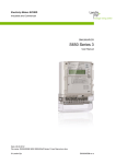
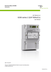
Block schematic diagram
This section provides an overview of the function of ZxD400xT meters
based on a block schematic diagram.
Figure 1
Block schematic diagram ZMD400xT
The ZxD400AT active energy meters record the imported and exported
active energy consumption, while the ZxD400CT combi-meters record the
active and reactive energy consumption in all four quadrants.
The ZxD400xT meters can be fitted with modular communication interfaces
in a communication unit, which can be exchanged or used in the field as
required.
Inputs
The main meter inputs are:
Connections of phase voltages (U1, U2, U3), phase currents (I1, I2, I3)
and neutral conductor N
– for processing in the measuring system
– for the three-phase power supply to the meter and voltage monitor
Control inputs Ut (3 fixed, plus up to 4 others on extension board) for:
– Changeover of energy and demand tariff rates
– Resetting
D000030110 en g – E650 Series 3 – ZMD400AT/CT, ZFD400AT/CT – User Manual
© Landis+Gyr
12/96
Device description
– Demand inhibition
– Synchronizing
Opto-couplers protect the internal circuitry from interference, which
could otherwise enter via the control inputs.
Keys
– for display control (display keys, optical interface)
– for resetting or service functions (reset key)
Outputs
Pulse inputs for connection of external pulse transmitters (only for
meters equipped with a communication unit)
The meter has the following outputs:
LCD display with display keys for local reading of billing data (single 8digit display with additional information, such as energy direction, type
of energy, presence of phase voltages and identification number)
Optical test outputs (red, 1 in active energy meters, 2 in combi-meters)
Optional alert LED (red) to indicate alerts on the front face of the meter
Static relay with freely parameterised signal assignment (2 fixed, plus
up to 6 others on the extension board)
Relay outputs with limited parameterised signal assignment due to
limited life expectancy (up to 2 on the extension board)
Optical interface for automatic local data acquisition by a suitable
acquisition unit (handheld terminal)
Communication interfaces of various kinds in the communication unit
(see also section 2.7 "Communication")
Measuring system
The input circuits (voltage dividers and current transformers) record voltage
and current in the individual phases. Analogue-digital converters digitise
these values and feed them as instantaneous digital values via calibration
stages to a signal processor.
Signal processing
The signal processor determines the following measured quantities from
the instantaneous digital values of voltage and current for each phase and
forms their mean value over one second:
© Landis+Gyr
Active power per phase
Reactive power per phase (combi-meters ZxD400CT only)
Phase voltages
Phase currents
Network (mains) frequency
Phase angles
D000030110 en g – E650 Series 3 – ZMD400AT/CT, ZFD400AT/CT – User Manual
Device description
Signal utilisation
Tariff control
Data preparation for
billing
Memory
13/96
For signal utilisation in the various registers, the microprocessor scans the
measured quantities every second to determine the following values:
Active energy (sum and individual phases, separated according to energy direction, if required in the combi-meters ZxD400CT also
assigned to the 4 quadrants)
Reactive energy (only for combi-meters ZxD400CT, sum and individual
phases, separated according to energy direction, assigned to the 4
quadrants)
Apparent energy (only for combi-meters ZxD400CT, sum and
individual phases, separated according to energy direction)
Power factor cosφ (only for combi-meters ZxD400CT, individual
phases and mean value)
Phase voltages
Phase currents and neutral current
Active and reactive power
Direction of rotating field
Total harmonic distortions of active energy, voltage and current
Energy losses (line losses and transformer losses)
Tariff control is performed:
Externally via control inputs (3 fixed, plus up to 4 others on the extension board)
Externally via communication interfaces using formatted commands
Internally by time switch and calendar clock
By event signals based on threshold values of the monitoring functions
The following registers are available for evaluation of the individual
measured values:
32 for energy rates
27 for total energy
10 for running mean demand values
24 for demand rates
2 for power factors cosφ (combi-meters ZxD400CT only)
up to 41 diagnostic registers
others for values of voltage and current, network frequency and phase
angles
A non-volatile flash memory serves to record data profiles and also contains the configuration and parameterisation data of the meter and secures
the billing data against loss due to voltage failures.
D000030110 en g – E650 Series 3 – ZMD400AT/CT, ZFD400AT/CT – User Manual
© Landis+Gyr
14/96
Device description
Power supply
The supply voltages for the meter electronics are obtained from the threephase network, whereby the phase voltage can vary over the entire voltage
range without the supply voltage having to be adjusted. A voltage monitor
ensures correct operation and reliable data recovery in the event of a
power failure and correct restarting when the voltage is restored.
Auxiliary power
supply
For medium or high-voltage applications in particular, the measuring voltage can be switched off. Since the meter normally obtains its supply from
the measuring voltage, it is also switched off and cannot be read. The auxiliary power supply connected in parallel with the normal power supply ensures operation of the meter free from interruption, so that it can be read at
any time. The auxiliary power supply is situated on an extension board.
Extension board
The extension board is fitted inside the meter and is secured by the certification seals. It cannot be exchanged. It can have the following components:
Communication unit
2.5
up to 4 control inputs in combination with
up to 6 output contacts (solid-state relays)
up to 2 relays outputs
an auxiliary power supply
The communication unit for fitting only in the ZxD400xT meters is a complete unit in its own case. If present, it is situated behind the front door, and
is therefore secured by a utility seal and can be exchanged or inserted in
the field if necessary. It contains:
Communication interfaces as required for remote readout of the meter
(e.g. CS, RS232, RS485, modem)
2 signal inputs (S0 interfaces) for processing external pulse transmitters
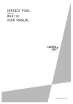
Measuring system
Figure 2
2.5.1
Block schematic diagram of measuring system
Input signals
The meter has the analogue current values I1, I2 and I3 and analogue voltage values U1, U2 and U3 available as input signals.
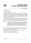
ZMD400xT
Figure 3
© Landis+Gyr
Type of measurement ZMD400xT
D000030110 en g – E650 Series 3 – ZMD400AT/CT, ZFD400AT/CT – User Manual
Device description
15/96
Since the ZMD400xT measures the individual phases mutually independently with one measuring element each, it can record the sum of the three
phases, the individual phases themselves, the phase angle between voltage and current as well as the angle between voltages U1–U2 and U1–U3.
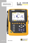
ZFD400xT
Figure 4
Type of measurement ZFD400xT
The ZFD400xT with Aron circuit records with its two measuring elements
the phase currents I1 or I3, together with the corresponding voltage U12 or
U32. It cannot therefore construct any actual single-phase values. In addition, the phase angles between voltage and current always have an additional angle of 30° and are therefore not representative.
Voltage input
High resistance voltage dividers reduce the voltages U1, U2 and U3 (58 to
240 V) applied to the meter to a proportionate amount of a few mV (UU) for
further processing.
Current input
Internal current transformers reduce the input currents I1, I2 and I3 to the
meter (0 to 10 A) for further processing. The secondary currents of these
current transformers develop voltages proportional to the input currents
across resistors, also of a few mV (UI).
2.5.2
Signal processor
Figure 5
Principle of signal processor
ZxD400AT active energy meters do not measure reactive energy.
Digitizing
The analogue signals Ux and Ix are digitised in Sigma-Delta converters
(analogue-digital converters with highest resolution) with a sample rate of
1.6 kHz and then filtered. A following calibration stage compensates for the
natural errors of the voltage divider or current transformer, so that no further adjustment is necessary in the subsequent processing.
Calibrated digital instantaneous values of voltage (u) and current (i) for all
three phases are then available as intermediate values for the formation of
the required values in the signal processor.
D000030110 en g – E650 Series 3 – ZMD400AT/CT, ZFD400AT/CT – User Manual
© Landis+Gyr
16/96
Calculation of active
power
Device description
The instantaneous value of active power p is produced by multiplying the
instantaneous values of voltage u and current i (the active component corresponds to the product of voltage component with the current component
parallel to the voltage). Thereby the harmonics up to 1 kHz are measured
correctly.
IQ
I
Calculation per phase of
P = U . I . cos
IP
Figure 6
Instantaneous power
with sign
U
Active power calculation
If the meter is parameterised to calculate instantaneous power as signed
values, the following values of power are available:
Active P:
+ in QI and QIV, - in QII and QIII
Reactive P:
+ in QI and QII, - in QIII and QIV
Calculation of reactive There are two possibilities to calculate the instantaneous value of reactive
power (ZxD400Cx combi-meters only):
power
Measured:
For the instantaneous value of reactive power q the instantaneous value of
voltage u must be rotated by 90° before multiplication (the reactive
component is the product of the voltage component with the current
component vertical to the voltage). Thereby no harmonics are measured
since only the fundamental wave is rotated through 90°.
IQ
I
Calculation per phase of
Q = U . I . sin
IP
Figure 7
U
Reactive power calculation (method: measured)
Calculated vectorial (not recommended):
The instantaneous value of reactive power is calculated using the values of
active power and apparent power.
The reactive power is the square root of the square value of apparent
power minus the square value of active power. This method includes the
harmonics.
URMS, IRMS calculation
© Landis+Gyr
The square values of voltage and current are obtained by multiplying the
instantaneous values of voltage and current by themselves. From these
values the signal processor forms the corresponding single-phase RMS
values URMS and IRMS.
D000030110 en g – E650 Series 3 – ZMD400AT/CT, ZFD400AT/CT – User Manual
Device description
Time measurement
17/96
The network frequency can be calculated from the time measured between
two zero passages (change from negative to positive value of voltage U1).
The times between zero passage of the phase voltage U1 and those of the
other phase voltages U2 and U3 serves to determine the phase angle between the voltages and of the rotating field.
U1
U2
Time measurement
for rotating field,
frequency, phase angle
U3
1 : T U1-U2
2 : T U1-U3
1
Figure 8
2
3 : TU1-U1 (fn)
3
Time measurement
The phase angle between voltage and current is determined by the times
between zero passage of the phase voltage U1 and those of the phase currents I1, I2 and I3.
Mean value formation
2.5.3
For further processing of the individual signal the signal processor generates mean values over one second, which the following microprocessor
scans at intervals of one second.
Measured quantities
Measured quantity
ZMD400
ZFD400
Active energy in quadrant I
A (QI)
Sum / Phases
Sum
Active energy in quadrant II
A (QII)
Sum / Phases
Sum
Active energy in quadrant III
A (QIII)
Sum / Phases
Sum
Active energy in quadrant IV
A (QIV)
Sum / Phases
Sum
Active energy import
+A (QI+QIV)
Sum / Phases
Sum
Active energy export
–A (QII+QIII)
Sum / Phases
Sum
Active energy, absolute value
+A+-A
Sum / Phases
Sum
Active energy, absolute value
+A--A
Sum / Phases
Sum
Active energy import summation
Σ +A
Sum
Sum
Acitve energy export summation
Σ -A
Sum
Sum
Active energy by single quantity
Σ ALx
Sum
Sum
Reactive energy in quadrant I
R (QI)
Sum / Phases
Sum
Reactive energy in quadrant II
R (QII)
Sum / Phases
Sum
Reactive energy in quadrant III
R (QIII)
Sum / Phases
Sum
Reactive energy in quadrant IV
R (QIV)
Sum / Phases
Sum
Reactive energy import
+R (QI+QII)
Sum / Phases
Sum
Reactive energy export
–R (QIII+QIV) Sum / Phases
Sum
Reactive energy import
+R (QI+QIV)
Sum / Phases
Sum
Reactive energy export
–R (QII+QIII)
Sum / Phases
Sum
Reactive energy, combined
R (QI+QIII)
Sum / Phases
Sum
Reactive energy, combined
R (QII+QIV)
Sum / Phases
Sum
Reactive energy, absolute value
+R+-R
Sum / Phases
Sum
D000030110 en g – E650 Series 3 – ZMD400AT/CT, ZFD400AT/CT – User Manual
© Landis+Gyr
18/96
Device description
Measured quantity
ZMD400
ZFD400
Sum / Phases
Sum
Reactive energy import summation Σ +R
Sum
Sum
Reacitve energy export summation Σ -R
Sum
Sum
Apparent energy import
+S (QI+QIV)
Sum / Phases
Sum
Apparent energy export
-S (QII+QIII)
Sum / Phases
Sum
Phase voltages (RMS)
U1, U2, U3
U12, U32
Phase currents (RMS)
I1, I2, I3
I1, I3
Reactive energy, absolute value
+R--R
Neutral current
I0
yes
no
Network frequency
fn
yes
yes
Active power
±P
Sum / Phases
Sum
Reactive power
±Q
Sum / Phases
Sum
Phase angle between voltages
U
U1-U2 / U1-U3* no
Phase angle between voltage and
current
U-I
U1-I1, U1-I2,
U1-I3 *
or
U1-I1, U2-I2,
U3-I3
no
Power factor
PF
Sum / Phases
Sum
yes
yes
Direction of rotating field
THD of active energy import
+THDA
Sum
Sum
THD of active energy export
-THDA
Sum
Sum
THD of active energy (percent)
THDA [%]
Sum
Sum
THD of phase voltages (absolute)
THDU
Phase 1, 2, 3
Phase 1, 3
THD of voltage (percent)
THDU [%]
Sum
Sum
THD of phase currents (absolute)
THDI
Phase 1, 2, 3
Phase 1, 3
THD of current (percent)
THDI [%]
Sum
Sum
Line (copper) losses of active
energy
OLA
Sum
Sum
Transformer (iron) losses of active
energy
NLA
Sum
Sum
Voltage square hours
U2h
Sum
Sum
Sum
Sum
Ampere square hours
2
Ih
* Only if U1 is present.
© Landis+Gyr
D000030110 en g – E650 Series 3 – ZMD400AT/CT, ZFD400AT/CT – User Manual
Device description
2.5.4
19/96
Formation of measured quantities
By scanning the mean values of active power P, and in combi-meters also
reactive power Q every second, energy components are produced (Ws or
vars) at fixed intervals (every second) and with varying energy magnitudes
or demand. These energy components are scaled by the microprocessor
corresponding to the meter constant and are then available as measured
quantities for selection of the measured values. The measured values are
fed directly to the following registers to record the energy and the maximum
demand (in combi-meters also of minimum power factor).
Active energy
The active energy in the individual phases ±A1, ±A2 and ±A3 are formed
directly from the mean values of active power P1, P2 and P3.
By summating the mean values of active energy A1, A2 and A3 the microprocessor calculates the total active energy import +A or the total active
energy export -A.
Mean values
per second
Measured quantities
± A1
+A (Import)
±A 2
-A (Export)
±A3
Figure 9
Reactive energy
Total active energy
The reactive energy values of the individual phases ±R1, ±R2 and ±R3 are
obtained in the combi-meters directly from the mean values of reactive
power Q1, Q2 and Q3. The reactive energy can therefore also be
calculated vectorially (see 1.5.2).By summating the mean values of reactive
energy R1, R2 and R3, the microprocessor calculates the total positive
reactive energy +R or the total negative reactive energy -R.
Mean values
per second
Measured quantities
± R1
±R2
±R3
+R
-R
Figure 10 Total reactive energy
The microprocessor can allocate the reactive energy to the 4 quadrants in
the combi-meters from the signs of R and A:
Reactive energy in 1st quadrant: +Ri
Reactive energy in 2nd quadrant: +Rc
Reactive energy in 3rd quadrant: –Ri
Reactive energy in 4th quadrant: –Rc
In the same way it can allocate the reactive energy of the individual phases
to the 4 quadrants.
D000030110 en g – E650 Series 3 – ZMD400AT/CT, ZFD400AT/CT – User Manual
© Landis+Gyr
20/96
Device description
+R
+ kvarh
+ kvarh
+Rc
+Ri
Quadrant II
Quadrant I
Export -A
+A Import
- kWh
Quadrant III
Quadrant IV
-Ri
-Rc
- kvarh
+ kWh
- kvarh
-R
Figure 11 4-quadrant measurement
The quadrants are numbered from top right as 1st quadrant (+A/+Ri) anticlockwise to the 4th quadrant (+A/–Rc) at bottom right.
Apparent energy
The apparent energy is calculated in the combi-meters in two ways:
by vectorial addition of the active and reactive energy of the individual
phases
by multiplying the rms values of voltage and current of the individual
phases
The method of calculation can be parameterised (only one possible in each
case).
Calculation method 1
(vectorial addition)
From the mean values A1, A2 and A3 and R1, R2 and R3 the microprocessor calculates the apparent energy of the individual phases ±S1, ±S2 and
±S3 as well as the total apparent energy ±S.
Mean values
per second
±A1
±A2
±A3
Measured quantities
2
(A1 + A2 + A3) + (R1 + R2 + R3)
2
-S (Export)
±R1
±R2
+S (Import)
±R3
Figure 12 Total apparent energy according to calculation method 1
© Landis+Gyr
Only fundamental wave considered for reactive energy
Only the fundamental wave is considered for the calculation of the reactive
energy share; possible harmonics are not taken into account.
D000030110 en g – E650 Series 3 – ZMD400AT/CT, ZFD400AT/CT – User Manual
Device description
Calculation method 2
(from rms values)
21/96
From the mean values U1rms, U2rms, U3rms and I1rms, I2rms, I3rms the microprocessor calculates by multiplication the apparent power of the individual
phases ±VA1, ±VA2 and ±VA3 and summates these for the total apparent
power ±VA.
Mean values
per second
I1rm s
I1rm s U1 rm s
I2rm s U2 rm s
I3rm s U3 rm s
å
U1rm s
I2rm s
å
U2rm s
I3rm s
å
U3rm s
Measured quantities
+S (Import)
-S (Export)
Figure 13 Total apparent power according to calculation method 2 (ZxD400Cx
combi-meters only)
Harmonics considered for reactive energy
As RMS values are used for the calculation of the apparent energy with calculation method 2, not only the fundamental wave but also the harmonics
are taken into account. Therefore, if harmonics are present, the measured
values are greater than those of calculation method 1.
Summation channels
The values of two measurement quantities (incl. pulse inputs EX1 and EX2)
can be added.
Power factor cosφ
The power factor cosφ is calculated in combi-meters as follows:
The meter uses the method of calculation employed for calculating the
apparent power.
Phase voltages
The rms values of the voltages U1rms, U2rms and U3rms are obtained from
the mean values of the squares of the voltages by extracting the root and
directly from these the phase voltages U1, U2 and U3.
Phase currents
The rms values of the currents I1rms, I2rms and I3rms are obtained from the
mean values of the squares of the currents by extracting the root and directly from these the phase currents I1, I2 and I3.
Neutral current
The signal processor calculates the instantaneous neutral current i0 by
adding the instantaneous phase currents i1, i2 and i3.
i2
i1
i3
i0 = i1 + i2 + i3
(vectorial addition)
i0
Figure 14 Neutral current I0
Network frequency
The signal processor calculates the network frequency fn by forming the
reciprocal from the time tU1-U1 between two zero passages of voltage U1.
D000030110 en g – E650 Series 3 – ZMD400AT/CT, ZFD400AT/CT – User Manual
© Landis+Gyr
22/96
Phase angles
Device description
The signal processor calculates the phase angles between voltages U1-U2
and U1-U3 from the times tU1-U1, tU1-U2 and tU1-U3 between zero passages of
the various voltages.
The signal processor calculates the phase angle between voltage U1 and
current per phase from the times tU1-I1, tU1-I2 and tU1-I3 between zero passages of the voltage U1 and the phase currents.
2 forms of representation are available for displaying the phase angle.
These can be selected by parameterisation.
Case 1: All voltage and current angles are displayed clockwise with reference to the voltage in phase 1. The values of the angles are always positive and can be from 0 to 360°.
Figure 15 Phase angle case 1
Case 2: The voltage angles are displayed as in case 1. The angles of the
currents are displayed, however, with reference to the associated phase
voltage and can have values between -180° and +180°.
Figure 16 Phase angle case 2
Direction of rotating
field
The direction of the rotating field is calculated by the microprocessor based
on the phase angle of the 3 voltages. If the direction of rotation corresponds to that specified by the parameterisation, the phase voltage indications L1, L2 and L3 are continuously lit. Otherwise they flash every second.
Total harmonic
distortion
The measuring system produces information about the total harmonic distortion of the active energy.
For that purpose, the voltages are fed through notch filters, which remove
the fundamental wave.
© Landis+Gyr
D000030110 en g – E650 Series 3 – ZMD400AT/CT, ZFD400AT/CT – User Manual
Device description
23/96
+A
+THDA = +A - (+A fundamental)
+THDA
-A
-THD A = -A - (-A fundamental )
-THDA
Figure 17 Calculation of total harmonic distortion
In addition, the following absolute and relative THD values available:
THD of active energy (relative to the nominal active energy)
Losses
THD of phase voltages (absolute)
THD of voltage (relative to the nominal voltage)
THD of phase currents (absolute)
THD of phase current (relative to the nominal current)
Depending on the metering point in the network, the meter does not only
measure the net energy that is transferred from the power station to the
user but also the line losses (caused by the copper resistance RCu) and the
transformer losses (caused by the iron resistance RFe).
Metering point A
Metering point B
RFe
RCu
Generator
Metering point C
Load
Transmission
Production
Meter A
Meter B
Customer
Figure 18 Calculation of Losses
Line losses are caused by the copper resistance RCu of the transmitting
line. The copper resistance is only effective if there is a load and therefore
current is actually flowing.
On Load Active OLA for line losses of active energy
The transformer losses represent all losses of the transformer. They are
mainly caused by the iron core of the transformer. Transformer losses
(equivalent resistance RFe) are present whenever the transformer is connected to the network.
No Load Active NLA for transformer losses of active energy
Based on the IRMS and URMS values, the microprocessor generates the
following measured quantities:
OLA
On load active. Line (copper) losses of active energy.
OLA = I2h x RCu. The value of RCu can be set by parameterisation.
NLA
No load active. Transformer (iron) losses of active energy.
NLA = U2h / RFe. The value of RFe can be set by parameterisation.
I2h (Cu)
Ampere square hours (with RCu = 1)
2
U h (Fe)
Voltage square hours (with RFe 1 M)
D000030110 en g – E650 Series 3 – ZMD400AT/CT, ZFD400AT/CT – User Manual
© Landis+Gyr
24/96
2.5.5
Device description
Summation channels
The values of two measurement quantities (incl. pulse inputs EX1 and EX2)
can be added.
Energy registers which contain the summation of two measured quantities
(summation channels) cannot be used for tariffication.
ME1
EX1
EX2
+
MExx
Total energy register
Figure 19 Summation channels
2.6
Data profile
A non-volatile memory (FLASH memory) contains the data of:
the stored value profile
the load profile 1
the load profile 2 (optional)
the event log
the three groups of dedicated event logs
The flash memory stores data without data loss in case of voltage failures.
No battery is required for this purpose.
The total size of the available memory for the stored billing value profile, the
load profile(s), the event log and the dedicated event logs is 1.8 MB.
2.6.1
Stored value profile
At the end of the billing period, the meter stores the current value of the
registers to the stored value profile. Which energy registers and/or demand
registers are stored to the stored billing value profile can be selected by
parameterisation.
Memory organisation
© Landis+Gyr
The stored value profile is organised as a circular buffer, i.e. the oldest
entry will be overwritten by the most recent entry. The memory capacity
which is available for the stored value profile depends on parameterisation.
D000030110 en g – E650 Series 3 – ZMD400AT/CT, ZFD400AT/CT – User Manual
Device description
2.6.2
25/96
Load profile 1 and load profile 2 (option)
The load profiles are used to save the values of various registers at regular
intervals. The measured values that are captured in the load profile can be
selected by parameterisation.
Load profile 2 is optional
The second load profile is optional.
Please consult your sales representative for further details.
Profile 1
The first load profile is generally used for billing purposes. Its capture
period has a range of 1...60 min. This load profile may also contain instantaneous values and detailed status information for data processing in central stations.
Profile 2
The second load profile can be used to store instantaneous values over a
period which differs from the period of the first load profile. Apart from the
differing capture period, the second load profile is identical with the first
load profile.
Memory organisation
The load profile is organised as a circular buffer, i.e. the oldest entry will be
overwritten by the most recent entry. The memory capacity which is available for the load profile(s) depends on parameterisation. If both load profiles
are activated, they share the memory capacity which is allocated to the
load profile(s).
2.6.3
Event log
Events that occur sporadically are stored in the event log. The user may
select which events trigger an entry in the event log. The event log is used
to analyse the behaviour of the network as well as to supervise the correct
function of the meter.
Memory organisation
In the event log, a maximum of 500 event entries can be stored. The individual entries consist of the time stamp and the event number. Additional
information such as the error register or energy total registers can also be
stored with every event.
The event log is organised as a circular buffer, i.e. the oldest entry will be
overwritten by the most recent entry.
Dedicated event log
Network quality events, can be stored in the dedicated event log. The
dedicated event log consists of three groups of logs.
Over-voltage events
Under-voltage events
Missing voltage events
In the dedicated event logs, important information can be stored per entry
such as:
duration of the events
extreme values of the events (not for missing voltage).
instantaneous values
maximum three energy registers
Additional information can be read from the header of the event logs, such
as the longest entry, the shortest entry, the total number of occurrence and
the total duration of the event.
D000030110 en g – E650 Series 3 – ZMD400AT/CT, ZFD400AT/CT – User Manual
© Landis+Gyr
26/96
Device description
Memory organisation
The dedicated event logs are organised as circular buffers, i.e. the oldest
entry will be overwritten by the most recent entry.
List of events
The table below lists all events which can be captured in the event log.
Depending on the parameterisation, some events may never occur.
Events which can be stored in the dedicated event log are marked in the
corresponding column.
© Landis+Gyr
Number
Event
Entry in dedicated
event log possible
2
All energy registers cleared
3
Stored values and/or load profile cleared
4
Event log profile cleared
5
Battery voltage low
7
Battery ok
8
Billing period reset
9
Daylight saving time enabled or disabled
10
Clock adjusted (old time/date)
11
Clock adjusted (new time/date)
17
Under-voltage L1
x
18
Under-voltage L2
x
19
Under-voltage L3
x
20
Over-voltage L1
x
21
Over-voltage L2
x
22
Over-voltage L3
x
23
Power down
24
Power up
25
Over-current L1
26
Over-current L2
27
Over-current L3
28
Over-current neutral
31
Power factor monitor 1
32
Power factor monitor 2
33-40
Demand monitors 1-8
45
Error register cleared
49
Missing voltage L1
x
50
Missing voltage L2
x
51
Missing voltage L3
x
55
Current without voltage L1
56
Current without voltage L2
57
Current without voltage L3
58
Missing additional power supply
59
All registers and profiles cleared
63
Wrong phase sequence
D000030110 en g – E650 Series 3 – ZMD400AT/CT, ZFD400AT/CT – User Manual
Device description
27/96
Number
Event
64
Correct phase sequence
66
Invalid clock
74
Backup memory access error
75
Measuring system access error
76
Time device access error
77
Load profile memory access error
79
Communication unit access error
80
Display board access error
81
Program checksum error
82
Backup data checksum error
83
Parameter checksum error
84
Load profile checksum error
85
Stored values checksum error
86
Event log checksum error
87
Calibration data checksum error
88
Load profile 2 checksum error
89
Invalid start-up sequence
93
Expired watchdog (general system error)
94
Communication locked
96
Wrong extension board identification
104
Count registers cleared
105
SMS delivery to GSM failed
106
Alert occurred
124
Compensation values changed
128
Energy total and rate register cleared
133
Terminal cover removed
134
DC Field detected ON
187
Terminal cover mounted
188
DC Field detected OFF
193
Load profile 2 cleared
211
Control input 1 set
212
Control input 1 reset
D000030110 en g – E650 Series 3 – ZMD400AT/CT, ZFD400AT/CT – User Manual
Entry in dedicated
event log possible
© Landis+Gyr
28/96
2.7
Device description
Communication
The ZMD400xT meters have an optical interface for local communication
via a readout head and a wide range of communication interfaces which
can be inserted in the meter.
2.7.1
Optical interface
The optical interface to IEC 62056-21 is a serial, bi-directional interface. It
is situated at top right on the main face plate (see also section 3 "Mechanical construction") and serves:
2.7.2
for automatic local data recording by means of a suitable acquisition
unit (hand-held terminal) (see section 5.7 "Data readout")
for performing service functions, e.g. to input formatted commands
(see section 5.8 "Input of formatted commands")
as "optical key", i.e. as receiver of a light signal, e.g. generated by a
flashlight acting like the "down" display key (see also section 5.2.2
"Control of display via optical interface")
for communication with a Landis+Gyr MAP110 service tool or a
Landis+Gyr MAP120 parameterisation tool.
Communication units
The communication units which can be inserted in the meter can be used:
for remote reading and for remote tariff control of meters (RS232,
RS485, CS, M-Bus, PSTN modem, GSM modem, GPRS modem,
Ethernet, etc.) or
for recording metering pulses for other physical media, such as
water, gas or heat (S0 interface).*
Access via the communication interfaces is protected for specific access
levels using the meter security system by means of passwords. If the monitoring is activated by corresponding parameterisation, communication is inhibited for a selected time (max. 24 h) after a selected number of password
attempts with an incorrect password (max. 15). Monitoring takes place independent of all access levels with password protection and for the IEC W5
password.
The communication devices are accommodated in an easily exchanged
communication unit, which is plugged in behind the front door of the meter
and secured by a utility seal (see also section 3 "Mechanical construction").
It can be fitted and removed at any time in the field without touching the
certification seal. Landis+Gyr recommend exchanging communication units
only if the meter is separated from the network and switched off.
An initial fitting as well as retrofitting without re-parameterisation of the
meters is possible with any version of communication unit. For fitting and
removal of the already parameterised communication units, the installation
personnel do not require any special knowledge of communications. Modern plug connections ensure a rapid and faultless connection of the communication units.
* As well for the recording and the summation of metering pulses for other
electricity devices.
© Landis+Gyr
D000030110 en g – E650 Series 3 – ZMD400AT/CT, ZFD400AT/CT – User Manual
Device description
29/96
Figure 20 Simple fitting of the communication unit
Versions of
communication units
Communication units (CU) are available in various versions. The document
"Overview of Communication Applications", D000011226 contains a list of
all currently available CU-interfaces with explanations.
Further information
sources
More detailed information about Landis+Gyr Dialog communication solutions can be found in the following documents.
Technical data for the various communication units
User manuals for the various communication units
Detailed application notes for numerous reference applications with
various communication units for different transmission media:
– Point-to-point Connection with internal PSTN Modem Mx
(D000011505)
– Point-to-point Connection with internal GSM Modem Gx
(D000011506)
– etc.
All these documents as well as advisory services are available from
authorised Landis+Gyr representatives.
D000030110 en g – E650 Series 3 – ZMD400AT/CT, ZFD400AT/CT – User Manual
© Landis+Gyr
30/96
2.8
Device description
MAP software tools
There are two software tools available for parameterisation of the E650
meter and for communication with the meter: .MAP110 and MAP120
Areas of application
Figure 21 Application of MAP software tools
.MAP110
MAP120
The .MAP110 Service Tool covers the following applications normally
required for meter installation and in the service sector:
Billing data readout
Readout and export of profiles (load profile(s), stored values and event
log, dedicated event logs)
TOU (Time of Use) readout and modification
Billing period reset
Register and profile resets
Setting of certain parameter ranges, such as primary data, time switch,
communication parameters etc.
Communication input settings
Communication settings for Landis+Gyr communication units readout
and modification
GSM installation aid for Landis+Gyr communication units (field
strength indicators, telephone number information, PIN-code handling)
Test SMS message transmission
Analysis and diagnostic functions
The Landis+Gyr MAP120 software is used to parameterise the meter and
the communication unit, i.e. it is possible to read out and modify all device
parameters.
In contrast to communication devices from other manufacturers, no additional software and training costs are incurred by the use of Landis+Gyr
communication units, since the MAP software tools support both meters
and communication units.
© Landis+Gyr
D000030110 en g – E650 Series 3 – ZMD400AT/CT, ZFD400AT/CT – User Manual
Device description
2.9
31/96
Anti-tampering features
The following anti-tampering features are available for ZMD400xT meters:
2.9.1
DC magnet detection for the detection of strong magnetic fields close
to the meter. This feature is installed during the manufacturing process.
Terminal cover detection for the detection of situations when the terminal cover has been opened. This feature can be a retrofit or an integrated version. The integrated version is available if the DC magnet
detection option is selected and must be integrated during manufacturing process.
Example of integrated terminal switch available from mid-2012.
DC magnet detection
The meters ZxD410xT, ZxD405xT and ZxD402CT can be ordered with a
feature which detects strong DC magnetic fields. When a magnetic field is
present, event 134 is set; when the magnetic field disappears, event 188 is
set. These events can e.g. be entered into the event log with date and time.
The meter’s type description informs you whether this feature has been
implemented (see page 10).
With the DC magnet detection, it is possible to order the integrated terminal
cover detection option.
2.9.2
Terminal cover detection
Installed ZMD400 meters can be equipped with a terminal cover detection
unit. For this, they need to be parameterised and the unit – consisting of a
switch which detects the removal of the terminal cover – has to be installed.
Whenever the retrofit terminal cover is removed, it detects the switch status
change via control input 1 and enters event 211 in the event log with date
and time. When the terminal cover is mounted again, event 212 is entered
in the event log with date and time.
Please order terminal cover detection units – part number 74 766 0163 0
(minimum order quantity 10) – from:
Landis+Gyr AG
Service & Repair
Theilerstrasse 1
CH-6301 Zug
Switzerland
For installation of the unit see section 4.6 "Installation of terminal cover
detection".
In case of the integrated terminal switch used, the event 133 is set when
the terminal cover is removed and event 187 when the terminal cover is
mounted.
D000030110 en g – E650 Series 3 – ZMD400AT/CT, ZFD400AT/CT – User Manual
© Landis+Gyr
32/96
3
Mechanical construction
Mechanical construction
This section describes the mechanical construction of the ZxD400xT meter
and shows the most common connection diagrams.
3.1
Housing
The internal construction of the meters is not described here, since they are
protected following calibration and official certification on delivery by a
manufacturer and certification seal. It is not permitted to open the meters
after delivery. The front door is only secured with a utility seal and can be
opened to operate the reset key, to change the battery, to exchange the
tariff face plate with connection diagram or to fit or remove a communication unit (see figure 23 and separate user manuals for the communication
units available).
The following drawing shows the meter components visible from outside.
Figure 22 Meter ZxD400xT
Case
© Landis+Gyr
1
Combined suspension hanger
(open or concealed)
10
Display key "down"
2
Screw with manufacturer seal
11
Front door tariff face plate
3
Optical test output reactive
energy consumption (red),
ZxD400CT only
12
Upper part of case
4
Optical test output active energy
consumption (red)
13
Lower part of case
5
Liquid crystal display (LCD)
14
Utility seal for front door
6
Optical interface
15
Terminal cover
7
Screw with certification seal
16
Terminal cover screws with utility
seals
8
Front section with main face plate
17
Alert LED (optional)
9
Display key "up"
The meter case is made of antistatic plastic (polycarbonate). The upper
part of the case is provided with two transparent plastic viewing windows,
affording a view of the main face plate (top) and the tariff face plate (bottom). The lower part of the case is additionally glass-fibre reinforced.
D000030110 en g – E650 Series 3 – ZMD400AT/CT, ZFD400AT/CT – User Manual
Mechanical construction
Viewing window
33/96
The upper viewing window with the main face plate is secured on the upper
right side with a certification seal, while the upper part of the case is secured on the upper left side with a manufacturer seal (warranty) or a second
certification seal.
The lower viewing window is in the form of a hinged front door, secured
with an utility seal. The tariff face plate with the connection diagram on the
rear side, the battery compartment, the reset key and (if present) the communication unit are situated behind this front door.
Terminal cover
The terminal cover is available in various lengths in order to ensure the
required free space for the connections.
Front door
The front door must be opened to give access to the battery compartment,
reset key and tariff face plate. To fit or remove the communication unit the
terminal cover must also be removed.
Figure 23
Meter with front door open
1
2
3
Battery compartment
Reset key R
Communication unit or dummy
Figure 24 Meter with communication unit withdrawn
If the meter has no communication unit, this is replaced by a dummy case.
D000030110 en g – E650 Series 3 – ZMD400AT/CT, ZFD400AT/CT – User Manual
© Landis+Gyr
34/96
Seal component
Mechanical construction
An additional component, which is easy to install, allows the use of a standard padlock instead of a utility seal.
Figure 25 Front door sealing using a padlock
The seal component is stowed away in a holder under the front door when
not in use.
Figure 26 Stowage of seal component when not in use
The seal component is installed as follows:
© Landis+Gyr
Slide the seal component into the vertical slot at an angle, as shown,
(position 1) until it contacts the rear wall.
Now turn the seal component until it is horizontal and slide it down into
position 2 as illustrated. The two bulges firmly fix the seal component
into the lateral grooves.
D000030110 en g – E650 Series 3 – ZMD400AT/CT, ZFD400AT/CT – User Manual
Mechanical construction
35/96
Figure 27 Seal component for use with padlock
3.2
Face plates
All relevant data for the meter are provided on the face plates inscribed
according to customer specifications.
Main face plate
The main face plate is situated behind the plastic viewing window, which is
secured by a certification seal. Recesses permit operation of the display
keys "down" and "up" for control of the liquid crystal display.
1
2
3
Landis+Gyr E650
Readout
imp
kWh
4
Three-phase four-wire meter
ZMD410CT44.4207 S3 Nr. XX XXX XXX
3 x 230/400 V
5(10) A
50 Hz
20XX
5
13
12
imp
kvarh
Cl. 1
Cl. 1
1000
6
11
7
10
8
9
T1 T2 T3
SET Test
Figure 28 Main face plate (example ZMD410CT)
1
2
3
4
5
6
7
8
9
10
11
12
13
Optical test output reactive energy
(with accuracy class – ZxD400CT only)
Meter constant R1 (referred to primary values) or R2
Optical test output active energy (with accuracy class)
Optical interface
Approval symbol
Type of connection
Display key "up"/Display key "down"
Symbol for double protective insulation
Status indication
Arrows for present status indication
Liquid crystal display (LCD)
Meter data (type designation, serial number, rated values, year of
construction)
Alert LED (optional)
The operating elements and displays are described more detailed in
section 5 "Operation".
D000030110 en g – E650 Series 3 – ZMD400AT/CT, ZFD400AT/CT – User Manual
© Landis+Gyr
36/96
Mechanical construction
Tariff face plate
The tariff face plate is placed in the front door, which can be swung out
sideways to the left and is secured by a utility seal. The connection diagram
of the meter is shown on the back of the face plate and is therefore visible
with the front door open.
Figure 29 Tariff face plate (example ZxD400CT)
1
2
3
4
5
6
7
3.3
General data appearing in the display
Measured quantities
Pulse input data
Output contact data
Ownership designation
Transformer data and readout factor
Communication unit data (if present)
Connections
Figure 30 Meter with terminal cover removed
The terminal block with all meter connections is situated behind the terminal cover. Two utility seals in the fixing screws of the terminal cover prevent
unauthorised access to the phase connections and therefore also prevent
unrecorded energy consumption.
© Landis+Gyr
D000030110 en g – E650 Series 3 – ZMD400AT/CT, ZFD400AT/CT – User Manual
Mechanical construction
Terminal layout
(example ZMD400xT)
37/96
The top row of terminals (level 1) consists of spring-loaded terminals and
comprises
Extension board terminals on the left
Depending on the version, up to 4 control inputs or 6 output contacts, 3
digital inputs and 2 relays outputs or a combination of these with maximum 6 inputs and outputs, or voltage connections for a separate supply.
Communication unit terminals on the right
The centre row of terminals (level 0) likewise consists of spring-loaded terminals and comprises:
Voltage outputs U1, U2, U3 and N, tapped from the relevant phase input
3 fixed control inputs with a common return line G (electrically isolated)
2 output contacts for transferring fixed valency pulses or control
signals (electrically isolated)
The lower row of terminals comprises the phase connections with input and
output of the circuit for each phase with the voltage connection in between
and neutral conductor.
Figure 31 Terminal layout ZMD400xT according to DIN
Apart from the common terminal layout according to DIN the ZMD400
meters are also available optionally with symmetrical terminal layout.
Figure 32 Symmetrical terminal layout ZMD400xT
D000030110 en g – E650 Series 3 – ZMD400AT/CT, ZFD400AT/CT – User Manual
© Landis+Gyr
38/96
3.4
Mechanical construction
Connection diagrams (examples)
Binding connection diagrams
The following connection diagrams should be considered examples. The
connection diagrams provided at the rear of the front door and visible when
the door is open are always binding for the installation.
ZFD400xT
for three-phase
three-wire networks
Figure 33 Connection diagram of measuring unit ZFD400xT with current
transformer
Figure 34 Connection diagram of measuring unit ZFD400xT with current and
voltage transformers
© Landis+Gyr
Symmetrical terminal layout
The version with symmetrical terminal layout (option) is available only for
ZMD400 meters for three-phase four-wire networks.
Artificial star point
* With the three-wire circuit, the artificial star point (terminal 11) must not be
externally wired.
D000030110 en g – E650 Series 3 – ZMD400AT/CT, ZFD400AT/CT – User Manual
Mechanical construction
39/96
ZMD400xT
for three-phase
four-wire networks
Figure 35 Connection diagram of measuring unit ZMD400xT with current
transformer (terminal layout according to DIN)
Figure 36 Connection diagram of measuring unit ZMD400xT with current
transformer (symmetrical terminal layout)
Figure 37 Connection diagram of measuring unit ZMD400xT with current and
voltage transformers (terminal layout according to DIN)
D000030110 en g – E650 Series 3 – ZMD400AT/CT, ZFD400AT/CT – User Manual
© Landis+Gyr
40/96
Control inputs /
output contacts
Mechanical construction
Basic version:
3 control inputs
2 output contacts (solid-state relays)
Signal allocation and numbering of
terminals for free parameterisation
Figure 38 Connection diagram fixed control inputs/output contacts
Extension board
4200
Extension board 4200:
4 control inputs
2 output contacts (solid-state relays)
Signal allocation and numbering of
terminals for free parameterisation
Figure 39 Connection diagram extension board with 4 control inputs and 2 output
contacts
Extension board
2400
Extension board 2400:
2 control inputs
4 output contacts (solid-state relays)
Signal allocation and numbering of
terminals for free parameterisation
Figure 40 Connection diagram extension board with 2 control inputs and 4 output
contacts
Extension board
0600
Extension board 0600:
no control inputs
6 output contacts (solid-state relays)
Signal allocation and numbering of
terminals for free parameterisation
Figure 41 Connection diagram extension board with 6 output contacts
© Landis+Gyr
D000030110 en g – E650 Series 3 – ZMD400AT/CT, ZFD400AT/CT – User Manual
Mechanical construction
41/96
Extension board 0450:
Extension board
0450
with auxiliary power supply
no control inputs
4 output contacts (solid-state relays)
Signal allocation and numbering of
terminals for free parameterisation
Figure 42 Connection diagram extension board with auxiliary power supply and 4
output contacts
Extension board 0460:
Extension board
0460
with auxiliary power supply
no control inputs
4 output contacts (solid-state relays)
Signal allocation and numbering of
terminals for free parameterisation
Figure 43 Connection diagram extension board with auxiliary power supply and 4
output contacts
Extension board 3260:
Extension board
3260
with auxiliary power supply
3 control inputs
2 relay outputs (8 A)
G
50 51 52 53
15 16 17
+
-
Signal allocation and numbering of
terminals for free parameterisation
18 61 64
Figure 44 Connection diagram extension board with auxiliary power supply,
3 control inputs and 2 relay outputs
Ground terminal connection
Please note that the Ground terminal (G) of the control inputs on the
extension boards is NOT internally connected to the Ground terminal on the
base. If the Ground level is the same, then an external wire must be
connected between the two Ground terminals.
D000030110 en g – E650 Series 3 – ZMD400AT/CT, ZFD400AT/CT – User Manual
© Landis+Gyr
42/96
Dimensions
extended hook: 230
190
standard hook: 206
40
26
extended hook: 305.5
75
6.2
standard hook: 281.5
3.5
Mechanical construction
150
177
75
Figure 45 Meter dimensions (Standard terminal cover)
© Landis+Gyr
D000030110 en g – E650 Series 3 – ZMD400AT/CT, ZFD400AT/CT – User Manual
Installation and de-installation
4
43/96
Installation and de-installation
This section describes the installation and connection of meters for transformer connection. In addition, the necessary steps for checking the connections, commissioning of the meter and the final functional check are
described as well as the de-installation.
Dangerous voltage
Dangers can arise from live electrical installations to which the meters are
connected. Touching live parts is dangerous to life. All safety information
should therefore be strictly observed without fail.
4.1
Basic information for connecting meter
It is recommended to use the following circuits whenever possible for connecting the meter to the various voltage levels.
4.1.1
Terminal layout
In the following illustrations the terminal layout is shown according to DIN.
For the version with symmetrical terminal layout, which is optionally available for ZMD400 meters for three-phase four-wire networks, the different
terminal numbers according to the connection diagram must be observed.
Connection to low voltage with current transformers
Figure 46 Connection to low voltage with current transformers
Test terminal block
The secondary circuit of a current transformer must always be closed when
current is flowing in the primary. Opening of the secondary circuit can destroy the transformer. The test terminal block shown in figure 46 allows the
secondary circuits to be short-circuited and the voltage circuits to be opened
in order to exchange the meter without interrupting operation.
Preliminary fuses
The preliminary (supply) fuses in the voltage circuit (max. 10 A) protect
against short-circuits in the measuring circuit. The voltage circuits are connected directly to the primary and would only be protected by the main
fuses of 100 A or more if the preliminary fuses were not fitted. A short-circuit would certainly destroy the measuring device and cause fire and other
damage.
D000030110 en g – E650 Series 3 – ZMD400AT/CT, ZFD400AT/CT – User Manual
© Landis+Gyr
44/96
4.1.2
Installation and de-installation
Connection to medium and high voltage (Aron circuit)
This circuit is used above all in the medium voltage range (3 to 30 kV) and
rarely with high voltage (from 30 kV).
It is also recommended here to insert a test terminal block between transformer and measuring device (meters and others). This permits simple exchange without interrupting operation. On the other hand, no preliminary
supply fuses are necessary in the voltage circuits, since the voltage transformers cannot produce a high short-circuit capacity on the secondary side.
On medium and high voltage the secondary side of all voltage transformers
should be grounded for safety reasons. Otherwise potentials could develop,
which could result in dangerous contact voltages.
Grounding
Grounding
All following drawings can be used without potential transformers but in any
cases fuses must protect the voltage lines (see section 4.1.1). Then grounding neutral meter point isn’t required.
Three-phase
three-wire meter
Figure 47 Connection to medium and high voltage (Aron circuit)
Instead of the three-phase three-wire meter ZFD400 the power supply
company can also use a three-phase four-wire meter ZMD400. The
following two connections are then possible:
© Landis+Gyr
with 2 voltage transformers and open star point at the meter
with 3 voltage transformers and star point connected at the meter
D000030110 en g – E650 Series 3 – ZMD400AT/CT, ZFD400AT/CT – User Manual
Installation and de-installation
45/96
Three-phase four-wire
meter (with open star
point at meter)
Figure 48 Connection to medium and high voltage
four-wire meter with open star point
Three-phase four-wire
meter (with star point
connected at meter)
Figure 49 Connection to medium and high voltage
four-wire meter with star point connected
4.1.3
Connection to medium and high voltage (three-phase four-wire circuit)
This circuit is mainly used with high voltage (from 30 kV). The same conditions then apply as for the Aron circuit.
Figure 50 Connection to medium and high voltage (three-phase four-wire circuit)
D000030110 en g – E650 Series 3 – ZMD400AT/CT, ZFD400AT/CT – User Manual
© Landis+Gyr
46/96
4.2
Installation and de-installation
Mounting the meter
Dangerous voltage on conductors
The connecting conductors at the point of installation must be voltage-free
for installation of the meter. Contact with live components is dangerous to
life. The relevant supply fuses should therefore be removed and kept in a
safe place until finishing work, so that they cannot be re-inserted by other
persons unnoticed.
The jumpers in the voltage connections must also be opened at the test
terminal block (e.g. TVS14). For this purpose, release the screw of the
relevant jumper with an insulated screwdriver, move the jumper away from
the terminal on the meter side and then re-tighten the screw.
If no test terminal block is available, the primary voltage must be interrupted, i.e. the system switched off.
Dangerous voltage on current transformers
The current transformer secondary circuits must not be opened when current is flowing in the primary. This would produce a dangerous voltage at
the terminals of several thousand volts and the insulation of the transformer
would be destroyed.
To install the meter, short-circuit the secondary of the current transformer at
the test terminal block (e.g. TVS14). For this purpose, release the screw of
the relevant short-circuiting jumper with an insulated screwdriver, move the
jumper away over the terminals on the meter side and then re-tighten the
screw. The circuit on the meter side can then be opened without danger.
If no test terminal block is available, the primary voltage must be interrupted, i.e. the system switched off.
When you have identified the correct meter position for mounting the meter,
it should be mounted as follows on the meter board or similar device provided for this purpose:
1.
Determine the desired form of fixing (open/covered meter mounting or
extended suspension hook for 230 mm suspension triangle height). If
holes for a suspension triangle height of 230 mm are already present,
use the optional extended suspension hook depicted below. This
hook can be ordered with the part number 74 109 0072 0 (minimum
order quantity 50) from:
Landis+Gyr AG
Service & Repair
Theilerstrasse 1
CH-6301 Zug
Switzerland
Figure 51 Extended suspension hook
© Landis+Gyr
D000030110 en g – E650 Series 3 – ZMD400AT/CT, ZFD400AT/CT – User Manual
Installation and de-installation
2.
47/96
Either set the meter suspension hook in the relevant position as shown
below or replace the suspension hook with the extended hook by lifting
the latch slightly and pulling out the shorter hook. Insert the extended
hook into the grooves in the same way the shorter hook was inserted
(bent towards rear) and push it down until it clicks into place.
Figure 52 Positioning of meter suspension eyelet
3.
Check with a phase tester or universal measuring instrument whether
the connecting wires are live. If so, remove the corresponding supply
fuses and keep them in a safe place until installation is completed, so
that they cannot be replaced by anyone unnoticed. Open the voltage
connections at the test terminal block with an insulated screwdriver
and check whether the short-circuit jumpers of the circuit are closed.
4.
In case there are no holes provided, e.g. as in the case with the
230 mm suspension triangle: Mark the three fixing points (suspension
triangle as in following illustration) on the mounting surface provided:
– horizontal base of suspension triangle = 150 mm
– height of suspension triangle for open mounting = 206 mm
206 or 190 mm respectively
– height of suspension triangle for covered mounting = 190 mm
75 mm
150 mm
Figure 53 Drilling plan
D000030110 en g – E650 Series 3 – ZMD400AT/CT, ZFD400AT/CT – User Manual
© Landis+Gyr
48/96
4.3
Installation and de-installation
5.
Drill the three holes for the fixing screws.
6.
Unscrew the meter terminal cover.
7.
Fit the meter with the three fixing screws on the mounting surface provided.
Connecting meter
Dangerous voltage on conductors
The connecting conductors at the point of installation must be voltage-free
for installation of the meter. Contact with live components is dangerous to
life. The relevant supply fuses should therefore be removed and kept in a
safe place until finishing work, so that they cannot be re-inserted by other
persons unnoticed.
The jumpers in the voltage connections must also be opened at the test
terminal block (e.g. TVS14). For this purpose release the screw of the relevant jumper with an insulated screwdriver, move the jumper away from the
terminal on the meter side and then re-tighten the screw.
If no test terminal block is available, the primary voltage must be interrupted, i.e. the system switched off.
Dangerous voltage on current transformers
The current transformer secondary circuits must not be opened when current is flowing in the primary. This would produce a dangerous voltage at
the terminals of several thousand volts and the insulation of the transformer
would be destroyed.
To install the meter, short-circuit the secondary of the current transformer to
the test terminal block (e.g. TVS14). For this purpose release the screw of
the relevant short-circuiting jumper with an insulated screwdriver, move the
jumper away over the terminals on the meter side and then re-tighten the
screw. The circuit on the meter side can then be opened without danger.
If no test terminal block is available, the primary voltage must be interrupted, i.e. the system switched off.
Preliminary work
It is assumed that the transformers and test terminal blocks have already
been correctly fitted, the current transformers are short-circuited and the
voltage connections opened.
Grounding
When using voltage transformers, the secondary star-point (or centre point
in Aron circuit) of the transformer is grounded. The secondary circuits of the
current transformers are also earthed one side (connection k).
Preliminary supply fuses must be used with direct voltage connection. The
current transformers must not be earthed on the secondary side in this
case, see connection diagram.
© Landis+Gyr
D000030110 en g – E650 Series 3 – ZMD400AT/CT, ZFD400AT/CT – User Manual
Installation and de-installation
49/96
Figure 54 Test terminal block status before installing the meter (terminal layout
according to DIN)
Connecting
The electrical connections to the meter should be made as follows according to the connection diagram:
1.
Check whether the preliminary work described above has been performed. If not, complete this work (test terminal blocks should only be
touched with an insulated screwdriver).
2.
Check with a phase tester or universal measuring instrument whether
the connecting wires are live. If so, remove the corresponding supply
fuses and keep them in a safe place until installation is completed, so
that they cannot be replaced by anyone unnoticed.
Connecting the phase connection lines
1.
Shorten the phase connecting wires to the required length and then
strip them.
2.
Insert the phase connecting wires in the relevant terminals (the terminals are numbered as shown in the connection diagram) and tighten
the terminal screws firmly (torque 1.7 Nm).
It is recommended to identify the beginning and end of the relevant
conductors with a suitable test unit (e.g. buzzer) to ensure that the
right consumer is connected to the meter output.
Figure 55 Meter connections (example ZMD400xT, terminal layout according to DIN)
D000030110 en g – E650 Series 3 – ZMD400AT/CT, ZFD400AT/CT – User Manual
© Landis+Gyr
50/96
Installation and de-installation
Artificial star point
With the three-wire circuit the artificial star point (terminal 11) must not be
externally wired.
Connecting the signal inputs and outputs
Maximum current at auxiliary terminals
The circuits connected to the auxiliary terminals must be built in such a way
that the maximum current is never exceeded, as this might damage the meter.
Maximum current of the voltage outputs: 1 A.
Maximum current of the output contacts: 100 mA.
Use fuses or protective relays between external and internal circuits to
avoid defects and a possible exchange of the meter.
1.
Shorten the connecting wires of the signal inputs and outputs to the required length and strip them for approx. 4 mm (wires and strands up to
2.5 mm² can be connected).
Use ferrules with stranded wires
If stranded wire is used, provide it with ferrules for connection.
2.
Connect the connecting wires of the signal inputs and outputs as follows to the screwless spring-loaded terminals (the terminals are numbered as shown on the connection diagram):
– Insert a size 1 screwdriver in the upper opening and insert it turning
slightly upwards (figure 56 A).
– Now place the stripped connecting wire in the lower opening and
hold it there securely (figure 56 B).
– Withdraw the screwdriver. The connecting wire is then firmly fixed
(figure 56 C).
Figure 56 Connection in screwless spring-loaded terminals
Bare end of connecting wire must not be too long
The insulation of the connecting line must extend as far as the terminal
indentation, i.e. there must be no further bare part of the connecting line
visible above the terminal edge (as shown in figure 56 C). Touching live
parts is dangerous to life. The stripped part of the connecting wire should
be shortened if necessary.
© Landis+Gyr
D000030110 en g – E650 Series 3 – ZMD400AT/CT, ZFD400AT/CT – User Manual
Installation and de-installation
51/96
Only one wire or ferrule per terminal
Only one wire or ferrule with strand(s) may be connected in screwless
spring-loaded terminals. The terminal could otherwise be damaged or the
contact not properly made.
If a connecting wire must be disconnected again for any reason, this is
performed in the reverse sequence:
Figure 57 Releasing connection from spring-loaded terminal
4.3.1
Damage to terminals
Never withdraw connecting wires with the terminal closed, since this could
damage the terminal.
Connecting the R-S485 interface
If you connect the RS485 interface you must not strip back the shielded cables, e.g. to connect the individual wires to an external terminal block (see
figure below), as this considerably increases the likelihood of interference.
Figure 58 How to connect RS485 correctly
It is also possible to use RS485 distributors instead of connecting the
RS485 cables directly to the meter.
D000030110 en g – E650 Series 3 – ZMD400AT/CT, ZFD400AT/CT – User Manual
© Landis+Gyr
52/96
4.4
Installation and de-installation
Check of connections
Effects of connection errors
Only a properly connected meter measures correctly!
Every connection error results in a financial loss for the power company!
Before putting into operation, check again whether all meter connections
are connected correctly according to the connection diagram.
4.5
Commissioning, functional check and sealing
Dangerous voltage on conductors
The supply fuses must be re-inserted or the jumpers of the voltage circuits
in the test terminal block re-closed before commissioning and functional
check of the meter.
If the terminal cover is not screwed tight, there is a danger of contact with
the connection terminals. Contact with live components is dangerous to life.
The relevant supply fuses should therefore be removed before making any
modifications to the installation and these kept in a safe place until completing the work to prevent anyone re-inserting them unnoticed. The jumpers in the test terminal block of the voltage circuits should again be opened
and secured.
Dangerous voltage on current transformers
The current transformer circuits must be closed before commissioning and
functional check of the meter. Opening the jumpers short-circuiting the secondary sides of the transformers permit the transformer current to flow
through the meter. Opening of the short-circuit jumper must never interrupt
the circuit.
Prerequisites for commissioning and functional check
The functional check requires voltage to be applied and load applied to all
phases. If export is possible, determine first the energy direction present.
If no network voltage is present, commissioning and functional check must
be performed at a later date.
Via the test terminal blocks you can also supply the meter from suitable
auxiliary sources on the secondary side with the system switched off.
Repeat the functional check later with the system switched on.
© Landis+Gyr
D000030110 en g – E650 Series 3 – ZMD400AT/CT, ZFD400AT/CT – User Manual
Installation and de-installation
53/96
The installed meter should be put into service and checked as follows:
1.
Close the jumpers of the voltage paths in the test terminal block with
an insulated screwdriver and re-insert the supply fuses.
2.
Check on the display whether all three phases L1, L2 and L3 are indicated and show the right phase sequence.
– If one phase is not present or less than 20 V, then the relevant
symbol is absent.
– With the normal phase sequence L1-L2-L3 the symbols are
displayed continuously.
– If, however, the meter is connected with reversed phase sequence
(e.g. L2-L1-L3) the symbols flash. The direction of field rotation
(clockwise or anticlockwise) is determined by the parameterisation.
This has no influence, however, on the measuring behaviour of the
meter.
Figure 59 Phase sequence indication
3.
Open the short-circuit jumper of phase 1 in the test terminal block with
an insulated screwdriver.
4.
Check the display of the energy direction: +P to right, +Q up with
inductive load.
5.
Close the short-circuit jumper of phase 1 in the test terminal block
again with an insulated screwdriver.
6.
Repeat the same test for the other phases as in points 3 to 5.
7.
Then open the short-circuit jumpers of all phases in the test terminal
block with an insulated screwdriver.
Figure 60 Test terminal blocks status after commissioning (terminal layout
according to DIN)
8.
Check whether the operating display appears correctly (no error
message).
9.
Further values can be checked in the service list obtained via the
service menu if parameterised: phase voltages, angles, currents, etc.
D000030110 en g – E650 Series 3 – ZMD400AT/CT, ZFD400AT/CT – User Manual
© Landis+Gyr
54/96
Installation and de-installation
10. Check the tariff displays and switch the control voltages to the tariff
inputs on and off. The arrow symbols of the tariff display must change.
11. If the meter is connected to a meter readout system via the electrical
interface, a check should be made of correct functioning of the data
transmission.
12. If a GSM modem is connected to the meter, the SMS transmission
function should be checked by sending a test SMS message, e.g. to
your own mobile telephone.
13. Mount the terminal cover if the meter is operating correctly. Otherwise
first locate and eliminate the error.
14. Seal the terminal cover with two utility seals.
15. Set the current date and time with the relevant formatted command
(see section 5.8 "Input of formatted commands") or in the set mode
(see section 5.9 "Set time and date, ID numbers, battery time).
16. Close the front door.
17. Re-seal the front door.
4.6
Installation of terminal cover detection
1.
Ensure that control input 1 has been parameterised for this function.
2.
Connect cables 1 and 2 to terminal according to the figure below.
1
3
2
Figure 61 Connection of cables of cover detection unit
3.
Fix terminal cover detection unit to meter. See figure below.
Figure 62 Fixing of cover detection unit to meter
4.
© Landis+Gyr
Connect cable 3 as shown above.
D000030110 en g – E650 Series 3 – ZMD400AT/CT, ZFD400AT/CT – User Manual
Installation and de-installation
4.7
55/96
De-installation
Dangerous voltage on conductors
The connecting conductors must be free from voltage when the meter is
removed. It is dangerous to life to touch live parts. Remove the corresponding supply fuses and ensure that they cannot be re-inserted by anyone unnoticed before completing the work.
If the meter is connected via voltage transformers, it must be possible to
open the test terminal (e.g. TVS14). For this purpose release the screw of
the relevant jumper with an insulated screwdriver, push the jumper away
from the terminal and then re-tighten the screw.
If there is no test terminal block, the primary voltage must be interrupted,
i.e. the system switched off.
Dangerous voltage on current transformers
The secondary sides of the current transformer circuits must not be opened
if a current is flowing in the primary. This would produce an extremely high
voltage of several thousand volts dangerous to life at the terminals and the
insulation would be destroyed.
Short-circuit the current transformer at the test terminal block (e.g. TVS14)
to remove the meter. For this purpose release the screw of the relevant
short-circuit jumper with an insulated screwdriver, push the short-circuit
jumper over the terminals on the current transformer side and then retighten the screw. The circuit on the meter side can then be opened without
danger.
If there is no test terminal block, the primary voltage must be interrupted,
i.e. the system switched off.
The meter should be removed as follows:
1.
Short-circuit the current transformer with the short-circuit jumpers in
the test terminal block using an insulated screwdriver and interrupt the
voltage connections with the jumpers in the test terminal block.
2.
Remove the two utility seals at the screws of the terminal cover.
3.
Release the two screws of the terminal cover and remove it.
4.
Check that the connecting wires are not live using a phase tester or
universal measuring instrument. If not, check the condition of the test
terminals again according to figure 63. Remove the relevant supply
fuses if necessary and ensure that they cannot be re-inserted by
anyone unnoticed before completing the installation.
D000030110 en g – E650 Series 3 – ZMD400AT/CT, ZFD400AT/CT – User Manual
© Landis+Gyr
56/96
Installation and de-installation
Figure 63 Condition of test terminal block before removing meter (terminal
layout according to DIN)
5.
Remove the connecting wires of the signal inputs and outputs from the
screwless spring-loaded terminals as follows:
– Place a size 1 screwdriver in the upper opening and insert it turning
slightly upwards (figure 64 A).
– Then draw the wire from the lower opening (figure 64 B).
– Withdraw the screwdriver (figure 64 C).
Figure 64 Removing connections in screwless spring-loaded terminals
Damage to terminals
Never withdraw connecting wires from closed terminals. The terminals
could be damaged.
© Landis+Gyr
6.
Release the terminal screws 1 to 11 of the phase connecting wires
with a suitable screwdriver and withdraw the phase connecting wires
from the terminals.
7.
Fit a substitute meter as described in section 4.3 "Connecting meter"
and the following sections.
D000030110 en g – E650 Series 3 – ZMD400AT/CT, ZFD400AT/CT – User Manual
Operation
5
57/96
Operation
This section describes the appearance, layout and function of all operating
elements and displays of the ZxD400xT meters as well as operating sequences.
5.1
Illustrations
The illustrations of the face plate and display in this section always show
the ZxD400CT combi-meter (with additional optical test output for reactive
energy, together with direction of reactive power and quadrant display).
Operation with auxiliary power supply
Meters equipped with an auxiliary power supply which is supplied with
electricity (see section 3.4 "Connection diagrams (examples)") are completely functional even in case of a power cut. Despite missing voltage at
the terminals they can be read out via display, remote readout etc. and
parameterised, if desired.
Connect the auxiliary power supply as follows:
1
2
3 4
Figure 65 Auxiliary power supply connections
Type 045x: 1 and 2: 100–240 V AC/DC
Type 046x: 1: + (12–24 V DC)
Type 046x: 2: – (12–24 V DC)
Type 326x: 3: + (12–24 V DC)
Type 326x: 4: – (12–24 V DC)
D000030110 en g – E650 Series 3 – ZMD400AT/CT, ZFD400AT/CT – User Manual
© Landis+Gyr
58/96
5.2
Operation
Control elements
E650 meters have the two display keys "down" and "up" and a reset key as
conventional operating elements. The display can also be controlled with
the aid of a light source via the optical interface.
5.2.1
Display keys
The two display keys "down" and "up" are placed on the main face plate
(top) on the right of the liquid crystal display.
Landis+Gyr E650
Readout
Cl. 1
imp
kvarh
imp
1000 kWh
Cl. 1
Three-phase four-wire meter
ZMD410CT44.4207 S3 Nr. XX XXX XXX
3 x 230/400 V
5(10) A
50 Hz
20XX
Display key
"up"
Display key
"down"
T1 T2 T3
SET Test
Figure 66 Display keys
By pressing the lower display key "down", the display changes to the next
value in the list. By pressing the upper display key "up", the display changes
to the previous value (see also section 5.4.2 "Display menu").
5.2.2
Control of display via optical interface
All E650 meters have an "optical key" in addition to the "up" and "down"
display keys. The optical interface serves to receive a light signal, e.g.
generated by a torch (works only with warm light, i.e. LED torches cannot
be used for this). The light signal acts like the "down" display key and
controls the display in one direction from one value to the next. This type of
display control only functions when voltage is supplied to the meter.
The reader can also control the display at a distance from the meter depending on the light intensity from the source, e.g. through a protective
glass in front of the meter.
© Landis+Gyr
D000030110 en g – E650 Series 3 – ZMD400AT/CT, ZFD400AT/CT – User Manual
Operation
5.2.3
59/96
Reset key
The reset key is situated to the right of the battery compartment behind the
front door. To permit operation of the reset key the front door must be
opened and therefore the utility seal be removed.
The reset key can be used to perform a manual reset. If the display check
is displayed (after operation of a display key), however, pressing of the
reset key produces the service menu (see also section 5.4.3 "Service
menu").
Figure 67 Reset key behind front door
D000030110 en g – E650 Series 3 – ZMD400AT/CT, ZFD400AT/CT – User Manual
© Landis+Gyr
60/96
Operation
5.3
Display
5.3.1
Introduction
E650 meters are provided with a liquid crystal display (LCD).
The display can be provided with background lighting for easier reading
(optional). This is switched on by pressing one of the display keys and is
extinguished automatically after a short time if no further key is pressed.
5.3.2
Basic layout
The basic layout shows all the indication possibilities of the display.
Figure 68 Basic layout of the liquid crystal display (LCD)
1
2
3
4
5
6
7
8
Active power direction
Active power direction (+P: import, -P: export)
Reactive power direction (not used with ZMD400AT)
Phase voltages (flash if rotating field reversed)
Battery status (charge voltage)
Units field
Index field (8 digits)
Value field (8 digits)
12 arrow symbols for status information (e.g. tariffs)
Shows always the sum of the three phases:
positive active energy direction (imported from power
company)
negative active energy direction (exported to power
company)
negative active energy direction of individual phases
(second arrow flashes).
Reactive power
direction
Indicates for combi-meters ZMD400CT always the sum of the three phases (not
used for active energy meters ZMD400AT).
positive reactive energy direction
negative reactive energy direction
Quadrant display
Indicates for combi-meters ZMD400CT in which quadrants the present
measurement is made (not used for active energy meters ZMD400AT):
1st quadrant
2nd quadrant
3rd quadrant
4th quadrant
© Landis+Gyr
D000030110 en g – E650 Series 3 – ZMD400AT/CT, ZFD400AT/CT – User Manual
Operation
61/96
Phase voltages
Indication of presence of phase voltages.
If the rotating field corresponds to the parameterised,
symbols L1, L2 and L3 are continuously lit. Otherwise
they flash every second.
Battery condition
The symbol appears if the charge voltage of the battery
fitted is too low (provided the meter is parameterised as
"fitted with battery").
Units field
The following units are shown:
W, var, VA, k..., M..., ...h, V, A, h, Hz, m³
(var and VA only for combi-meters)
Up to 8-digit indices are displayed, which define
the value in the value field.
Index field
Up to 8-digit values are displayed.
Value field
An arrow symbol is an additional status indication for tariff
rates, reset block, test mode, etc. The arrow points to a
status description on the face plate.
Arrow symbols
5.3.3
Index system
The information concerning which data are shown in the display is made
with an index system and is supported by the unit over the value field.
The 8-digit index field permits all currently known index systems such as
DIN, LG, VEOe, OBIS, etc.
The B:C.D.E.F structure applies to OBIS (Object Identification System):
B
Defines the channel number, i.e. the number of the input of a metering
device having several inputs for the measurement of energy of the
same or different types (e.g. in data concentrators, registration units).
This enables data from different sources to be identified.
C
Defines the abstract or physical data items related to the information
source concerned, e.g. active power, reactive power, apparent power,
cosφ, current or voltage.
D
Defines types, or the result of the processing of physical quantities
according to various specific algorithms. The algorithms can deliver
energy and demand quantities as well as other physical quantities.
E
Defines the further processing of measurement results to tariff registers, according to the tariff rates in use. For abstract data or for measurement results for which tariffs are not relevant, this value group can
be used for further classification.
F
Defines the storage of data according to different billing periods. Where
this is not relevant, this value group can be used for further classification.
To simplify reading of the index field, individual parts of the OBIS code can
be omitted. The abstract or physical data C and type of data D must be
shown.
For further details about OBIS code see Appendix 1.
Examples
1.8.0: 1 = Active energy import (all phases); 8 = Status; 0 = Total
0.9.1: Local time
Reference is made for examples to the following display list and the readout log (see section 5.7 "Data readout").
D000030110 en g – E650 Series 3 – ZMD400AT/CT, ZFD400AT/CT – User Manual
© Landis+Gyr
62/96
5.4
Operation
Types of display
The ZxD400xT has the following three types of display:
Operating display
The values specified by the parameterisation are shown as a rolling display
in the operating display. The display is always in operating mode when the
display keys are not operated. The meter returns automatically from the
display list to the operating display after a defined time. This display can
consist of one or more values.
Display menu
By pressing the display key, the display check is activated, and from there
the user reaches the display menu by pressing the display key again. From
the display menu, values of the display list, the load profile(s), the event log
etc. can be accessed. The values of the display list and also the sequence
can be parameterised. The display keys permit scrolling up and down in the
list.
Service menu
The user reaches the service menu by pressing the reset key starting from
the display check. From the service menu, values of the service list, the set
mode etc. can be accessed. The service list, for example, is an extended
display list with additional values.
5.4.1
Operating display
The values always displayed are considered the operating display. This can
be parameterised as a fixed display (only one value present, e.g. the present tariff rate) or as a rolling display (several values alternate at a fixed
rate, e.g. every 15 seconds).
running average demand
with status of integrating
period
Figure 69 Example of a fixed display
Error message
The meter can generate an error message on the basis of self-tests.
According to parameterisation, this can be permanently included in the
operating display. In the event of a serious error (fatal or critical error), it
replaces the normal operating display. After a fatal error, the meter no
longer operates and must be replaced. In case of a critical error, the error
message can be acknowledged with the display key.
Figure 70 Example of an error message (insufficient battery voltage)
In case of an error message the procedure described in section 6.2 "Data
readout" should be followed.
© Landis+Gyr
D000030110 en g – E650 Series 3 – ZMD400AT/CT, ZFD400AT/CT – User Manual
Operation
5.4.2
63/96
Display menu
Figure 71 Display menu overview
Display check
Brief operation (< 2s) of the display key "down" or "up" causes a change of
the operating display, e.g.:
to the display check:
All segments of the display are active here. The index and value fields
should be checked each time for missing segments. This can prevent
incorrect readings.
D000030110 en g – E650 Series 3 – ZMD400AT/CT, ZFD400AT/CT – User Manual
© Landis+Gyr
64/96
Display menu
Operation
Pressing the display key "down" or "up" again briefly, changes to the display menu or directly to the display list. The first menu item appears, e.g.
"Display list" (standard data):
The menu item only appears when several menu items exist. Otherwise
direct entry is made to the display list.
The next menu item appears for every further brief operation of the "down"
display key, e.g. "Data profile", "Event log" etc. The first menu item appears
again after the last item.
The preceding menu item is displayed again by briefly pressing the "up"
display key.
Both display keys ("down" and "up") must be pressed simultaneously to
return to the operating display from any display menu.
Value display
The first value of the list associated with the present menu is displayed by
pressing the display key "down" or "up" for longer (at least 2 seconds), and
is normally the error message:
The next list value appears for every further brief operation of the "down"
display key. Brief operation of the "up" key again displays the preceding
value. The sequence of values in the list is determined by the parameterisation.
A rapid run is started by holding down the display key "down" or "up" for
longer (at least 2 seconds). The main values of the list are then displayed
while the key remains pressed, but no stored values.
Examples of values in a display list:
Reset counter
Date of resetting
stored value 03 (March)
Cumulated maximum
demand
active power
rate 1
Active energy
present status
rate 1
© Landis+Gyr
D000030110 en g – E650 Series 3 – ZMD400AT/CT, ZFD400AT/CT – User Manual
Operation
65/96
Reactive energy
present status
rate 1
Battery hours counter
Status of signals at
control terminals
Number of total voltage
failures
To return to the menu level from the list at the end of the display list press
the display key "down" or "up" for longer (at least 2 seconds).
Load profile 1
The load profile 1 menu item for selection in the display menu (denoted
P.01) is shown as follows:
The first value of the load profile 1 is displayed by pressing the display key
"down" or "up" for longer (at least 2 seconds).
Load profile 2
The load profile 2 menu item for selection in the display menu (denoted
P.02) is shown as follows:
The first value of the load profile 2 is displayed by pressing the display key
"down" or "up" for longer (at least 2 seconds).
Event log
The event log menu item for selection in the display menu (denoted P.98)
is shown as follows:
The first entry in the event log is displayed by pressing the display key
"down" or "up" for longer (at least 2 seconds).
Losses
The losses menu item for selection in the display menu is shown as
D000030110 en g – E650 Series 3 – ZMD400AT/CT, ZFD400AT/CT – User Manual
© Landis+Gyr
66/96
Operation
follows:
The first losses value is displayed by pressing the display key "down" or
"up" for longer (at least 2 seconds).
5.4.3
Service menu
Figure 72 Service menu overview
Service menu
Pressing the reset key during the display check changes the display to the
service menu or directly to the service list. The first menu item appears,
e.g. the service list:
The menu item only appears if there are several items present. Otherwise
pressing the reset key directly leads to the values of the service list.
The next menu item appears for every further brief operation of the "down"
display key, e.g. "Set mode", "Test mode on/off", etc. The first item appears
again following the last menu item "End".
© Landis+Gyr
D000030110 en g – E650 Series 3 – ZMD400AT/CT, ZFD400AT/CT – User Manual
Operation
67/96
The preceding menu item appears again by pressing the "up" key briefly.
Both display keys ("down" and "up") must be pressed simultaneously to
return to the operating display from the service menu.
Value display
The first value of the list associated with the present menu is displayed by
pressing the display key "down" or "up" for longer (at least 2 seconds).
The next list value appears for every further brief operation of the "down"
display key. Brief operation of the "up" key again displays the preceding
value. The sequence of values in the list is determined by the parameterisation.
A rapid run is started by holding down the display key "down" or "up" (at
least 2 seconds). The main values of the list are then displayed while the
key remains pressed, but no stored values.
To return to the menu level from the list at the end of the display list press
the display key "down" or "up" for longer (at least 2 seconds).
Both display keys ("down" and "up") must be pressed simultaneously to
return to the operating display from the list.
Set mode
5.5
Values can be changed in the set mode with the aid of the reset key and
display keys (for setting time and date, identification numbers, battery
hours counter, etc.). The procedure is described in section 5.9 "Set time
and date, ID numbers, battery time".
Alert LED
The red alert LED (optional) on the main face plate indicates that certain
event(s) have occurred. Which event(s) trigger the alert LED can be set by
parameterisation.
Landis+Gyr E650
Readout
Alert LED
Cl. 1
imp
kvarh
imp
1000 kWh
Cl. 1
Three-phase four-wire meter
ZMD410CT44.4207 S3 Nr. XX XXX XXX
3 x 230/400 V
5(10) A
50 Hz
20XX
T1 T2 T3
SET Test
Figure 73 Alert LED
D000030110 en g – E650 Series 3 – ZMD400AT/CT, ZFD400AT/CT – User Manual
© Landis+Gyr
68/96
5.6
Operation
Optical test output
The optical test outputs – one for active energy in all meters and a second
for reactive energy in combi-meters – are fitted in the main face plate above
the liquid crystal display.
Landis+Gyr E650
Readout
Cl. 1
imp
kvarh
1000
imp
kWh
Cl. 1
Three-phase four-wire meter
ZMD410CT44.4207 S3 Nr. XX XXX XXX
3 x 230/400 V
5(10) A
50 Hz
20XX
Optical
test output
reactive energy
(combimeters
only)
Optical
test output
active energy
T1 T2 T3
SET Test
Figure 74 Optical test outputs
The optical test outputs are used for testing the meter (see also section 7.1
"Meter testing"). They transmit visible red pulses corresponding to the current measured values (active and reactive energy).
© Landis+Gyr
D000030110 en g – E650 Series 3 – ZMD400AT/CT, ZFD400AT/CT – User Manual
Operation
5.7
69/96
Data readout
The energy supply company can record the data stored locally in the meter
at any time in two ways:
Reading the liquid crystal display of the meter. The displayed data is
defined by parameterisation.
Automatic data readout via the optical interface with a readout device
(e.g. laptop).
Readout data
For readout to IEC 62056-21 all data determined by the parameterisation
are read out in the specified sequence.
For readout according to dlms (Device Language Message Specification)
the data requested by the readout unit are read out.
If the meter is fitted with the appropriate communication unit (see associated separate operating instruction) remote readout of the meter data is
also possible.
Procedure for data readout via optical interface
1.
Start the readout device (according to the details in the associated
operating instructions).
2.
Connect the cable of the reading head to the readout device.
3.
Place the reading head in the "Readout" indentation on the plastic
viewing window of the meter. The reading head cable must point towards the terminal cover (when mounted vertically downwards). The
reading head is held magnetically.
4.
Start the data readout on the readout device (according to the details
in the associated operating instructions).
5.
Remove the reading head from the meter again after completing the
readout.
D000030110 en g – E650 Series 3 – ZMD400AT/CT, ZFD400AT/CT – User Manual
© Landis+Gyr
70/96
5.7.1
Operation
Readout to IEC 62056-21
The data read out according to IEC 62056-21 are recorded in the form of
the example shown below. The quantity and sequence of values in the log
is determined by parameterisation.
Log example
/LGZ4\2ZMD4104100
Designation of meter
(reply on transmit request)
F.F (00000000)
Error message
0.0.1 (417242)
1st identification number
0.1.0 (28)
Number of resets
0.1.2.04 (98-05-01 00:00)
Time of last reset
1.2.1 (26068.7*kW)
Pmax cumulated
Rate 1
1.2.2 (15534.8*kW)
Pmax cumulated
Rate 2
1.6.1 (192.4*kW)(00-05-06 10:45)
Pmax present
1.6.1*04 (202.4)(00-04-22 09:30)
with April stored value
1.6.2 (086.7*kW)(00-05-04 22:30)
Pmax present
1.6.2*04 (100.9)(00-04-14 23:00)
with April stored value
1.8.1 (0244948*kWh)
Active energy (import)
1.8.1*04 (0234520)
with April stored value
1.8.2 (0082520*kWh)
Active energy (import)
Rate 1
1)
Rate 1
Rate 2
1)
Rate 2
Rate 1
1)
Rate 1
Rate 2
1)
1.8.2*04 (0078197)
with April stored value
5.8.1 (0106103*kvarh)
Reactive energy (inductive)
1)
5.8.1*04 (0100734)
with April stored value
5.8.2 (0039591*kvarh)
Reactive energy (inductive)
1)
Rate 2
Rate 1
Rate 1
Rate 2
5.8.2*04 (0036152)
with April stored value
1.8.0 (0327468*kWh)
Total active energy
5.8.0 (0145694*kvarh)
Total reactive energy (inductive)
8.8.0 (0001452*kvarh)
Total reactive energy (capacitive)
0.9.1 (14:18:06)
Time-of-day of readout
0.9.2 (00-05-20)
Date of readout
C.7.0 (00087)
No. of voltage failures of all phases
C.72.0 (00157)
Number of under-voltages
C.73.0 (00000)
Number of over-voltages
C.74.0 (00306)
Number of over-loads (over-current)
C.3.0 (500)
Active pulse constant
C.3.1 (500)
Reactive pulse constant
C.2.1 (00-03-26)
Date of last parameterisation
!
End of log
1)
© Landis+Gyr
Significance
Rate 2
If the sequence is parameterised as month.
D000030110 en g – E650 Series 3 – ZMD400AT/CT, ZFD400AT/CT – User Manual
Operation
Notes
71/96
The energy supply company can select by parameterisation between a
standard identification or its own identification. The standard identification
has the following structure:
/LGZ...
Manufacturer
(Landis+Gyr)
/LGZ 4...
Transmission rate 4 = 4800 bps
/LGZ4 \2...
Extended communication possibility
2 = dlms-compatible meter
/LGZ4\2 ZMD410...
Meter
Type of measuring unit
/LGZ4\2ZMD410 41...
Basic version tariff section
/LGZ4\2ZMD41041 00...
Additional functions
(auxiliary power supply)
/LGZ4\2ZMD4104100 .B32
Firmware version
Stored values
The hyphen following the identification
number and the rate (1.6.1) denotes the
type of resetting:
e.g. 1.6.1*04
*04
Resetting made internally or
remote controlled
e.g. 1.6.1&04
&04
Resetting performed manually
The identification by the energy supply company itself uses an identification
number. ID1.1 (designation of ownership by the energy supply company),
ID1.2 (any desired number) or ID2.1 (serial number) are available. The
identification is comprised as follows in this case:
/LGZ...
Manufacturer
/LGZ 4...
Transmission rate 4 = 4800 bps
/LGZ4 \2...
Extended communication possibility
2 = dlms-compatible meter
/LGZ4\2 \B32...
Meter
/LGZ4\2\B32 12345678
D000030110 en g – E650 Series 3 – ZMD400AT/CT, ZFD400AT/CT – User Manual
(Landis+Gyr)
Firmware version
Identification number specified
by parameterisation (maximum 8
characters)
© Landis+Gyr
72/96
5.7.2
Operation
Readout to dlms
While the readout according to IEC 62056-21 uses a predefined protocol,
readout to dlms enables the power supply company to read out values
individually. The company therefore has systematic access to specific
values without being influenced by other values that are not required.
dlms specification
Various meter manufacturers – including Landis+Gyr – together with related organisations, have compiled the language specification dlms (Device
Language Message Specification).
Objective
The objective of dlms is to use a common language for data exchange in
energy measurement and other sectors. In addition to end units such as
meters, tariff units, etc. dlms also defines the interfaces, transmission
channels and system software.
Principle
dlms delivery oriented protocol can be compared to sending a letter: the
sender writes the address of the recipient on the letter and hands it to the
post office for transport. The way in which the postal department transports
the letter is of no consequence to the sender and receiver. The only important thing is that the address of the recipient is clearly shown and that the
letter is received, read and it can be seen from whom the letter originates.
Units with dlms operate in a similar way. They provide the values – termed
objects – required by the receiver (e.g. control centre) and pass them via
interface to the transport medium (channel). How the values reach the recipient is again immaterial for both parties.
dlms items
dlms is an object-oriented language. The dlms objects
have an unique name in the form of the EDIS identification number
contain the value in an exactly defined form and
are configured in a similarly exactly defined format.
Examples are number of resets with date and time, cumulative maxima,
rolling mean values, maxima, energy status, associated stored values, etc.
The sender feeds these objects to a transport medium, e.g. the telephone
network. This transmits them to the receiver, so that the objects are received in the same form as supplied by the sender.
© Landis+Gyr
D000030110 en g – E650 Series 3 – ZMD400AT/CT, ZFD400AT/CT – User Manual
Operation
5.8
73/96
Input of formatted commands
The following operating data or meter characteristics can be modified by
the input of formatted commands. The user of formatted commands, however, must have the necessary access authorisation according to the security system.
The following commands can be used both according to IEC 62056-21 and
also with dlms:
Set time/date
Set identification numbers for the energy supply company and for the
manufacturer (by line).
Reset
Neutralise reset inputs KA/KB
Set/reset reset counter
Control tariff rates via interface
Set/reset energy registers
Set/reset total energy registers
Set/reset demand maximum registers
Set/reset power factor registers
Reset stored values
Reset battery hours counter
Reset voltage failures registers
Switch on/off increased resolution (test mode)
Define by additional parameters whether the optical test output for
active energy in test mode supplies active or reactive energy pulses
Delete error messages
Change passwords P1,P2 and W5
Reset load profile 1 / load profile 2
Reset event log
Reset dedicated event log groups
The following commands can only be executed with dlms:
Reset event register
– Under- and over-voltages
– Demand messages
– Current messages
– Power factor messages
Set thresholds for messages
Formatted commands are transferred to the meter with a suitable device
via the optical interface or via an interface circuit of the communication unit.
D000030110 en g – E650 Series 3 – ZMD400AT/CT, ZFD400AT/CT – User Manual
© Landis+Gyr
74/96
5.9
Operation
Set time and date, ID numbers, battery time
The following values can be changed at any time from the service menu
(set mode):
Date and time
Identification numbers
Operating time of battery
Below is an example on how to set the date and time.
Operating
display
All segments of the
display are lit
Display check
Enter service menu
Set mode
3.
Enter set mode
Identification
number
4.
Select required
setting
Date, old
value
Select digit to be
changed
Digit flashes
Change digit value
Digit flashes
Select digit to be
changed
Next digit
flashes
Repeat steps 5 – 7 for all digits to be changed.
All digits flash
Confirm new
setting
Date, new
value
1.
2.
5.
R
R
6.
7.
R
8.
9.
© Landis+Gyr
R
10.
Repeat steps 4 – 9 for all settings to be changed.
11.
Advance display
until End
End of set
mode
12.
Back to service
menu
Service menu
13.
Advance display
until End
End of service
menu
14.
Back to operating
display
Operating
display
15.
Close and re-seal the front door.
D000030110 en g – E650 Series 3 – ZMD400AT/CT, ZFD400AT/CT – User Manual
Service
6
75/96
Service
This section describes the necessary servicing work after the appearance
of operating faults or error messages.
6.1
Operating faults
If the liquid crystal display is illegible or the data readout does not function,
the following points should first be checked:
1.
Is the network voltage present (supply fuses intact and test terminals
closed)?
2.
Is the maximum permissible ambient temperature exceeded?
3.
Is the plastic viewing window over the face plate clean (not scratched,
painted over, misted over or soiled in any way)?
Danger of short-circuits
Never clean soiled meters under running water or with high pressure devices. Water penetration can cause short-circuits. If the meter is heavily
soiled, it should be de-installed if necessary and sent to an authorised
service centre, so that a new plastic viewing window can be fitted.
If none of the points listed is the cause of the fault, the meter should be disconnected, removed and sent to the responsible service and repair centre
(according to section 6.3 "Repairing meters").
6.2
Error messages
The meters regularly perform an internal self-test. This checks the correct
function of all important parts.
In case of a serious error detected (fatal or critical error according to
classification in the following degrees of severity), the meters displays an
error code. This error code appears as an eight-digit number together with
"F.F" or "FF" in the display (error code F.F 00000000 = no error).
Classification of
degree of severity
The degree of severity of an error occurring is assessed as follows:
A fatal error indicates a severe problem, which prevents the meter maintaining measuring operation, e.g. a defective hardware component. The
meter stops its operation and the error code is displayed permanently. The
meter must be exchanged.
A critical error indicates a severe problem, but with which the meter continues to function and measurement is still possible. The data are stored in
the memory and suitably marked in case of doubt. After a critical error, the
error code is displayed until acknowledged with the display key or until the
error register is reset, e.g. via the electrical interface. Depending on the
type of the error this can cyclically occur again, since with the acknowledgement the error cause is usually not repaired. The meter must in this
case be exchanged as soon as possible.
Non-critical errors can influence the meter functions (temporarily or permanently). These errors are recorded in the error register. The meter remains serviceable and normally needs not to be exchanged.
D000030110 en g – E650 Series 3 – ZMD400AT/CT, ZFD400AT/CT – User Manual
© Landis+Gyr
76/96
Service
Deleting error
messages
6.2.1
If nothing else is specified in the following description of the error groups,
the error messages can only be deleted with formatted commands (see
section 5.8 "Input of formatted commands"). If the error occurs again, the
meter should be removed and sent to the responsible service and repair
centre (according to section 6.3 "Repairing meters").
Structure of an error message
An error message has the following form:
Figure 75 Error message on E650 meters
All E650 meters use the same format for error messages. It consists of four
groups of 2 digits each, whereby the groups have the following significance:
Figure 76 Significance of error message
Each group has two digits written in hexadecimal notation and can therefore have the values 0 to 9 and letters A to F. Both digits each form the sum
of the individual values of 4 possible types of error as shown in the following diagrams.
© Landis+Gyr
D000030110 en g – E650 Series 3 – ZMD400AT/CT, ZFD400AT/CT – User Manual
Service
6.2.2
77/96
Error groups
Time-base errors
(clock)
Group 1 of error messages
of E650 meters
Sum of values
8 4 2 1
8 4 2 1
Value in hexadecimal code
Low battery
Invalid clock
*
*
*
*
*
*
* not used
Figure 77 Group 1 of error messages
The first digit in the first group has no significance, since no error messages
are assigned to it.
The second digit can have values between 0 (no error message) and 3
(both error messages set). Significance:
F.F 01 00 00 00
Low battery (non-critical error)
The battery is missing or discharged. If there is no mains voltage at the
meter and the internal supercap is discharged (after about 3 weeks) then
the calendar clock will stop.
The error is deleted automatically when the battery voltage has again
reached a sufficient value (e.g. after inserting a new battery as described in
section 7.2 "Changing the battery").
This error message only appears if the meter is parameterised as "fitted
with battery". Otherwise there is no check of the battery condition.
The same applies to messages where the bit is set:
F.F 03 .. .. ..
F.F 02 00 00 00
Invalid clock (non-critical error)
The meter has found that the calendar clock has stopped at some time,
e.g. due to insufficient power reserve (battery low). The clock is running,
but shows the wrong time and/or date.
The error is deleted automatically when the time and date have been set
correctly by the relevant formatted command or manually in the set mode
(see section 5.8 "Input of formatted commands"). or section 5.9 "Set time
and date, ID numbers, battery time"). If necessary, replace the battery.
The same applies to messages where the bit is set:
F.F 03 .. .. ..
D000030110 en g – E650 Series 3 – ZMD400AT/CT, ZFD400AT/CT – User Manual
© Landis+Gyr
78/96
Service
Errors for write/read
access
Group 2 of error message
of E650 meters
Sum of values
8 4 2 1
8 4 2 1
Value in hexadecimal code
Main memory access error
Backup memory access error
Measuring system access error
Time device access error
Load profile memory access error
not used
Communication unit access error
not used
Figure 78 Group 2 of error messages
In the second group both digits can have values between 0 (no error message) and F (all four error messages set). Significance:
F.F 00 x1 00 00
Main memory access error (fatal error)
This error message appears if the main memory could not be accessed
several times during the start-up of the meter.
The meter may contain incorrect data and must be exchanged.
The same applies to messages where the bit is set:
F.F .. x3/x5/x7/x9/xB/xD/xF .. ..
F.F 00 x2 00 00
Backup memory access error (non-critical error)
This error message appears if the backup memory could not be accessed
several times.
The meter may contain incorrect data and must be exchanged.
The same applies to messages where the bit is set:
F.F .. x3/x6/x7/xA/xB/xE/xF .. ..
F.F 00 x4 00 00
Measuring system access error (non-critical error)
This error message appears in case of repeated failures when accessing
the measuring system, possibly because of a completely discharged supercap, which causes an incorrect start-up behaviour.
Power-up meter and wait for a short time, then clear error via communication. If the error does not reoccur, it is recommended to equip the
meter with a battery. If the error reoccurs, replace the meter.
The same applies to messages where the bit is set:
F.F .. x5/x6/x7/xC/xD/xE/xF .. ..
© Landis+Gyr
D000030110 en g – E650 Series 3 – ZMD400AT/CT, ZFD400AT/CT – User Manual
Service
F.F 00 x8 00 00
79/96
Time device access error (non-critical error)
The meter sets this message in the event of repeated failures when
accessing the time device. The calendar clock may display an invalid time
or date.
The error can be reset via communication. If it occurs repeatedly, the
meter must be exchanged.
The same applies to messages where the bit is set:
F.F .. x9/xA/xB/xC/xD/xE/xF .. ..
F.F 00 1x 00 00
Load profile memory access error (critical error)
This error message appears in case of repeated failures when accessing
the load profile memory.
Load profile data will be marked in the status code (bit 2 "corrupted measurement" and bit 0 "critical error" set).
It may not be possible to access the load profile memory. The memory may
contain incorrect data. The meter must be exchanged.
The same applies to messages where the bit is set: F.F .. 5x .. ..
F.F 00 4x 00 00
Communication unit access error (non-critical error)
The meter sets this message in the event of repeated failures to access the
communication unit. Communication fails or is slow.
The error can be reset via communication. If it reoccurs, replace first the
communication unit, check the function again. If the error still occurs, the
meter must be exchanged.
The same applies to messages where the bit is set: F.F .. 5x .. ..
Checksum errors
Group 3 of error messages
of E650 meters
Sum of values
8 4 2 1
8 4 2 1
Value in hexadecimal code
Program checksum error
Backup data checksum error
Parameter checksum error
Load profile 1 checksum error
Stored values checksum error
Event log checksum error
Calibration data checksum error
Load profile 2 checksum error
Figure 79 Group 3 of error messages
The first digit in the third group can have the value 0 (no error message) or
1 (error message set).
The second digit can have values between 0 (no error message) and F
(all four error messages set). Significance:
D000030110 en g – E650 Series 3 – ZMD400AT/CT, ZFD400AT/CT – User Manual
© Landis+Gyr
80/96
F.F 00 00 x1 00
Service
Program checksum error (fatal error)
The meter does not operate and must be exchanged.
The same applies to messages where the bit is set:
F.F .. .. x3/x5/x7/x9/xB/xD/xF ..
F.F 00 00 x2 00
Backup data checksum error (critical error)
This error message appears when the backup data checksum test fails.
Load profile data will be marked in the status code (bit 2 "corrupted measurement" and bit 0 "critical error" set). The meter may contain incorrect
data and must be exchanged.
The same applies to messages where the bit is set:
F.F .. .. x3/x6/x7/xA/xB/xE/xF ..
F.F 00 00 x4 00
Parameter checksum error (critical error)
This error message appears when the parameter checksum test fails.
Load profile data will be marked in the status code (""bit 0 "critical error"
set). The meter may contain incorrect data and must be exchanged.
The same applies to messages where the bit is set:
F.F .. .. x5/x6/x7/xC/xD/xE/xF ..
F.F 00 00 x8 00
Load profile 1 checksum error (non-critical error)
Load profile 1 data of the defective memory area will be marked in the
status code (bit 2 "corrupted measurement" set).
The error can be reset via communication. Reset the load profile first
and then the error. If it occurs repeatedly, the meter must be replaced as
soon as possible.
The same applies to messages where the bit is set:
F.F .. .. x9/xA/xB/xC/xD/xE/xF ..
F.F 00 00 1x 00
Stored values checksum error (critical error)
Data in the defective memory area will be marked in the status code (bit 0
"critical error" set).
The error can be reset via communication. If it occurs repeatedly, the
meter must be replaced as soon as possible.
The same applies to messages where the bit is set:
F.F .. .. 3x/5x/7x/9x/Bx/Dx/Fx ..
F.F 00 00 2x 00
Event log checksum error (non-critical error)
Data in the defective memory area will be marked in the status code (bit 0
set).
The error can be reset via communication. If it occurs repeatedly, the
meter must be replaced as soon as possible.
The same applies to messages where the bit is set:
F.F .. .. 3x/6x/7x/Ax/Bx/Ex/Fx ..
© Landis+Gyr
D000030110 en g – E650 Series 3 – ZMD400AT/CT, ZFD400AT/CT – User Manual
Service
F.F 00 00 4x 00
81/96
Calibration data checksum error (critical error)
Data in the defective memory area will be marked in the status code (bit 0
"critical error" set).
The meter must be replaced as soon as possible.
The same applies to messages where the bit is set:
F.F .. .. 5x/6x/7x/Cx/Dx/Ex/Fx ..
F.F 00 00 8x 00
Load profile 2 checksum error (non-critical error)
Load profile 2 data of the defective memory area will be marked in the
status code.
The error can be reset via communication. Reset the load profile first
and then the error. If it occurs repeatedly, the meter must be replaced as
soon as possible.
The same applies to messages where the bit is set:
F.F .. .. 9x/Ax/Bx/Cx/Dx/Ex/Fx ..
Other errors
Group 4 of error messages
of E650 meters
Sum of values
Value in hexadecimal code
Invalid power down
*
* not used
*
*
Expired watchdog
Communication locked
Wrong EEPROM/Flash identifier
Wrong extension board
Figure 80 Group 4 of error messages
The first digit in the fourth group can have the values 0 to F.
The second digit can have values between 0 (no error message) and 1
(Invalid power down). Significance:
F.F 00 00 00 x1
Invalid power down (non-critical error)
The meter has detected that the last data storage was not performed correctly. The meter may contain incorrect data or may have lost data since
the last storage, i.e. for 24 hours maximum.
The error can be reset via communication. If it occurs repeatedly, contact Landis+Gyr Customer Services.
F.F 00 00 00 1x
Expired watchdog (non-critical error)
The microprocessor was restarted due to a disturbance (e.g. lightning). The
meter may lose all data recorded since the last storage, i.e. for 24 hours
maximum.
The error can be reset via communication. If it occurs repeatedly, contact Landis+Gyr Customer Services.
The same applies to messages where the bit is set:
F.F .. .. .. 3x/5x/7x/9x/Bx/Dx/Fx
D000030110 en g – E650 Series 3 – ZMD400AT/CT, ZFD400AT/CT – User Manual
© Landis+Gyr
82/96
Service
F.F 00 00 00 2x
Communication locked (non-critical error)
This error indicates access attempts via the communication interface with
wrong passwords.
The error is automatically deleted after the inhibition time or at midnight.
The same applies to messages where the bit is set:
F.F .. .. .. 3x/6x/7x/Ax/Bx/Ex/Fx
F.F 00 00 00 4x
Wrong EEPROM/Flash (fatal error)
Incorrect EEPROM/ Flash memory is installed in meter.
The meter does not operate and must be exchanged.
The same applies to messages where the bit is set:
F.F .. .. .. 5x/6x/7x/Cx/Dx/Ex/Fx
F.F 00 00 00 8x
Wrong extension board (non-critical error)
Identification of extension board differs from that parameterised in the
meter.
The meter might not have the required functions such as data profile, control inputs or output signals. The meter has to be exchanged.
The same applies to messages where the bit is set:
F.F .. .. .. 9x/Ax/Bx/Cx/Dx/Ex/Fx
6.3
Repairing meters
Meters must only be repaired by an authorised service and repair centre
(or manufacturer).
The following procedure should be adopted if a meter repair is necessary:
© Landis+Gyr
1.
If the meter is installed, remove the meter as described in section 4.7
"De-installation"and fit a substitute meter.
2.
Describe the error found as exactly as possible and state the name
and telephone number of the person responsible in case of inquiries.
3.
Pack the meter to ensure it can suffer no further damage during transport. Preferably use the original packing if available. Do not enclose
any loose components.
4.
Send the meter to the responsible service and repair centre.
D000030110 en g – E650 Series 3 – ZMD400AT/CT, ZFD400AT/CT – User Manual
Maintenance
7
83/96
Maintenance
This section describes the necessary maintenance work.
7.1
Meter testing
Meter tests should be performed at periodic intervals according to the valid
national regulations (either on all meters or on specific random samples). In
principle, the meters should be de-installed for this purpose according to
the instructions in section 4.7 "De-installation" and replaced by a substitute
meter. The meter test can also be performed on the spot in certain circumstances.
7.1.1
Test mode
The test mode permits increasing the resolution of the energy registers by 1
to 5 digits. This allows the energy supply company to carry out the so called
measuring unit test in a reasonably short time.
In test mode, the same registers shown as a rolling list in the operating
display are always displayed, but with high resolution and not rolling.
The energy registers comprise a total of 12 digits. A maximum of 8 digits,
however, is shown on the display. The effective number of digits shown and
the number of decimal places are determined by the parameterisation. For
the test mode more decimal places are normally parameterised (maximum
5) to permit a quicker test of the transmission to the energy registers.
Figure 81 Display changeover normal mode – test mode
Changeover from normal to test mode and back is made by formatted
commands (see section 5.8 "Input of formatted commands") or manually in
the service menu.
In test mode, the optical test output for active energy can also provide reactive energy pulses depending on the parameterisation. Reactive energy
pulses are supplied to this test output if the register shown on the display
represents a reactive energy register. Active energy pulses are supplied for
all other measured values shown as in normal operating mode. Formatted
commands can also be used to define whether the optical test output for
active energy in test mode should supply active or reactive energy pulses,
independent of the type of register shown on the display. This permits
changeover without manual intervention.
D000030110 en g – E650 Series 3 – ZMD400AT/CT, ZFD400AT/CT – User Manual
© Landis+Gyr
84/96
7.1.2
Maintenance
Measuring times
For technical reasons, greater measuring deviations can occur during
short-term measurements. It is therefore recommended to use sufficiently
long measuring times in order to achieve the required accuracy.
Table of measuring times required at the optical test output:
ZMD400xT
ZFD400xT
Un = 58 to 230 V
In = 1 A, 5 A
Measuring uncertainty
0.1%
Measuring uncertainty
0.05%
Current
% In
3P
cos=1
1P
1
3P
0.5
3P
cos=1
1P
1
3P
0.5
1
40 s
40 s
90 s
80 s
80 s
160 s
2
20 s
20 s
40 s
40 s
40 s
80 s
5
10 s
10 s
15 s
16 s
16 s
32 s
10
8s
8s
10 s
14 s
14 s
18 s
20
6s
6s
8s
12 s
12 s
14 s
50
6s
6s
6s
12 s
12 s
12 s
100
6s
6s
6s
12 s
12 s
12 s
200
6s
6s
6s
12 s
12 s
12 s
3 P = universal
1 P = single-phase
7.1.3
Optical test output
The red optical test outputs on the meter above the LCD should be used for
meter testing. These supply pulses at a frequency dependent on the meter
constant R, whereby the rising edge is always decisive for the test.
Note that the digital signal processing provides a delay of 2 seconds between the instantaneous power at the meter and the appearance of the
pulses at the optical test outputs. No pulses are lost.
The number of pulses per second for the desired power is obtained by
multiplying the meter constant R by the power in kW divided by 3600.
Example:
Meter constant R = 1000
Power P = 35 kW
f-test output = R x P / 3600 = 1000 x 35 / 3600 = 10 imp/s
© Landis+Gyr
D000030110 en g – E650 Series 3 – ZMD400AT/CT, ZFD400AT/CT – User Manual
Maintenance
85/96
Test mode
Depending on the parameter setting of the behavior of the pulse LED, the
test mode enables you to select which measuring value (active, reactive, I²,
U²) is shown on the optical test output.
In the display, values for active, reactive and apparent energy are available.
Depending on parameter setting, the resolution of the display register can
be increased for faster testing. In the test mode, the resolution is increased
by one decimal point compared with the normal mode. A maximum of 5
decimal points is possible.
Operating
display
All segments of the
display are lit
Display check
Enter service menu
Set mode
3.
Select test mode
Test mode
4.
Enter test mode
First value
5.
Select required
value
Value x
6.
Repeat step 3 for all values to be tested
7.
Exit test mode
1.
2.
R
Operating
display
Examples
First value and value x are examples. The real values are defined in the
parameter settings and are the same as the operating display.
The measured values are displayed at the optical test outputs as shown in
the following table:
Test output
reactive
Test output
active
Any register
|R|
|A|
Losses
I2h
U2h
Active energy A
|R|
|A|
Reactive energy R
|A|
|R|
Losses (NLA)
2
Ih
U2h
Losses (OLA)
U2h
I2h
Any other registers not
mentioned
|R|
|A|
Mode
Register on display
Normal mode
Test mode
D000030110 en g – E650 Series 3 – ZMD400AT/CT, ZFD400AT/CT – User Manual
© Landis+Gyr
86/96
7.1.4
Maintenance
Creep test
A test voltage Up of 1.15 Un is used for the creep test (no-load test) to IEC
62053-21 (e.g. Up = 265 V with Un = 230 V).
Procedure:
7.1.5
1.
Disconnect the meter from the network for at least 10 seconds.
2.
Then switch on the test voltage Up and wait approx. 10 seconds. After
this time the energy direction arrows must disappear. The red optical
test outputs are permanently "lit".
3.
Switch on test mode (high resolution).
4.
The meter must not deliver more than one pulse during the creep test.
Check the energy levels for changes in test mode. They must not increase by more than the value of one pulse (see face plate).
Starting test active part
Procedure:
1.
Apply a load current of 0.02% of the nominal current In (IEC-meters) or
0.02% of the reference current Iref (MID-meters) – e.g. 1 mA with In=
Iref= 5 A – and the voltage Un (three-phase in each case) and cosφ =
1. The meter must remain in creep.
2.
For ZxD410: Increase the load current to 0.2% In (IEC-meters) or 0.2%
Iref (MID-meters) – e.g. 10 mA with In=Iref= 5 A.
For ZxD405, ZxD402: Increase load current to 0.1% In (=0.1 Iref). The
energy direction arrow "P" must appear within 10 seconds. The optical
test output for active energy consumption is no longer permanently "lit".
7.1.6
Starting test reactive part
Procedure:
© Landis+Gyr
1.
Apply a load current of 0.02% of the nominal current In (e.g. 1 mA with
In = 5 A) and the voltage Un (three-phase in each case) and sinφ = 1.
The meter must remain in creep.
2.
Increase the load current to 0.2% In (i.e. 10 mA with In = 5 A).
The energy direction arrow "Q" must appear within 10 seconds. The
optical test output for reactive energy consumption is no longer permanently "lit".
D000030110 en g – E650 Series 3 – ZMD400AT/CT, ZFD400AT/CT – User Manual
Maintenance
7.2
87/96
Changing the battery
If the meter is provided with a battery, this must be changed if one of the
following events occurs:
The
The battery has been in the meter for more than 10 years (preventive
servicing). It is recommended to note the date of insertion on the battery. The 10 years depend on the product and on the age of the battery
when inserting it into the meter.
The battery operating hours counter indicates over 80,000 hours (can
be read under code C.6.0 in service mode).
The battery charge indicates less than 4.8 V (can be read under code
C.6.1 in service mode).
symbol appears on the display.
Meters with or without battery
Only meters parameterised as "fitted with battery" have the
and the battery operating hours counter.
symbol
Dangerous voltage on contacts in the battery compartment
The contacts in the battery compartment may have mains voltage applied
(F circuit). Therefore only remove the battery with the existing battery
holder and insert the new battery only with the battery holder. Ensure that
the contacts are never touched.
Replacement battery
As a replacement, use only a lithium battery with a rated voltage of 6 V and
the same construction as the original battery.
Procedure:
1. Remove the front door seal.
2.
Open the front door.
The battery compartment is on the left below the liquid crystal display.
Figure 82 Battery compartment
D000030110 en g – E650 Series 3 – ZMD400AT/CT, ZFD400AT/CT – User Manual
© Landis+Gyr
88/96
Maintenance
3.
Press on the latch of the plastic battery holder until it releases and then
withdraw the battery holder with the old battery.
Figure 83 Removing the battery
4.
Mark the current date on the new battery.
5.
Withdraw the old battery from the holder and insert the new battery.
6.
Push the battery holder with battery into the battery compartment until
the latch engages.
7.
Reset the battery hours counter to zero with the relevant formatted
command (see section 5.8 "Input of formatted commands") or in the
set mode (see section 5.9 "Set time and date, ID numbers, battery
time").
8.
Close the front door.
9.
Re-seal the front door.
10. Dispose of old batteries as hazardous waste in accordance with local
regulations.
© Landis+Gyr
Checking time-of-day and date
After inserting the battery, check the time-of-day and date without power
applied and set these values again if necessary.
D000030110 en g – E650 Series 3 – ZMD400AT/CT, ZFD400AT/CT – User Manual
Disposal
8
89/96
Disposal
Electronic waste treatment
This product must not be disposed of in regular waste. Use a professional
electronic waste treatment process.
The components used to manufacture the device can, in the main, be
broken down into constituent parts and sent to an appropriate recycling or
disposal facility. When the product is removed from use, the whole product
must be sent to a professional electronic waste treatment process. The
waste treatment and disposal plants must be approved by local regulatory
authorities.
The end processing of the product and recycling of its components must
always be carried out in accordance with the rules and regulations of the
country where the end processing and recycling are done.
On request, Landis+Gyr will provide more information about the
environmental impact of the product.
Disposal and environmental protection regulations
The following are general guidelines and should NOT take priority over
local disposal and environmental policies which should be adhered to
without compromise.
Components
Disposal
Printed circuit boards,
LEDs, LCD display
Delivered to recycling plants
Metal components
Sorted and delivered to metal recycling plants
Plastic components
Sorted and delivered to re-granulation if at all
possible
Batteries
Removed from meter and delivered to
specialised recycling plants
D000030110 en g – E650 Series 3 – ZMD400AT/CT, ZFD400AT/CT – User Manual
© Landis+Gyr
90/96
9
Index
Index
.MAP110 ....................................................... 30
Accuracy class 0.2S ..................................... 11
Active component ......................................... 16
Active energy ................................................ 19
Active power ........................................... 16, 19
Active power calculation ............................... 16
Active power direction .................................. 60
Additional control inputs ............................... 14
Additional output contacts ............................ 14
Alert LED ...................................................... 67
Anti-tampering features ................................ 31
Apparent energy ........................................... 20
Apparent energy calculation ......................... 20
Aron circuit.............................................. 15, 44
Arrow symbols .............................................. 61
Arrows for status indication .......................... 35
Automatic data readout ................................ 69
Auxiliary power supply .................................. 14
Background lighting ...................................... 60
Backup data checksum error ........................ 80
Backup memory access error ....................... 78
Basic layout of LCD ...................................... 60
Battery charge status .................................... 87
Battery compartment .............................. 33, 87
Battery condition ........................................... 61
Battery exchange .......................................... 87
Battery operating hours counter ................... 87
Billing data .................................................... 13
Block schematic diagram .............................. 11
Buttons ......................................................... 12
Calculation of apparent energy ..................... 20
Calibration data checksum error ................... 81
Calibration stage ........................................... 15
Changing values in set mode ....................... 74
Characteristics of meters ................................ 8
Check of connections ................................... 52
Checksum errors .......................................... 79
Combi-meters ................................................. 8
Commissioning ............................................. 52
Communication ............................................. 28
Communication locked ................................. 82
Communication unit .......................... 14, 33, 73
Communication unit access error ................. 79
Communication unit dummy ......................... 33
Communication units .................................... 28
Condition of test terminal block before
removing meter ........................................ 56
Connecting meter ......................................... 48
Connecting the meter ................................... 49
Connecting the phase connection lines ........ 49
Connection check ......................................... 52
Connection diagrams (examples) ................. 38
Connection diagrams extension board ......... 40
Connection of cables of cover detection unit 54
Connection of RS485 interface ..................... 51
Connection to low voltage ............................ 43
© Landis+Gyr
Connection to medium and high voltage 44, 45
Connections .................................................. 36
Contact voltages ........................................... 44
Control elements .......................................... 58
Control inputs ............................................... 11
Control of display via optical interface .......... 58
Creep test ..................................................... 86
Critical error .................................................. 75
CS ................................................................. 14
Current transformer ...................................... 43
Data preparation for billing............................ 13
Data readout ................................................. 69
Date and time
Set ...................................................... 74, 85
DC magnet detection .................................... 31
Decommissioning ......................................... 89
Dedicated event log ...................................... 25
De-installation ............................................... 55
Device description .......................................... 8
Device Language Message Specification ..... 69
Digital intermediate values............................ 15
Direction of rotating field ............................... 22
Display .................................................... 35, 60
Display changeover normal mode – test mode
................................................................. 83
Display check ............................................... 63
Display keys ..................................... 32, 35, 58
Display list examples .................................... 64
Display menu .......................................... 63, 64
Disposal ........................................................ 89
Disposal regulations ..................................... 89
dlms items .................................................... 72
dlms specification ......................................... 72
Electronic waste treatment ........................... 89
Energy components ...................................... 19
Energy magnitude......................................... 19
Entering formatted commands...................... 28
Environmental protection regulations ........... 89
Error code ..................................................... 75
Error message .............................................. 62
Error message structure ............................... 76
Error messages ............................................ 75
Error severity ................................................ 75
Errors for write/read access .......................... 78
Event log ................................................. 25, 65
Expired watchdog ......................................... 81
Extended suspension hook .......................... 46
Extension board ............................................ 14
Extension boards .................................... 40, 41
Face plate ..................................................... 35
Fatal error ..................................................... 75
Field of application .......................................... 8
Firmware version .......................................... 11
Fixed display ................................................. 62
Fixing of cover detection unit to meter .......... 54
Form of fixing ................................................ 46
D000030110 en g – E650 Series 3 – ZMD400AT/CT, ZFD400AT/CT – User Manual
Index
Formation of measured quantities ................ 19
formatted commands .................................... 28
Formatted commands ............................. 73, 83
Four-quadrant measurement ........................ 20
Front door sealing with padlock .................... 34
Functional check ........................................... 52
Grounding ..................................................... 44
Harmonics ..................................................... 16
High voltage .............................................. 8, 45
High voltage range ........................................ 44
Identification numbers ................................... 74
IEC 62056-21 .......................................... 69, 73
Index field...................................................... 61
Index system ........................................... 61, 93
Information for connecting meter .................. 43
Input of formatted commands ....................... 73
Input signals .................................................. 14
Inputs ............................................................ 11
Installation ..................................................... 43
Intermediate values....................................... 15
Internal current transformers ......................... 15
Invalid clock .................................................. 77
Invalid power down ....................................... 81
Keys .............................................................. 12
Laptop ........................................................... 69
LCD ......................................................... 35, 60
Liquid crystal display ............................... 35, 60
Lithium battery .............................................. 87
Load profile 1 ................................................ 25
Load profile 2 (option) ................................... 25
Load profile 2 checksum error ...................... 81
Load profile checksum error ......................... 80
Load profile memory access error ................ 79
Log example ................................................. 70
Losses..................................................... 23, 65
Low battery ................................................... 77
Low voltage ..................................................... 8
Lower part of case ........................................ 32
Magnet detection .......................................... 31
Main face plate.............................................. 35
Main memory access error ........................... 78
Mains frequency ...................................... 17, 21
Maintenance ................................................. 83
Manufacturer seal ......................................... 32
MAP120 ........................................................ 30
Mean value formation ................................... 17
Measured quantities .................... 12, 13, 17, 36
Measuring deviations .................................... 84
Measuring device .......................................... 44
Measuring system ................................... 12, 14
Measuring system access error .................... 78
Measuring times for meter tests .................... 84
Measuring uncertainty ................................... 84
Medium voltage............................................... 8
Medium voltage range .................................. 44
Memory ......................................................... 13
Meter board................................................... 46
Meter case .................................................... 32
91/96
Meter characteristics ....................................... 8
Meter characteristics modification ................. 73
Meter constant .............................................. 84
Meter mounting ............................................. 46
Meter testing ........................................... 68, 83
Modem .......................................................... 14
Mounting the meter ....................................... 46
Natural error compensation .......................... 15
Neutral current .............................................. 21
No-load test ................................................... 86
Non-critical errors .......................................... 75
Normal mode ................................................ 83
Numbering of quandrants ............................. 20
OBIS ....................................................... 61, 93
Objectivefor dlms .......................................... 72
Operating data modifications ........................ 73
Operating display .......................................... 62
Operating faults ............................................. 75
Optical interface .......................... 28, 32, 35, 73
Optical key .................................................... 58
Optical test output ....................... 32, 35, 68, 84
Output contact data ....................................... 36
Outputs ......................................................... 12
Ownership designation ................................. 36
Packing meter ............................................... 82
Parameter checksum error ........................... 80
Phase angles ................................................ 22
Phase connections .................................. 11, 36
Phase current ................................................ 21
Phase voltage ............................................... 21
Phase voltages ............................................. 61
Power factor .................................................. 21
Power supply ................................................ 14
Preliminary fuses .......................................... 43
Preliminary work ........................................... 48
Profile 2 ......................................................... 25
Program checksum error .............................. 80
Pulse input data ............................................ 36
Pulse inputs .................................................. 12
Purpose of this manual ................................... 5
Quadrant display ........................................... 60
Quadrants ..................................................... 19
Rapid run ...................................................... 64
Reactive component ..................................... 16
Reactive energy ............................................ 19
Reactive power ............................................. 16
Reactive power calculationt .......................... 16
Reactive power direction ............................... 60
Reading head ................................................ 69
Readout device ............................................. 69
Readout factor .............................................. 36
Readout log ................................................... 70
Readout to dlms ............................................ 72
Readout to IEC 62056-21 ............................. 70
Readout via optical interface ......................... 69
Recording counting pulses of other media ...... 8
Reference documents ..................................... 5
Remote reading ............................................ 14
D000030110 en g – E650 Series 3 – ZMD400AT/CT, ZFD400AT/CT – User Manual
© Landis+Gyr
92/96
Index
Repairing meters .......................................... 82
Replacement battery .................................... 87
Reset key ................................................ 33, 59
Rolling display .............................................. 62
Rotating field ................................................. 17
RS232 ........................................................... 14
RS485 ........................................................... 14
Safety
Information ................................................. 6
Regulations ................................................ 7
Responsibilities .......................................... 6
Seal component ............................................ 34
Sealing.................................................... 32, 52
Secondary circuit .......................................... 43
Self-tests ................................................. 62, 75
Series designation ........................................ 10
Service .......................................................... 75
Service and repair centre ............................. 82
Service menu ................................................ 66
Set date and time ......................................... 74
Set identification numbers ............................ 74
Set mode ................................................ 67, 74
Set operating time of battery ........................ 74
Severity of errors .......................................... 75
Signal conversion and processing ................ 15
Signal processing ......................................... 12
Signal processor ..................................... 15, 17
Signal utilisation ............................................ 13
Spring-loaded terminals ................................ 37
Starting test .................................................. 86
Status indication arrows ............................... 35
Stored value profile ....................................... 24
Stored values checksum error ...................... 80
Structure of error message ........................... 76
Substitute meter ............................... 56, 82, 83
Summation channels .................................... 24
Suspension triangle ...................................... 47
Symmetrical terminal layout ................... 11, 37
Target group of this manual ............................ 5
Tariff control .................................................. 13
Tariff face plate ............................................. 36
© Landis+Gyr
Terminal cover .............................................. 32
Terminal cover detection .............................. 31
Terminal layout ............................................. 37
Test mode ............................................... 83, 85
Test terminal block ....................................... 43
Test terminal block status before installation 49
Test terminal blocks status after
commissioning ......................................... 53
Test voltage .................................................. 86
Time device access error.............................. 79
Time measurement ....................................... 17
Time-base errors .......................................... 77
Total active energy ....................................... 19
Total apparent energy................................... 20
Total harmonic distortions............................. 22
Total reactive energy .................................... 19
Transformer connection .................................. 8
Transformer data .......................................... 36
Transmission contact meters .......................... 8
Transmission contacts .................................... 8
Type designation .......................................... 10
Type of measurement ZFD400xT ................. 15
Type of measurement ZMD400xT ................ 14
Types of display ............................................ 62
Types of error ............................................... 76
Units field ...................................................... 61
Upper part of case ........................................ 32
Utility seal ..................................................... 32
Value display ................................................ 64
Value field ..................................................... 61
Verification seal ............................................ 32
Versions of communication units .................. 29
Voltage circuit................................................ 43
Voltage divider .............................................. 15
Voltage transformer ...................................... 44
Wrong EEPROM/Flash ................................. 82
Wrong extension board................................. 82
Zero passage .......................................... 17, 22
ZFD400AT/CT ................................................ 8
ZMD400AT/CT................................................ 8
D000030110 en g – E650 Series 3 – ZMD400AT/CT, ZFD400AT/CT – User Manual
Appendix 1 OBIS code
Appendix 1
93/96
OBIS code
Object Identification System
The OBIS code (Object Identification System) is structured as follows:
A: Medium
[1 … 9]
A
B
C
D
E
F
Value group
M-
KK:
GG.
AA.
T
W
According to VDEW
Defines the medium used. If only one medium is used it does not have to
be specified. The Values represent the following objects:
1 Electricity
2, 3 not used
4 Heating costs
5 Cooling system
6 Heating system
7 Gas
8 Cold water
9 Hot water
B: Channel
[1 … 64]
Defines the channel number, i.e. the number of the input of a metering
equipment with several inputs for the measurement of energy of the same
or different types (e.g. in data concentrators, registration units). This
enables data from different sources to be identified. If only one channel
(only one meter) is used, it does not have to be specified.
C: Measured quantity
[1 … 99]
Defines the abstract or physical data items related to the information
source concerned, e.g. active power, reactive power, apparent power,
cos, current or voltage.
0
General data
Active energy
+ (import)
∑Li 1
L1 21
L2 41
L3 61
– (export)
2
22
42
62
+
3
23
43
63
–
4
24
44
64
QI (quadrant I)
5
25
45
65
QII
6
26
46
66
QIII
7
27
47
67
QIV
8
28
48
68
+ (import)
9
29
49
69
– (export)
10
30
50
70
Current
11
31
51
71
Voltage
12
32
52
72
Power factor
13
33
53
73
Frequency
14
Service data
C
Error message
F
Profile data
P
Reactive energy
Apparent energy
D000030110 en g – E650 Series 3 – ZMD400AT/CT, ZFD400AT/CT – User Manual
© Landis+Gyr
94/96
D: Measuring type
[1 ... 73, F, P]
Appendix 1 OBIS code
Defines types, or the result of the processing of physical quantities according to various specific algorithms. The algorithms can deliver energy and
demand quantities as well as other physical quantities.
The following list is an excerpt.
Capture period
1
2
3
Cumulated minimum
1
11
21
Cumulated maximum
2
12
22
Minimum
3
13
23
Running average
4
14
24
Last average
5
15
25
Maximum
6
16
26
Instantaneous value
7
Time integral 1 (energy status)
8
Time integral 2 (energy consumption)
9
Time integral 3 (excess consumption)
10
...
Test average
55
Test time integral 4
58
...
Error message
F
Load profile
01
E: Tariff
[1 ... 9]
Defines the further processing of measurement results to tariff registers,
according to the tariffs in use. Total values are marked with ‘0’. For abstract
data or for measurement results for which tariffs are not relevant, this value
group can be used for further classification.
F: Stored value
[01 ... 99]
Defines the storage of data according to different billing periods. Where this
is not relevant, this value group can be used for further classification.
Display code
To simplify the reading of the display code, individual parts of the OBIS
code can be omitted. The abstract or physical data C and type of data D
must be shown.
Examples
1.8.0
1 = all-phase active power in positive direction
8 = cumulative value (meter reading)
0 = total energy (no tariffs)
0.9.1
© Landis+Gyr
Local time
D000030110 en g – E650 Series 3 – ZMD400AT/CT, ZFD400AT/CT – User Manual
Appendix 1 OBIS code
D000030110 en g – E650 Series 3 – ZMD400AT/CT, ZFD400AT/CT – User Manual
95/96
© Landis+Gyr
Contact:
Landis+Gyr AG
Theilerstrasse 1
CH-6301 Zug
Switzerland
Phone: +41 41 935 6000
www.landisgyr.com