1
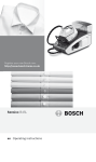
OWNER’S
MANUAL
FASTER &
EASIER
FOR 1996
AND
NEWER
OBD II
VEHICLES
T60
DIGITAL
OBD2/CAN
CAR SCANNER
,
OWNER S MANUAL
Table of Contents
1. INTRODUCTION---------------------------------------------------------------------------4
1.1 WHAT IS OBD?-------------------------------------------------------------------------4
1.2 Safety Precautions and Warnings-----------------------------------------------5
1.3 Vehicle Coverage----------------------------------------------------------------------5
1.4 Data Link Connector (DLC) Location-----------------------------------------7
1.5 How To Use . . . .---------------------------------------------------------------------7
1.6 Easy To Define . . . .-----------------------------------------------------------------7
1.7 OBD2 Readiness Monitors---------------------------------------------------------8
1.8 OBD2 Monitor Readiness Status------------------------------------------------9
1.9 Diagnostic Trouble Code (DTC):-----------------------------------------------11
2. PRODUCT INFORMATION------------------------------------------------------------12
2.1 Tool Descri ption------------------------------------------------------------------------12
2.2 Specifications---------------------------------------------------------------------------13
2.3 Accessories Included--------------------------------------------------------------13
2.4 Navigation Characters--------------------------------------------------------------14
2.5 Keyboard--------------------------------------------------------------------------------14
2.6 Vehicle Power--------------------------------------------------------------------------14
2.7 Code Lookup---------------------------------------------------------------------------14
2.8 Product Setup-------------------------------------------------------------------------15
2.9 Vehicle Coverage--------------------------------------------------------------------19
2.10 Product Troubleshooting-----------------------------------------------------------20
3. OPERATING INSTRUCTIONS-------------------------------------------------------21
3.1 Reading Codes-------------------------------------------------------------------------21
3.2 Erasing Codes-------------------------------------------------------------------------24
3.3 Datastream------------------------------------------------------------------------------26
3.4 Reading Freeze Frame Data-----------------------------------------------------28
3.5 Retrieving I/M Readiness Status-----------------------------------------------29
2
OBD2 CODE READER
,
OWNER S MANUAL
3.6 O2 Monitor Test-------------------------------------------------------------------32
3.7 On-Board Monitor Test---------------------------------------------------------33
3.8 Component Test------------------------------------------------------------------35
3.9 Viewing Vehicle Information---------------------------------------------------37
3.10 Modules Present------------------------------------------------------------------38
4. Appendix--------------------------------------------------------------------------------39
4.1 Appendix 1 PID List---------------------------------------------------------------39
4.2 Appendix 2 In-use Performance Tracking Data List---------------45
5. Warranty and Service--------------------------------------------------------------48
5.1 Limited One Year Warranty---------------------------------------------------48
5.2 Service Procedures--------------------------------------------------------------49
OBD2 CODE READER
3
,
OWNER S MANUAL
1. INTRODUCTION
1.1 WHAT IS OBD?
Definition: Onboard Diagnostics II - A second-generation emissions
diagnostic system required on all 1996 and newer vehicles (thoug h some
1994 and 1995 model year vehicles were equi pped with early versions of
the system).
This OBD2/EOBD/CAN Code Reader is designed to work on all OBD2
compliant vehicles (include all 1996 and newer cars, lig ht trucks and SUVs
sold in the United States). OBD2 was adopted as part of a government
mandate to lower vehicle emissions. This sophisticated program in the
vehicle’s main computer system is designed to detect failures in a range
of systems, and can be accessed throug h vehicle’s 16-pin Data Link
Connector (DLC) which is usually located under the dashboard. For OBD
systems,if a problem is found,the vehicle’s computer turns on the “CHECK
ENGINE” lig ht to warn the driver,and sets a Diagnostic Trouble Code (DTC)
to identify where the problem occurred. A special diagnostic tool, such
as this OBD2 Code Reader, is required to retrieve these codes throug h
vehicle’s Data Link Connector (DLC) ,which consumers and professionals
use as a starting point for repairs.
4
OBD2 CODE READER
,
OWNER S MANUAL
1.2 Safety Precautions and Warnings
To prevent personal injury or damage to vehicles and/or the scan
tool, read this instruction manual first and observe the following safety
precautions at a minimum whenever working on a vehicle:
Always perform automotive testing in a safe environment.
Wear safety eye protection that meets ANSI standards.
Keep clothing,hair,hands,tools,test equi pment,etc. away from
all moving or hot engine parts.
Operate the vehicle in a well ventilated work area: Exhaust gases
are poisonous.
Put blocks in front of the drive wheels and never leave the
vehicle unattended while running tests.
Use extreme caution when working around the ignition coil,
distributor cap, ignition wires and spark plugs. These components create
hazardous voltages when the engine is running.
Put the transmission in PARK (for automatic transmission) or
NEUTRAL (for manual transmission) and make sure the parking
brake is engaged.
Keep a fire extinguisher suitable for gasoline/chemical/ electrical
fires nearby.
Don't connect or disconnect any test equi pment while the
ignition is on or the engine is running.
Keep the scan tool dry,clean,free from oil/water or grease. Use
a mild detergent on a clean cloth to clean the outside of the scan
tool,when necessary.
1.3 Vehicle Coverage
This OBD2 Code Reader is designed to work on all OBD2 compliant
vehicles (include all 1996 and newer cars, lig ht trucks and SUVs sold in
OBD2 CODE READER
5
,
OWNER S MANUAL
the United States), also including those equi pped with the next-generation
protocol
-- Control Area Network (CAN). It is required by EPA that all 1996 and
newer vehicles (cars,lig ht trucks and SUVs) sold in the United States must
be OBD2 compliant and this includes all Domestic, Asian and European
vehicles.
A small number of 1994 and 1995 model year gasoline vehicles are OBD2
compliant. To verify if a 1994 or 1995 vehicle is OBD2 compliant,check the
Vehicle Emissions Control Information (VECI) Label which is located
under the hood or by the radiator of most vehicles. If the vehicle is
OBD2 compliant, the label will designate “OBD II Certified”. Additionally,
Government regulations mandate that all OBD2 compliant vehicles must
have a “common” 16-pin Data Link Connector (DLC).
A. The Vehicle Emissions Control Information (VECI) Label.
This label is located under the hood or by the radiator of most vehicles. If
the vehicle is OBD2 compliant,the label will state “OBD II Certified.”
B. Government Regulations require that all OBD 2 compliant vehicles must
have a “common” sixteen-pin Data Link Connector (DLC). Some 1994
and1995 vehicles have 16-pin connectors butare not OBD 2 compliant.
Only those vehicles with a Vehicle Emissions Control Label stating
OBDIICertified”are OBD2 compliant.
6
OBD2 CODE READER
,
OWNER S MANUAL
1.4 Data Link Connector (DLC) Location
The 16-pin DLC is usually located under the instrument panel (dash),within
12 inches(300 mm) of center of the panel,on the driver’s side of most
vehicles. It should be easilyaccessible and visible froma kneeling position
outside the vehicle with the door open. For some Asian or European
vehicles, the DLC is located behind the ashtray and the ashtray must be
removed toaccess the connector.
1.5 How To Use . . . .
1. Turn the ignition off.
2. Connect the OBD2 Code Reader’s cable and the vehicle’s 16-pin Data
Link Connector (DLC).
3. Turn the ignition on. But do not start the engine.
4. Turn the OBD2 Code Reader’s power on.
5. Press the Y button. A sequence of messages showing the OBD2
protocols will be observed on the display until the vehicle protocol is
detected.
1.6 Easy To Define . . . .
1. The Code Reader retrieves stored codes,Freeze Frame data and I/M
Readiness status.
OBD2 CODE READER
7
,
OWNER S MANUAL
2. Codes, I/M Readiness status and Freeze Frame data are displayed on
the OBD2 Code Reader’s LCD display screen. System status is indicated
by LED indicators.
3. Read code definitions from the OBD2 Code Reader’s LCD display.
4. View Freeze Frame data.
5. DLC
1.7 OBD2 Readiness Monitors
An important part of a vehicle’s OBD2 system is the Readiness Monitors,
which are indicators used to find out if all the emission components have
been evaluated by the OBD2 system. They are runnung perodic tests on
specific systems and components to ensure that they are performing within
allowable limits. Currently, there are eleven OBD2 Readiness Monitors (or
I/M Monitors) defined by the U.S. Environmental Protection Agency (EPA).
Not all monitor are supported by all vehicles and the exact number of
monitors in any vehicle depends on their manufacturer’s emissions control
strategy.
Continuous Monitors - Some of the vehicle components or systems
arecontinuously tested by the vehicle’s OBD2 system, while others are
testedonly under specific vehicle operating conditions. The continuously
monitoredcomponents listed below are always ready:
1.Misfire; 2.Fuel System;
3. Comprehensive components (CCM).
8
OBD2 CODE READER
,
OWNER S MANUAL
Once vehicle is running,the OBD2 system is continuously checking the
above components, monitoring key engine sensors, watching for engine
misfire and monitoring fuel demands.
Non-Continuous Monitors - Unlike the continuous monitors, many
emissionsand engine system components require the vehicle to be
operatedunder specific conditions before the monitor is ready. These
monitors are termed Non-Continuous Monitors and are listed below:
1. EGR System
2. O2 Sensors 3. Catalyst
4. Evaporative System
5. O2 Sensor Heater
6. Secondary Air
7. Heated Catalyst 8. A/C System
1.8 OBD2 Monitor Readiness Status
OBD2 system must indicate whether or not the vehicle’s PCM’s monitor
system has completed testing on each component. Components that have
been tested will be reported as “Reasy”,or “Complete”. The purpose of
recording readiness status is to allow inspectors to determine if the
vehicle’s OBD2 system has tested all the components and /or system.
The powertrain control module (PCM) sets a monitor to Ready or
Complete”after an appropriate drive cycle has been performed. The
drive cycle that enable a monitor and sets readiness codes to “Ready”
varies for each individual monitor. Once a monitor is set as “Ready” or
Complete”,it will remain in this state. A number of factors,including erasing
of diagnostic trouble codes (DTCs) with a code reader or a disconnected
battery, can result in Readiness Monitors being set to “Not Ready”.
OBD2 CODE READER
9
,
OWNER S MANUAL
Since the three continuous monitors are constantly evaluating, they will be
reported as “Ready” all the time. If testing of a particular supported noncontinuous monitor has not been completed, the monitor status will be
reported as “Not Ready”.
In order for the OBD monitor system to become ready, the vehicle should
be driven under a variety of normal operating conditions. These operating
conditions may include a mix of hig hway driving and stop and go, city
type driving, and at least one overnig ht-off period. For speific information
on getting your vehicle’s OBD monitor system ready, please consult your
vehicle owner’s manual.
1.9 Diagnostic Trouble Code (DTC):
OBD2 Diagnostic Trouble Codes(DTC) are codes that are stored by the
onboard computer diagnostic system in response to a problem found in
the vehicle. They are meant to guide you to the proper service procedure
in the vehicle’s service manual. OBD2 Diagnostic Trouble Codes(DTC)
consist of a five digit alphanumeric code. The first character, a letter,
identifies which control system sets the code. The other four characters,all
numbers, provide additional information on where the DTC originated and
the operating conditions that caused it to set. Here below is an example
to illustrate the structure of the digits.
10
OBD2 CODE READER
,
OWNER S MANUAL
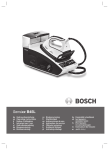
Diagnostic Trouble Code (DTC) Example"
B-Body
C-Chassis
P-Powertrain
U-Network
P 0 2 0 1
Code type Generic(SAE):
PO,P2,P34-P39
Bo,B3
Co,C3
Uo,U3
Manufacturer Specific:
P1,P30-P33
B1,B2
C1,C2
U1,U2
Sub-system
1- Fuel and Air Metering
2-Fuel and Air Metering
3-Lgnition System or Engine Misfire
4-Auxiliary Emission Controls
5-Vehicle Speed Control and ldle Controls
6-Computer Output Circuits
7-Transmission Conerols
8-Transmission Conerols
Ldentifies What section of the system is
malfunctioning
OBD2 CODE READER
11
,
OWNER S MANUAL
2. PRODUCT INFORMATION
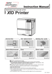
2.1 Tool Description
7
1
2
3
4
5
6
1 LCD DISPLAY --Indicates test results. Backlit,128x64 pixel display with
contrast adjustment.
2 Y BUTTON --Confirms a selection (or action) from a menu. When
a DTC's definition covers more than one screen, it is used to move
down to the next screen for additional data. It is also used to reset
the tool when being pressed and held simultaneously with the N button
for at least 3 seconds.
3 N BUTTON-- Cancels a selection (or action) from a menu or returns to
the menu. It is also used to setup the system or exit the DTC Lookup
12
OBD2 CODE READER
,
OWNER S MANUAL
screen when being pressed and held for at least 3 seconds.
UP SCROLL BUTTON -- Moves up throug h menu and submenu
items in menu mode. When more than one screen of data is retrieved,
moves up throug h the current screen to the previous screens for
additional data.
DOWN SCROLL BUTTON -- Moves down throug h menu and
5
submenu items in menu mode. When more than one screen of data is
retrieved,moves down throug h the current screen to the next screens
for additional data.
6
POWER BUTTON -- press and hold POWER button for at least 3
seconds power ON or OFF.
7 OBD II CONNECTOR -- Connects the scan tool to the vehicle's Data
Link Connector (DLC).
4
2.2
Specifications
Display: Backlit,128 x 64 pixel display with contrast adjustment
Operating Temperature: 0 to 50°C (32 to 122 F°)
Storage Temperature: -20 to 70°C (-4 to 158 F°)
Power: 8 to 16 Volts provided via vehicle battery
Dimensions:
Length
Width
Heig ht
209 mm (8.22")
107 mm (3.74")
37 mm (1.38")
6)
NW: 0.73kg (1.611b),GW: 0.98kg(2.161b)
2.3
Accessories Included
1) User's Manual — Instructions on tool operations
2) CD — Includes user's manual,DTC lookup library and etc.
3) OBD2 cable - Provides power to tool and communicates
between tool and vehicle
4) USB Cable - Used to upgrade the scan tool
5) Carry Case - A nylon case to store the scan tool when not in use
OBD2 CODE READER
13
,
OWNER S MANUAL
2.4
Navigation Characters
Characters used to help navigate the scan tool are:
1)" " -- Indicates current selection.
2)" " -- A DOWN Arrow indicates additional information is
available on the next screen.
3)" "-- An UP Arrow indicates additional information is available
on the previous screen.
4) "Pd" -- Identifies a Pending DTC when viewing DTCs.
5) "$" -- Identifies the control module number from which the data
is retrieved.
2.5
Keyboard
No solvents such as alcohol are allowed to clean the keypad or display.
Use a mild nonabrasive detergent and a soft cotton cloth. Do not soak the
keypad as the keypad is not waterproof.
2.6
Vehicle Power
The power of the scan tool is provided via the vehicle Data Link Connector
(DLC). Just follow the steps below to turn on the scan tool:
1) Connect the OBD II Cable to scan tool.
2) Find DLC on vehicle.
A plastic DLC cover may be found for some vehicles and you need to
remove it before plugging the 0BD2 cable.
3)Plug OBD II Cable to the vehicle's DLC.
2.7
Code Lookup
The Code Lookup function is used to search for definitions of DTCs stored
in the Scan Tool.
1) From the Main Menu, use the UP/DOWN scroll buttons to select DTC
Lookup and press the Y button.
14
OBD2 CODE READER
,
OWNER S MANUAL
Main Menu
===========================
1) Diagnostics
2) DTC Lookup
3) System Setup
4) Tool Information
2) From the DTC Lookup menu, use the N button to move to the desired
character,use ^ or ^ arrow buttons to change selected digit/character and
press Y button to confirm.
DTC Lookup
==========================
P0001
[N] = Next Character
[ ] [ ] = Change Digit
[Y] = Confirm
Hold [N] = Exit
3)View the DTC definition on screen
4)To view next or previous DTC in the built-in DTC library,use
[
] or [
] arrow button.
5)To enter another DTC,press [N] button to return to previous screen
6)To exit to Main Menu,press and hold N button for at least 3 seconds.
•
For manufacturer specific codes,you need to select a vehicle
make on an additional screen to look for DTC definitions.
•
If definition could not be found (SAE or Manufacturer Specific),
the Scan Tool displays "DTC definition not found! Please refer
to vehicle service manual!"
2.8 Product Setup
The scan tool allows you to make the following adjustments and settings:
1) Contrast adjustment: Adjusts the contrast of the LCD display.
2) Unit of measure: Sets the Unit of Measure to English or Metric.
3) Tool self-test: Tests the LCD display and the keyboard.
OBD2 CODE READER
15
,
OWNER S MANUAL
• The settings of the unit will remain until change to the existing settings is
made.
To enter the setup menu mode
From the keyboard: Press and hold the N button for at least 3 seconds
until System Setup menu shows up. Follow the instructions to make
adjustments and settings as described in the following setup options.
System Setup
=======================
1) Contrast
2) Unit of Measure
3) Tool Self-test
4) Update DTC
From the Main Menu: Use the UP/DOWN scroll buttons to select System
Setup,and press the Y button. Follow the instructions to make adjustments
and settings as described in the following setup options.
Main Menu
========================
1) Diagnostics
2) DTC Lookup
3) System Setup
4) Tool Information
Contrast Adjustment
1) From the System Setup menu,use the UP/DOWN scroll buttons to select
Contrast,and press the Y button.
System Setup
=======================
1) Contrast
2) Unit of Measure
3) Tool Self-test
4) Update DTC
16
OBD2 CODE READER
,
OWNER S MANUAL
2) From the Contrast menu, use the UP/DOWN scroll buttons to decrease
or increase the contrast
Contrast
==========================
Contrast (47%)
3) Press the Y button to save your selection and return to previous menu.
4) Press the N button to return to Main Menu.
Unit of Measurement
English is the default measurement unit.
1) From the System Setup menu,use the UP/DOWN scroll buttons to select
Unit of Measure and press the Y button.
System Setup
==========================
1) Contrast
2) Unit of Measure
3) Tool Self-test
4) Update DTC
2) From the Unit of Measure menu, use the UP/DOWN scroll buttons to
select the desired unit of measurement.
Unit of Measure
==========================
1) English
2) Metric
3) Press the Y button to save your selection and return to previous menu.
OBD2 CODE READER
17
,
OWNER S MANUAL
4) Press the N button to return to System Setup menu
A. Display test
The Display Test is used to check the LCD display.
1) From the System Setup menu, use the UP/DOWN scroll buttons to
select Tool Self-Test,and press the Y button.
System Setup
===========================
1) Contrast
2) Unit of Measure
3) Tool Self-test
4) Update DTC
YY
2) Select Display Test from the Tool Self-Test menu and press the Y
button.
Tool Self-test:
==========================
1) Display Test
2) Keyboard Test
3) Press the Y button again to start test. Look for missing spots in the
solid black characters.
Display Test
========================
Press [Y ] to test
Look for missing
spots in characters.
Press [N] to return
4) When completed,press the N button to return.
B. Keyboard Test
The Keyboard Test is used to verify that the keys are functioning properly.
18
OBD2 CODE READER
,
OWNER S MANUAL
1) Use the UP/DOWN scroll buttons to select Keyboard Test from the Tool
Self-Test menu,and then press the Y button.
Tool Self-test:
=========================
1) Display Test
2) Keyboard Test
2) Press any key to start test. When you press a key,the key name should
be observed on the display. If the name does not show up,then the key is
not functioning properly.
Keyboard Test
==========================
Press any key to
Start test to
display name.
Key:
Double [N] to return
3) Double press [N] to return to the menu
2.9
Vehicle Coverage
The Maxscan™ OBDII/EOBD Scanner is specially designed to work with
all OBD II compliant vehicles, including those equi pped with the nextgeneration protocol ~ Control Area Network (CAN). It is required by EPA
that all 1996 and newer vehicles (cars and lig ht trucks) sold in the United
States must be OBD II compliant and this includes all Domestic, Asian and
European vehicles. A small number of 1994 and 1995 model year gasoline
vehicles are OBD II compliant. To verify if a 1994 or 1995 vehicle is OBD
II compliant, check the Vehicle Emissions Control Information (VECI) Label
which is located under the hood or by the radiator of most vehicles. If
the vehicle is OBD II compliant, the label will designate "OBD II Certified".
Additionally, Government regulations mandate that all OBD II compliant
OBD2 CODE READER
19
,
OWNER S MANUAL
vehicles must have a "common" sixteen-pin Data Link Connector (DLC).
For your vehicle to be OBD II compliant it must have a 16-pin DLC
(Data Link Connector) under the dash and the Vehicle Emission Control
Information Label must state that the vehicle is OBD II compliant.
2.10 Product Troubleshooting
Vehicle Linking Error
A communication error occurs if the scan tool fails to communicate with
the vehicle's ECU (Engine Control Unit). You need to do the following to
check up:
√ Verify that the ignition is ON;
√ Check if the scan tool's OBD II connector is securely connected to the
vehicle's DLC;
√ Verify that the vehicle is OBD2 compliant;
√ Turn the ignition off and wait for about 10 seconds. Turn the ignition
back to on and continue the testing.
√ Verify the control module is not defective
Operating Error
If the scan tool freezes, then an exception occurs or the vehicle's ECU
(Engine Control Unit) is too slow to respond to requests. You need to do
the following to reset the tool:
√ Press and hold the Y and N buttons simultaneously for at least 3
seconds to reset the scan tool.
√ Turn the ignition off and wait for about 10 seconds. Turn the ignition
back to on and continue the testing.
Scan Tool doesn't power up
If the scan tool won't power up or operates incorrectly in any other way,
you need to do the following to check up:
√ Check if the scan tool's OBD II connector is securely connected to the
vehicle's DLC;
20
OBD2 CODE READER
,
OWNER S MANUAL
√ Check if the DLC pins are bent or broken. Clean the DLC pins if
necessary.
√ Check vehicle battery to make sure it is still good with at least 8.0
volts.
3. OPERATING INSTRUCTIONS
When more than one vehicle control module is detected by the scan
tool, you will be prompted to select the module where the data may be
retrieved. The most often to be selected are the Powertrain Control Module
[PCM] and Transmission Control Module [TCM]
3.1 Reading Codes
CAUTION: Don't connect or disconnect any test equi pment with ignition on
or engine running.
Reading Codes can be done with the key on engine off (KOEO) or
with the key on engine running (KOER).
Stored Codes are also known as "hard codes" or "permanent codes".
These codes cause the control module to illuminate the malfunction
indicator lamp (MIL) when emission-related fault occurs.
Pending Codes are also referred to as "maturing codes" or
"continuous monitor codes". They indicate problems that the control
module has detected during the current or last driving cycle but are not
considered serious yet. Pending Codes will not turn on the malfunction
indicator lamp (MIL). If the fault does not occur within a certain number of
warm-up cycles,the code clears from memory.
1) Turn the ignition off.
2) Locate the vehicle's 16-pin Data Link Connector (DLC).
3) Plug into the scan tool cable connector to the vehicle's DLC.
4) Turn the ignition on. Engine can be off or running.
OBD2 CODE READER
21
,
OWNER S MANUAL
5) Press the Y button to enter the Main Menu. Use the UP/DOWN
scroll buttons to select Diagnostics from the menu.
Main Menu
=========================
1) Diagnostics
2) DTC Lookup
3) System Setup
4) Tool Information
6) Press the Y button to confirm. A sequence of messages displaying the
OBD2 protocols will be observed on the display until the vehicle protocol
is detected
•
If the scan tool fails to communicate with the vehicle's
ECU(Engine Control Unit), a"LINKING ERROR!" messageshows up on the
display.
Verify that the ignition is ON;
Check if the scan tool's OBD II connector is securely
connected to the vehicle's DLC;
Verify that the vehicle is OBD2 compliant;
Turn the ignition off and wait for about 10 seconds. Turn the
ignition back to on and repeat the procedure from step 5.
•
If the "LINKING ERROR " message does not go away, then there
mig ht be problems for the scan tool to communicate with the vehicle.
Contact your local distributor or the manufacturer's customer service
department for assistance.
7) After the result of State Emission Test is displayed (MIL status,DTC
counts,Monitor status),press any key for the Diagnostic Menu to come up.
22
OBD2 CODE READER
,
OWNER S MANUAL
State Emis. Test
=========================
MIL Status
OFF
Codes Found
1
Monitors N/A
4
Monitors OK
3
Monitors INC
3
8 Use the UP/DOWN scroll buttons to select Read Codes from the menu
and press the Y button.
Diagnostic Menu
=======================
1) Read Codes
2) Erase Codes
3) Datastream
4) Freeze Frame
5) I/M Readiness
6) O2 Monitor Test
9) Use the UP/DOWN scroll buttons to select Stored Codes or Pending
Codes from the Trouble Codes menu and press the Y button.
Trouble Codes
=========================
1) Stored Codes
2) Pending Codes
If there are no Diagnostic Trouble Codes present, the display will indicate
"No Codes Are Stored in the Module!"
10) View DTCs and their definitions on screen.
$11
P0115
pd 1/1
Generic
==========================
Engine Coolant Temperature
Sensor 1 Circuit
OBD2 CODE READER
23
,
OWNER S MANUAL
•
The control module number,sequence of the DTCs,total number
of codes detected and type of codes (Generic or Manufacturer specific,
Stored or Pending codes) will be observed on the upper rig ht hand corner
of the display.
•
When a DTCs definition covers more than one screen,use the Y
button,as necessary,to view any additional information.
11) If more than one DTC is found, use the UP/DOWN scroll buttons, as
necessary,until all the codes have been shown up.
If the retrieved DTCs contain any manufacturer specific or enhanced
codes, you will be prompted to select the vehicle manufacturer to
view DTC definitions. Use the UP/DOWN scroll buttons to select the
manufacturer and then press the Y button to confirm.
Stored Codes
===========================
Manufacturer Specific
CodesFound! Press any
key to next screen
to select manufacturer.
Vehicle Manufaturer
========================
1) Alfa Romeo
2) Audi/VW
3) BMW
4) Buick
5) Cadillac
6) Chevrolet
If the manufacturer for your vehicle is not listed, use the UP/DOWN
scroll buttons to select Other and press the Y button.
3.2 Erasing Codes
CAUTION: Erasing the Diagnostic Trouble Codes may allow the scan
tool to delete not only the codes from the vehicle's on-board computer,
but also "Freeze Frame" data and manufacturer specific enhanced data.
24
OBD2 CODE READER
,
OWNER S MANUAL
Further, the I/M Readiness Monitor Status for all vehicle monitors is reset
to Not Ready or Not Complete status. Do not erase the codes before the
system has been checked completely by a technician.
This function is performed with key on engine off(KOEO). Do not start
the engine.
1) If you decide to erase the DTCs, use the UP/DOWN scroll buttons to
select Erase Codes from the Diagnostics Menu and press the Y button
Diagnostic Menu
=======================
1) Read Codes
2) Erase Codes
3) Datastream
4) Freeze Frame
5) I/M Readiness
6) O2 Monitor Test
2)
A warning message comes up asking for your confirmation.
Erase Codes
========================
Erase trouble codes!
Are you sure?
YES <NO >
If you do not want to proceed with erasing the codes,press the
Y/N button to exit. A message of "Command Cancelled" will show
up. Press any key to return to Diagnostic Menu.
If you do wish to proceed to erase the codes, then use the UP/
DOWN scroll buttons to select YES. Press the Y button to confirm.
3) If the codes are cleared successfully, an "Erase Done!" confirmation
message will show on the display. Press any button to return to the
Diagnostic Menu.
OBD2 CODE READER
25
,
OWNER S MANUAL
Erase Codes
==========================
Erase Done!
Press any key to con
4) If the codes are not cleared, then a message "Erase Failure! Turn Key
on with Engine off!" will appear.
Erase Codes
============================
Erase Failure!
Turn Key on with
Engine Off !
4) Press any button to return to the Diagnostic Menu.
3.3 Datastream
The Datastream function allows viewing of live or real time PID data of the
vehicle's computer modules.
1) To view datastream, use the UP/DOWN scroll buttons to select
Datastream from the Diagnostic Menu and press the Y button.
Diagnostic Menu
=======================
1) Read Codes
2) Erase Codes
3) Datastream
4) Freeze Frame
5) I/M Readiness
6) O2 Monitor Test
2) Wait a few seconds while the Scan Tool validates the PID MAP.
Live Data
========================
Reading PID.01
-Please Wait-
26
OBD2 CODE READER
,
OWNER S MANUAL
3) To view entire data set, use the UP/DOWN scroll buttons to select
Complete Data Set from the View Data Menu and press the Y button.
View Data
========================
1)Complete Data Set
2)Custom Data Set
3)Unit of Measure
4) View live PIDs on the screen. Use the UP/DOWN scroll buttons for more
PIDs if an UP/DOWN arrow at the upper rig ht hand corner of the screen
indicates that more than one page of data is available.
A down arrow indicates that there are more data available on the
next screen.
An up arrow indicates that there are more data available on the
previous screen.
Live Data
=========================
DTC_CNT
1
FUELSYS1
OL_Drive
FUELSYS2
N/A
LOADPCT(%)
0.0
ETC(
)
-4.0
SHRTFT1(%)
0.0
5) To return to View Data menu,press the N button.
6) To view custom data set,use the UP/DOWN scroll buttons to
select Custom Data Set from the View Data menu and press the
Y button.
View Data
===========================
1)Complete Data Set
2)Custom Data Set
3)Unit of Measure
OBD2 CODE READER
27
,
OWNER S MANUAL
7) Use the UP/DOWN scroll buttons to move up and down list, and press
the Y button to select or deselect data parameters to view. Selected
parameters are marked with solid squares.
Custom Data Set
========================
DTC_CNT
FUELSYS1
FUELSYS2
LOADPCT(%)
ETC(F )
SHRTFT1(%)
8) Press the N button to view selected PIDs on screen.
Live Data
==========================
DTC_CNT
1
FUELSYS2
N/A
ETC( F )
-4.0
LONGFT1(%)
0.0
9 Use the N button to return to View Data menu and / or the Diagnostic
Menu.
3.4 Reading Freeze Frame Data
1)
To view Freeze Frame Data, use the UP/DOWN scroll buttons to
select Freeze Frame from the Diagnostic Menu and press the Y button
Diagnostic Menu
========================
1) Read Codes
2) Erase Codes
3) Datastream
4) Freeze Frame
5) I/M Readiness
6) O2 Monitor Test
28
OBD2 CODE READER
,
OWNER S MANUAL
2) Wait a few seconds while the Scan Tool validates the PID MAP.
Freeze Frame
============================
Reading PID.01
-Please Wait-
3) If the retrieved information covers more than one screen, then a down
arrow will appear. Use the DOWN scroll button, as necessary, until all the
data have been shown up.
Freeze Frame
========================
DTCFRZF
1630
FUELSYS1
OL_Drive
FUELSYS2
N/A
LOADPCT(%)
0.0
ETC( F )
-4.0
SHRTFT1(%)
0.0
If there is no freeze frame data available, an advisory message shows on
the display.
4) Press the N button to return to the Diagnostic Menu.
3.5 Retrieving I/M Readiness Status
I/M Readiness function is used to check the operations of the Emission
System on OBD2 compliant vehicles. It is an excellent function to use
prior to having a vehicle inspected for compliance to a state emissions
program.
Some latest vehicle models may support two types of I/M Readiness
tests:
A. Since DTCs Cleared - indicates status of the monitors since the DTCs
are erased.
B.
This Drive Cycle - indicates status of monitors since the
OBD2 CODE READER
29
,
OWNER S MANUAL
beginning of the current drive cycle.
An I/M Readiness Status result of "NO" does not necessarilyindicate
that the vehicle being tested will fail the state I/Minspection. For some
states,one or more such monitors maybe allowed to be "Not Ready" to
pass the emissions inspection.
"OK" - Indicates that a particular monitor being checked has completed
its diagnostic testing.
"INC" - Indicates that a particular monitor being checked has not
completed its diagnostic testing.
"N/A" - The monitor is not supported on that vehicle.
1) Use the UP/DOWN scroll buttons to select I/M Readiness from the
Diagnostic Menu and press the Y button.
Diagnostic Menu
======================
1) Read Codes
2) Erase Codes
3) Datastream
4) Freeze Frame
5) I/M Readiness
6) O2 Monitor Test
2) Wait a few seconds while the Scan Tool validates the PID MAP.
I/M Readiness
==========================
Reading PID.01
-Please Wait-
3) If the vehicle supports both types of tests,then both types will be shown
on the screen for selection.
30
OBD2 CODE READER
,
OWNER S MANUAL
I/M Readiness
==========================
Since DTCs Cleared
This Drive Cycle
4) Use the UP/DOWN scroll buttons, as necessary, to view the status of
the MIL lig ht ("ON" or "OFF”) and the following monitors:
Misfire monitor — Misfire monitor
Fuel System Mon — Fuel System Monitor
Comp. Component - Comprehensive Components Monitor
EGR - EGR System Monitor
Oxygen Sens Mon — 02 Sensors Monitor
Catalyst Mon — Catalyst Monitor
EVAP System Mon — Evaporative System Monitor
Oxygen Sens htr --02 Sensor Heater Monitor
Sec Air System - Secondary Air Monitor
Htd Catalyst -- Heated Catalyst Monitor
A/C Refrig Mon - A/C system Monitor
Since DTCs Cleared
=========================
MIL Status
OFF
Misfire Monitor
OK
Fuel System Mon
OK
Comp.Component
OK
Catalyst Mon
INC
Htd Catalyst
N/A
5) If the vehicle supports readiness test of "This Drive Cycle", a screen of
the following will be displayed:
OBD2 CODE READER
31
,
OWNER S MANUAL
This Drive Cycle
========================
MIL Status
OFF
Misfire Monitor
OK
Fuel System Mon
OK
Comp.Component
OK
Catalyst Mon
INC
Htd Catalyst
N/A
6) Press the N button to return to the Diagnostic Menu.
3.6 O2 Monitor Test
OBD2 regulations set by SAE require that relevant vehicles monitor and
test the oxygen (O2) sensors to identify problems related to fuel efficiency
and vehicle emissions. These tests are not on-demand tests and they are
done automatically when engine operating conditions are within specified
limits. These test results are saved in the on-board computer's memory.
The O2 Monitor Test function allows retrieval and viewing of O2 sensor
monitor test results for the most recently performed tests from the vehicle's
on-board computer.
The O2 Monitor Test function is not supported by vehicles which
communicate using a controller area network (CAN). For O2 Monitor Test
results of CAN-equi pped vehicles,see chapter "On-Board Mon. Test".
1) Use the UP/DOWN scroll buttons to select O2 Monitor Test from the
Diagnostic Menu and press the Y button.
Diagnostic Menu
=======================
1) Read Codes
2) Erase Codes
3) Datastream
4) Freeze Frame
5) I/M Readiness
6) O2 Monitor Test
2) Wait a few seconds while the Scan Tool validates the PID MAP.
32
OBD2 CODE READER
,
OWNER S MANUAL
O2 Monitor Test
=====================
Reading PID.01
-Please Wait3 Use the UP/DOWN scroll buttons to select the O2 sensor from the O2
Monitor Test menu and press the Y button.
O2 Monitor Test
==========================
O2 Bank1 Sensor1
O2 Bank1 Sensor2
4)View test results of selected O2 sensor
O2 Bank1 Sensor2
=========================
Rich-Lean Threshd(V)
MOD:
$11
MEAS:
0.580
MIN:
-----MAX:
-------
5) Use the UP/DOWN scroll buttons to view more screens of data if an
UP/DOWN arrow displays.
6) Press the N button to return to the previous menus.
3.7 On-Board Monitor Test
The On-Board Monitor Test is useful after servicing or after erasing a
vehicle's control module memory. The On-Board Monitor Test for non-CANequi pped vehicles retrieves and displays test results for emission-related
powertrain components and systems that are not continuously monitored.
The On-Board Monitor Test for CAN-equi pped vehicles retrieves and
OBD2 CODE READER
33
,
OWNER S MANUAL
displays test results for emission-related powertrain components
and systems that are and are not continuously monitored. Test and
components IDs are determined by the vehicle manufacturer.
1) Use the UP/DOWN scroll buttons to select On-Board Mon.Test from the
Diagnostic Menu and press the Y button.
Diagnostic Menu
=======================
07) On-Board Mon.Test
08) Component Test
09) Vehicle Info.
10) Modules Present
11) Unit of Measure
2) Wait a few seconds while the Scan Tool validates the PID MAP.
On-Board Mon.Test
===========================
Reading PID.01
-Please Wait-
3) From the On-Board Mon.Test menu,use the UP/DOWN scroll buttons to
select the test to view and press the Y button.
On-Board Mon.Test
==========================
Test $01 Data
Test $05 Data
Test $09 Data
For CAN-equi pped vehicles,the test selections can be as below:
34
OBD2 CODE READER
,
OWNER S MANUAL
On-Board Mon.Test
==========================
O2 Mon.B1S1
O2 Mon.B1S2
Catalyst Mon.B1
EGR Mon.Bank1
1) Use the UP/DOWN scroll buttons to select desired monitor from OnBoard Mon.Test menu and press the Y button.
2) View the test data on screen.
Test $01 Data
========================
ID :
00
MOD:
$11
MEAS:
0
MAX :
0
MIN :
---------STS:
OK
For CAN-equi pped vehicles,the test results displayed can be as below:
O2 Mon. B1S1
=========================
Rich-Lean Threshd(V)
MEAS :
MIN :
MAX:
STAT:
0.450
0.312
0.630
OK
3) Press the N button to return to the previous menu
3.8 Component Test
The Component Test function allows initiating a leak test for the vehicle's
EVAP system. The Scan Tool itself does not perform the leak test, but
commands the vehicle's on-board computer to start the test. Different
vehicle manufacturers mig ht have different criteria and methods for
stopping the test once it has been started. Before starting the Component
Test,refer to the vehicle service manual for instructions to stop the test.
OBD2 CODE READER
35
,
OWNER S MANUAL
1) Use the UP/DOWN scroll buttons to select Component Test from the
Diagnostic Menu and press the Y button.
Diagnostic Menu
=====================
07) On-Board Mon.Test
08) Component Test
09) Vehicle Info.
10) Modules Present
11) Unit of Measure
2) Wait a few seconds while the Scan Tool validates the PID MAP.
Component Test
==========================
Reading PID.01
-Please Wait-
3) From the Component Test Menu, use the UP/DOWN scroll buttons to
select the test to be initiated.
Component Test
==========================
Evap Leak Test
4) If the test has been initiated by the vehicle, a confirmation message will
be displayed on the screen.
Component Test
==========================
Command Sent!
Press any key to con.
36
OBD2 CODE READER
,
OWNER S MANUAL
Some vehicles do not allow scan tools to control vehicle systems or
components. If the vehicle under test does not support the EVAP Leak
Test,an advisory message is displayed on the screen.
Component Test
==========================
The selected mode is
Not supported
Press any key to con.
3.9 Viewing Vehicle Information
The Vehicle Information function enables the retrieval of the Vehicle
Identification No.(VIN), Calibration ID(s), Calibration Verification Nos.(CVNs)
and In-use Performance Tracking on 2000 and newer vehicles that
support Mode 9.
1) Use the UP/DOWN scroll buttons to select Vehicle Info, from the
Diagnostic Menu and press the Y button.
Diagnostic Menu
=======================
07) On-Board Mon.Test
08) Component Test
09) Vehicle Info.
10) Modules Present
11) Unit of Measure
If the vehicle does not support this mode ,a message will show on the
display warning that the mode is not supported.
2) Wait a few seconds while the Scan Tool validates the PID MAP.
Vehicle Info.
=========================
Reading PID.01
-Please Wait-
OBD2 CODE READER
37
,
OWNER S MANUAL
3) From the Vehicle Info, menu, use the UP/DOWN scroll buttons to select
the available items to view and press the Y button.
Vehicle Info.
=========================
Calibration ID
Cal. Verif,Number
4) View the vehicle information retrieved.
Calibration ID
==========================
Cal ID1:
30668343
Cal ID2:
08644359
3.10 Modules Present
The Modules Present function allows the viewing of the module IDs and
communication protocols for OBD2 modules in the vehicle.
1) Use the UP/DOWN scroll buttons to select Modules Present from the
Diagnostic Menu and press the Y button.
Diagnostic Menu
=====================
07) On-Board Mon.Test
08) Component Test
09) Vehicle Info.
10) Modules Present
11) Unit of Measure
2) View the modules present with their IDs and communication protocols.
38
OBD2 CODE READER
,
OWNER S MANUAL
Modules Present
=========================
ID
Protocol
_____________________________
$11
ISO 9141-2
4. Appendix
4.1 Appendix 1—PID List
PID Abbreviation
Full Name
DTC_CNT
DTCFRZF
FUELSYS1
FUELSYS2
LOAD_PCT(%)
ETC(°F)
ETC(°C)
SHRTFT1(%)
SHRTFT3(%)
LONGFT1(%)
LONGFT3(%)
SHRTFT2(%)
SHRTFT4(%)
LONGFT2(%)
LONGFT4(%)
FRP(kPa)
DTC Stored Number
DTC
Fuel System 1 Status
Fuel System 2 Status
Calculated Load Value
Engine Coolant Temperature
Engine Coolant Temperature
Short Term Fuel Trim-Bank 1
Short Term Fuel Trim-Bank3
Long Term Fuel Trim-Bank 1
Long Term Fuel Trim-Bank3
Short Term Fuel Trim-Bank2
Short Term Fuel Trim-Bank4
Long Term Fuel Trim-Bank2
Long Term Fuel Trim-Bank4
Fuel Rail Pressure(gauge)
FRP(psi)
Fuel Rail Pressure(gauge)
OBD2 CODE READER
39
,
OWNER S MANUAL
PID Abbreviation
MAP(kPa)
02SL0C
O2B1S1(V)
SHRTFTB1S1(%)
O2B1S2(V)
SHRTFTB1S2(%)
O2B1S3(V)
SHRTFTB1S3(%)
O2B1S4(V)
SHRTFTB1S4(%)
O2B2S1(V)
SHRTFTB2S1(%)
O2B2S2(V)
SHRTFTB2S2(%)
O2B2S3(V)
SHRTFTB2S3(%)
O2B2S4(V)
SHRTFTB2S4(%)
O2BIS1(V)
SHRTFTB1S1(%)
O2B1S2(V)
SHRTFTB1S2(%)
O2B2S1(V)
SHRTFTB2S1(%)
O2B2S2(V)
SHRTFTB2S2(%)
O2B3S1(V)
40
Full Name
Intake Manifold Absolute Pressure
Location of 02 Sensors
O2 Sensor Output Voltage(BlSl)
Short Term Fuel Trim(B 1S1)
O2 Sensor Output Voltage(B 1S2)
Short Term Fuel Trim(Bl S2)
O2 Sensor Output Voltage(BlS3)
Short Term Fuel Trim(BlS3)
O2 Sensor Output Voltage(BlS4)
Short Term Fuel Trim(BlS4)
O2 Sensor Output Voltage(B2Sl)
Short Term Fuel Trim(B2S 1)
O2 Sensor Output Voltage(B2S2)
Short Term Fuel Trim(B2S2)
O2 Sensor Output Voltage(B2S3)
Short Term Fuel Trim(B2S3)
O2 Sensor Output Voltage(B2S4)
Short Term Fuel Trim(B2S4)
O2 Sensor Output Voltage(B2Sl)
Short Term Fuel Trim(B2S 1)
O2 Sensor Output Voltage(BlS2)
Short Term Fuel Trim(BlS2)
O2 Sensor Output Voltage(B2Sl)
Short Term Fuel Trim(B2Sl)
O2 Sensor Output Voltage(B2S2)
Short Term Fuel Trim(B2S2)
02 Sensor Output Voltage(B3Sl)
OBD2 CODE READER
,
OWNER S MANUAL
PID Abbreviation
SHRTFTB3S1(%)
O2B3S2(V)
SHRTFTB3S2(%)
O2B4S1(V)
SHRTFTB4S1(%)
O2B4S2(V)
SHRTFTB4S2(%)
MAP(inHg)
RPM(/min)
VSS(km/h)
VSS(mph)
SPARKADV(\x82)
IAT(°F)
IAT(°C)
MAF(g/s)
MAF(lb/min)
TP(%)
AIR STAT
OBDSUP
02SL0C
RUNTM(sec)
MIL_DIST(km)
MIL DIST(mile)
FRP(kPa)
FRP(PSI)
FRP(kPa)
FRP(PSI)
Full Name
Short Term Fuel Trim(B3Sl)
02 Sensor Output Voltage(B3S2)
Short Term Fuel Trim(B3S2)
02 Sensor Output Voltage(B4Sl)
Short Term Fuel Trim(B4Sl)
O2 Sensor Output Voltage(B4S2)
Short Term Fuel Trim(B4S2)
Intake Manifold Absolute Pressure
Engine RPM
Vehicle Speed Sensor
Vehicle Speed Sensor
Ignition Timing Advance for #1
Intake Air Temperature
Intake Air Temperature
Mass Air Flow Sensor
Mass Air Flow Sensor
Absolute Throttle Position
Commanded Secondary Air Status
OBD Require To Which Vehicle Designed
Location of O2 Sensors
Time Since Engine Start
Distance Travelled While MIL Activated
Distance Travelled While MIL Activated
FuelRail Pres. Relative To Manifold Vacuum
FuelRail Pres. Relative To Manifold Vacuum
Fuel Rail Pressure
Fuel Rail Pressure
OBD2 CODE READER
41
,
OWNER S MANUAL
PID Abbreviation
EQ RATB1S1
O2B1S1(V)
EQ RATB1S2
O2B1S2(V)
EQRATB1S3
O2B1S3(V)
EQ RATB1S4
O2B1S4(V)
EQ RATB2S1
O2B2S1(V)
EQRATB2S2
O2B2S2(V)
EQ RATB2S3
O2B2S3(V)
EQRATB2S4
O2B2S4(V)
EQ RATB1S1
O2B1S1(V)
EQ RATB3S1
EQ RATB1S2
O2B1S2(V)
EQ RATB2S1
O2B2S1(V)
EQ RATB2S2
O2B2S2(V)
O2B3S1(V)
EQ RATB3S2
O2B3S2(V)
42
Full Name
Equivalence Ratio(wide range O2S)(B1S1)
02 Sensor Voltage(wide range O2S)(B1S1)
Equivalence Ratio(wide range O2S)(B1S2)
02 Sensor Voltage(wide range O2S)(B1S2)
Equivalence Ratio(wide range O2S)(B1S3)
02 Sensor Voltage(wide range O2S)(B1S3)
Equivalence Ratio(wide range O2S)(B1S4)
02 Sensor Voltage(wide range O2S)(B1S4)
Equivalence Ratio(wide range O2S)(B2S 1)
02 Sensor Voltage(wide range O2S)(B2S1)
Equivalence Ratio(wide range O2S)(B2S2)
O2 Sensor Voltage(wide range O2S)(B2S2)
Equivalence Ratio(wide range O2S)(B2S3)
O2 Sensor Voltage(wide range O2S)(B2S3)
Equivalence Ratio(wide range O2S)(B2S4)
O2 Sensor Voltage(wide range O2S)(B2S4)
Equivalence Ratio(wide range O2S)(B2S1)
O2 Sensor Voltage(wide range O2S)(B2S1)
Equivalence Ratio(wide range O2S)(B3S1)
Equivalence Ratio(wide rangeO2S)(B1S2)
O2 Sensor Voltage(wide range O2S)(B1S2)
Equivalence Ratio(wide range O2S)(B2S1)
O2 Sensor Voltage(wide range O2S)(B2S1)
Equivalence Ratio(wide range O2S)(B2S2)
O2 Sensor Voltage(wide range O2S)(B2S2)
02 Sensor Voltage(wide range O2S)(B3S1)
Equivalence Ratio(wide range O2S)(B3S2)
02 Sensor Voltage(wide range O2S)(B3S2)
OBD2 CODE READER
,
OWNER S MANUAL
PID Abbreviation
EQ RATB4S1
O2B4S1(V)
EQ RATB4S2
O2B4S2(V)
EGR PTC(%)
EOR_ERR(%)
EVAP_PCT(%)
FLI(%)
WARM UPS
CLR DIST(km)
CLR DIST(mile)
EVAP VP(Pa)
EVAP_VP(inH2O)
BARO(kPa)
BARO(inHg)
EQ RAT11
02Sll(mA)
EQRAT12
O2S12(mA)
EQ RAT 13
O2S13(mA)
EQRAT14
O2S14(mA)
EQ RAT21
O2S21(mA)
EQRAT22
O2S22(mA)
EQRAT23
Full Name
Equivalence Ratio(wide range O2S)(B4S1)
O2 Sensor Voltage(wide range O2S)(B4S1)
Equivalence Ratio(wide range O2S)(B4S2)
O2 Sensor Voltage(wide range O2S)(B4S2)
Commanded EGR
EGR Error
Commanded Evapoative Purge
Fuel Level Input
Number of Warm-ups Since DTC Cleared
Distance Since DTC Cleared
Distance Since DTC Cleared
Evap System Vapor Pressure
Evap System Vapor Pressure
Barometric Pressure
Barometric Pressure
Equivalence Ratio(wide range O2S)(B1S1)
02 Sensor Current(wide range O2S)(B 1S1)
Equivalence Ratio(wide range O2S)(B1S2)
O2 Sensor Current(wide range 02S)(B 1S2)
Equivalence Ratio(wide range O2S)(B1S3)
02 Sensor Current(wide range O2S)(B1S3)
Equivalence Ratio(wide range O2S)(B1S4)
02 Sensor Current(wide range O2S)(B1S4)
Equivalence Ratio(wide range O2S)(B2S1)
02 Sensor Current(wide range O2S)(B2S1)
Equivalence Ratio(wide range O2S)(B2S2)
O2 Sensor Current(wide range O2S)(B2S2)
Equivalence Ratio(wide range O2S)(B2S3)
OBD2 CODE READER
43
,
OWNER S MANUAL
PID Abbreviation
O2S23(mA)
EQ RAT24
O2S24(mA)
EQ RAT11
02Sll(mA)
EQ_RAT12
O2S12(mA)
EQ RAT21
O2S21(mA)
EQRAT22
O2S22(mA)
EQ RAT31
O2S31(mA)
EQRAT32
O2S32(mA)
EQRAT41
O2S41(mA)
EQ RAT42
O2S42(mA)
CATEMP11(°F)
CATEMP11(°C)
CATEMP21(°F)
CATEMP21(°C)
CATEMP12(°F)
CATEMP12(°C)
CATEMP22(°F)
CATEMP22(°C)
VPWR(V)
44
Full Name
02 Sensor Current(wide range O2S)(B2S3)
Equivalence Ratio(wide range O2S)(B2S4)
02 Sensor Current(wide range O2S)(B2S4)
Equivalence Ratio(wide range O2S)(B2S1)
O2 Sensor Current(wide range O2S)(B2S1)
Equivalence Ratio(wide range O2S)(B1S2)
O2 Sensor Current(wide range 02S)(B 1S2)
Equivalence Ratio(wide range O2S)(B2S1)
02 Sensor Current(wide range O2S)(B2S1)
Equivalence Ratio(wide range O2S)(B2S2)
02 Sensor Current(wide range O2S)(B2S2)
Equivalence Ratio(wide range O2S)(B3S1)
02 Sensor Current(wide range O2S)(B3S 1)
Equivalence Ratio(wide range O2S)(B3S2)
O2 Sensor Current(wide range O2S)(B3S2)
Equivalence Ratio(wide range O2S)(B4S1)
O2 Sensor Current(wide range O2S)(B4S1)
Equivalence Ratio(wide range O2S)(B4S2)
O2 Sensor Current(wide range O2S)(B4S2)
Catalyst Temperature Bank 1 Sensor 1
Catalyst Temperature Bank 1 Sensor 1
Catalyst Temperature Bank2Sensorl
Catalyst Temperature Bank2Sensorl
Catalyst Temperature BanklSensor2
Catalyst Temperature BanklSensor2
Catalyst Temperature Bank2Sensor2
Catalyst Temperature Bank2Sensor2
Control Module Voltage
OBD2 CODE READER
,
OWNER S MANUAL
PID Abbreviation
LOAD_ABS(%)
EQRAT
TP R(%)
AAT(°F)
AAT(°C)
TP_B(%)
TP C(%)
APP_D(%)
APP_E(%)
APP_F(%)
TAC_PCT(%)
MILTIME
CLRTIME
4.2
Full Name
Absolute Load Value
Commanded Equivalence Ratio
Relative Throttle Position
Ambient Air Temperature
Ambient Air Temperature
Absolute Throttle Position B
Absolute Throttle Position C
Accelerator Pedal Position D
Accelerator Pedal Position E
Accelerator Pedal Position F
Commanded Throttle Actuator Control
Minute run by Engine While MIL activated
Time since Diagnostic Trouble Code Clear
Appendix 2—In-use Performance Tracking Data List
Abbreviation
Full Name
Definitions
OBDCOND
OBD Monitoring
Conditions
Encountered Counts
OBD Monitoring Conditions Encountered
Counts displays the number of times
that the vehicle has been operated in
the specified OBD monitoring conditions
(general denominator).
IGNCNTR
Ignition Counter
Ignition Counter displays the count of the
number of times that the engine has been
started.
OBD2 CODE READER
45
,
OWNER S MANUAL
46
Abbreviation
Full Name
Definitions
CATCOMP1
Catalyst Monitor
Completion Counts
Hank 1
Catalyst Monitor Completion Counts Bank
1 displays the number of times that all
conditions necessary to detect a catalyst
system bank 1 malfunction have been
encountered (numerator).
CATCOND1
Catalyst Monitor
Conditions
Encountered Counts
Bankl
Catalyst Monitor Conditions Encountered
Counts Bank 1 displays the number of
times that the vehicle has been operated
in the specified catalyst
monitoring
conditions (denominator).
CATC0MP2
Catalyst Monitor
Completion Counts
Bank 2
Catalyst Monitor Completion Counts Bank
2 displays the number of time that all
conditions necessary to detect
a catalyst system bank 2 malfunction have
been encountered (numerator).
CATCOND2
Catalyst Monitor
Conditions
Encountered Counts
Bank 2
Catalyst Monitor Conditions Encountered
Counts Bank 2 displays the number of
times that the vehicle has been operated in
the specified catalyst monitoring conditions
(denominator).
O2SCOMP1
O2 Sensor
Monitor Conditions
Encountered Counts
Bank 1
O2 Sensor Monitor Conditions Encountered
Counts Bank 1 displays the number of
times that the vehicle has been operated
in the specified oxygen sensor monitoring
conditions (denominator).
OBD2 CODE READER
,
OWNER S MANUAL
Abbreviation
Full Name
Definitions
O2SCOND1
O2 Sensor
Monitor Conditions
Encountered Counts
Bank 1
O2 Sensor Monitor Conditions Encountered
Counts Bank 1 displays the number of
times that the vehicle has been operated
in the specified oxygen sensor monitoring
conditions (denominator).
O2SCOMP2
O2 Sensor Monitor
Completion Counts
Bank 2
02 Sensor Monitor Completion Counts
Bank 2 displays the number of time that all
conditions necessary to detect an oxygen
sensor bank 2 malfunction have been
encountered (numerator).
O2SCOND2
O2 Sensor
Monitor Conditions
Encountered Counts
Bank 2
02 Sensor Monitor Conditions Encountered
Counts Bank 2 displays the number of
times that the vehicle has been operated
in the specified oxygen sensor monitoring
conditions (denominator).
EGRCOMP
EGR Monitor
Completion Condition
Counts
EGR Monitor Completion Condition Counts
displays the number of time that all
conditions necessary to detect an EGR
system malfunction have been encountered
(numerator).
EGRCOND
EGR Monitor
Conditions
Encountered Counts
EGR Monitor Conditions Encountered
Counts displays the number of times
that the vehicle has been operated in
the specified EGR system monitoring
conditions (denominator).
OBD2 CODE READER
47
,
OWNER S MANUAL
Abbreviation
Full Name
Definitions
AIRCOMP
AIR Monitor
Completion Condition
Counts (Secondary
Air)
AIR Monitor Completion Condition Counts
(Secondary Air) displays the number
of time that all conditions necessary to
detect an AIR system malfunction have
been encountered (numerator).
AIRCOND
AIR Monitor Conditions
Encountered Counts
(Secondary Air)
AIR Monitor Conditions Encountered Counts
(Secondary Air) displays the number of
times that the vehicle has been operated
in the specified AIR system monitoring
conditions (denominator).
EVAPCOMP
EVAP Monitor
Completion Condition
Counts
EVAP Monitor Completion Condition
Counts displays the number of time that all
conditions necessary to detect a 0.020"
EVAP system leak malfunction have been
encountered (numerator).
EVAPCOND
EVAP Monitor
Conditions
Encountered Counts
EVAP Monitor Conditions Encountered
Counts displays the number of times that
the vehicle has been operated in the
specified EVAP system leak malfunction
monitoring conditions (denominator).
5. Warranty and Service
5.1 Limited One Year Warranty
The Manufacturer warrants to the original purchaser that this product is
free of defects in materials and workmanshi p for a period of one (1)
year from the date of original purchase, subject to the following terms and
conditions:
48
OBD2 CODE READER
,
OWNER S MANUAL
1.) If the product fails within the one (1) year period, it will be repaired or
replaced, at the manufacturer’s option, at no charge with proof of original
purchase. The sales recei pt may be used for this purpose.
2.)This warranty does not apply to damages caused by improper use,
accident, flood, lig htning, etc., or if the product was altered or repaired by
anyone other than the manufacturer’s service team.
3.) Manufacturer shall not be liable for any incidental or consequential
damages for breach of any written warranty of this unit. This warranty
gives you specific legal rig hts, and you may also have rig hts which vary
from state to state. This warranty is not transferable.
4. )All information in this manual is based on the latest information available
at the time of publication and no warranty can be made for its accuracy
or completeness. Manufacturer reserves the rig ht to make changes at any
time without notice.
5.2 Service Procedures
For technical support and information on UPDATES and OPTIONAL
ACCESSORIES,
please contact your local store or distributor. If it becomes necessary
to return the code reader for repair,contact your local distributor for more
information.
OBD2 CODE READER
49
OWNER’S
MANUAL
FASTER &
EASIER
FOR 1996
AND
NEWER
OBD II
VEHICLES
T60
DIGITAL
OBD2/CAN
CAR SCANNER