1
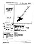
OPERATOR'S
MANUAL
THANKYOU
I,
Caiitamia Emission Regulations
Thank you for purchasing this qualily product.
This modern ootdeer power tool is designedto
provide many hours of useful service, You wllI find
it to be a great labor-saving device.
!1.
Safety Warnings ..................
A. Safety and InternatJonaI Symbols
........
3
4-7
... 6-7
II1. Assembly Instructions ................
A, Installing D-Handle ...............
B./kdluetin<_5
D-Handle ...............
C. Installing String Guard ............
8
8
t_
8
your new outdoor bower tool in top operating
condition,
IV. Oil and Fuel Information ..............
g
The othermanual that came with your power tool,
the pasts manual, contains all of the information
that you need to order parts.
V, Starting/Stoppiog Instructions ........
VI, Operating Instructions ..............
A. Adjusting Tdmmtng Une Length .....
B. Desorative Trtmming .............
This operator'smanual provides you with easy-tounderstand operatinginstructions, Read the esltra
manual and follow all of the Instructions to keep
PRODUCT REFERENCES_ ILLUSTRATIONS
AND SPECIFICATIONS
All information, illustrationsand spseificetlons
in this manual are based on the latest product
information available at the time of printing.We
reserve the right to make changesat any time
without notice,
Copyright © 1998 Ryobi Outdoor Products, Inc,
All RightsReserved.
Bump HeadTM is a trademark of Ryobi Outd_
Products,
I Service
on this unit both within and after the
I warranty period should be performed only by
| an authorized and approved service dealer.
IDial 1-800-345-8746 in the United States and
11-800-265-6778
in Information
Canada to obtain the I
Service
/listing of the authorized service dealer nearest
| you, Do not r_tum the unit to the i'_aiter.
NOTE: PROOF OF PURCHASE WtLL BE
REQUIRED FOR WARRANTY SERVICE,
VIII, Troubleshooting Chart ...............
18
IX. Specifications
19
X,
....................
Notes ...........................
XI, Warranty ........................
CONTENTS OF CARTON
l_is unit should Consist of the following:
• Modal 700r Trimmer
Q Str_ngGuard and HaY_e
• Bottle of 2-Cycle Oil
•Oparator's Manual
• Parts Manual
• Owner's RegistrationCard
THIS PRODUCT IS COVERED BY ONE OR
MOF_EOF THE US PATEt'_S LISTED SELOW;
5,076,149; 4,901,682; 4,779,405; 4,651,422;
4,505,040; 4,463,498; 4,369,742; 4,342,236;
4,223,441; 2,125,688; D-249,612; D-239,329;
OTHER PATENTS PENDING.
11
11
11
VII. Maintenanceand Repair Instructions. 12-!7
A, Maintenance Schedaie ........... 12
B. Line Installation ..................
12
1. Removing the Existing Reel ......
12
2. Winding the Existing Reel .......
!3
3. Reinstalling the Reet ...........
13
C,Installing a Prewound Reel .........
13
D. Air Filter Maintenance ............
14
E. Carboretor Adjustment ............
14
F. Replacing the Spark Plug .........
16
G.Insl:_cting the Muffler .............
16
H. Cleaning and Storage .............
17
= D-Handle and Hardware
Make sure tNs manual is casafully read and
unde_atood before starting or op_'ating this
equipment.
10
20
21
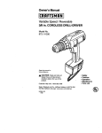
Theengine
of your
lawn and garden care product meets the 1995-1998 California emissions
regulations. These units are identified by the iabel on the engine of your product. A typical
identification label is shown.
To ensure that your unit continues to meet these regulations, refer to the following information
and instructions in this operator's manual.
RYOBI®
California Proposition 65 Warning:
IMPORTANT ENGINE INFORMATION
ENGINE DISPLACEMENT:31cc
ENGINE FAMILY: SN4031UB24RA;EM
THISENGINECONFORMSTOU.S.EPAPH1
AND1995-1998CALIFORNIA
EMISSION
REGULATIONS
FORULGEENGINES,
REFERTO OPERATOR'S
MANUALFOR
MAINTENANCE
SPECIFICATIONS
ANDADJUSTMENTS,
THE ENGINE EXHAUST FROM THIS
PRODUCT CONTAINS CHEMICALS
KNOWN TO THE STATEOF
CALIFORNIA TO CAUSE CANCER,
BIRTH DEFECTS OR OTHER
REPRODUCTIVE HARM.
NOTE: For users on U.S. Forest Land and in the states of California, Maine, Oregon and Washington.
All U.S. ForestLand andthe states of California(PubiicResourcesCodas 4442 and 4443), Oregon and
Washingtonrequire,by law that certaininternal combustionenginesoperatedon forest brushand/or grass=
coveredareas be equipped with a spark arrestor, mai_eined in effectiveworkingord_ or the enginebe
constructed,equippedand rcair_tainedfor the prev_ion of fire. Check with your stateor local authorities for
regulationspertainingto these requirements.Failureto follow these requirements could subjectyou to liability
or a fine, TIlls unit is not factory equipped with a spark arrestor. If these items are required in your area,
ask your LOCAL SERVICEdseler to install the Optional Accessory Part #1800_0 Spark Arrestor Kit.
FOR QUESTIONS, CALL 1-800-345-8746 IN U.S. OR 1-800-265-6778 in CANADA
THE PURPOSE OF SAFETY SYMBOLS
IS TO ATTRACT YOUR ATTENTION TO
POSSIBLE DANGERS. THE SAFETY
SYMBOLS, AND THE EXPLANATIONS
WITH THEM, DESERVE YOUR CAREFUL
A'i3"ENT_ONAND UNBERSTAN_NG.
THE SAFETY WARNINGS DO NOT BY
THEMSELVES ELIMINATE ANY BANGER.
THE INSTRUCTIONS OR WARNINGS THEY
GIVE ARE NOT SUBSTITUTES FOR PROPER
ACCLDBNT PREVENTION MEASURES.
SYMBOL
_ll
* IMPORTANT
_lb
warning canFailure
WARNING:
result in
to serious
obey a personal
safety
injuryto yourself or to others. Always
fenow the safety precautionsto reduse
the dsk of fire and personal injury.
A
warning mayFailureto
CAUTION:
result in obey
serLo_s_
a safety
injury to yourself or to others. Always
follow the safety precautions to reduce
the dsk of fire and pereenat injury,
NOTE:
Advises you of information or
instructions vital to the operation
or maintenance of the equipment.
SAFETY INFORMATION
READ ALL INSTRUCTIONS
•
DANGER: FaUureto obey a safety
w_ning wilt reselt in serious personal
injury to yourself or to others. Always
follow the safety precautions to reduce
the dsk of fire and personal injury,
MEANING
SAFETY ALERT SYMBOL: tndlcetee
danger, warning, or caution, Special
attention is required in order to avoid
sedous personal injury, May be used
in conjunction with other symbolsor
pictogmphs,
BEFORE
A
OPERATING
Read the instructions ceretu_y. Be laminar
with the controls and proper use of the unit.
= Children and adolescents must not
manipulate units, except for adolescents
in training and under the supervision of
a specialist.
• All guards and safety attachments must be
installed propedy befere operatingthe unit.
• Thoroughly inspect the unit for loose or
damaged parts before each use. Do not use
until adjustments or repairs are made.
"
• Always stop the engine and allow it to
cOOlbefore fillingthe fuel tank. Never
remove the cap of the fuel tank, or add
fuel, when the engine is hot.
*
P_sanre can build up in the foe( tank.
Loosen the fuel tank cap slowlyto relieve
any pressurein the tank,
• Add fuel tn a clean, wall-ventilated area.
Wipe up any spilled fuel immediately. If
fuel has been spilled, avoid creating a
source of ignition or statt_ng the engine
until fuel vapors have dissipated.
• Ensure correct fuel or fueVotl mixture is
used. Never operate the unit without the
fuel cap securely in place,
• Carefully inspect the areas to be out. Remove
all debris that could become entangled tn the
string or btade. Also remove an] _ts
that
could be thrown during cutting,
• Move the unit at least 10 ft (3 m) from the
fueling point before starting the engine.
Do not smoke, keep sparks and open
t1_nes away trom the area white adding
fuel or operating the unit,
• Be aware of the risk of injury to the head,
hands and feet.
WHILE OPERATING
SAFETY WARNINGS FOR GAS
TRIMMERS "
WARNING: Gasoline is highly flammable and
its vapors can explode if i_ited, Take the
following precautions:
• Store fuel only in containers specifically
designed and approved for the storage of
such materials.
• Weer sefsty glaases or goggles and
set/hearing protection at all times when
operating this unit. Always wear a face or
dust mask _fthe operation is dusty.
•
Dressprop_ly. Do not operate th_s unit when
barefoot or weedng open sandals, Always
wear sturdy,rubber-soled footwear, The use
. of gloves and long pants is recommended,
•
•
Do not wear loose fitting clothing or articies
such as scarves, strings, chains, ties, etc.
because they could get drawn into the air
intake. Also make sure long hair does not get
drawn into the air intake. Long hair must be
pulled back and secured off shouldersand
neck,
The stringguard must be in place at all
times whiIe operating the unit. DO NOT
OPERATE UNIT WITHOUT THE GUARD IN
PLACE.
•
Before each use, check that the string head
is correctly fixed and that the tdgger returns
automatically to the neutral posit_on.
•
Before starting, adjust the handle to your size
and make sure that the string head is not in
contact with anything.
•
Use the unit ecly in daylight or good artificial
light.
• Operate this unit onIy in a wall-vectilated
area outdoors. Carbon monoxide exhaust
fumes can be lethal in a confined area.
• Avoid accidental starting. Be in the starting
position whenever pulling the starting rope.
The operator and unit must be in a stable
position while starting, as shown in
Starting/Stopping Instructions.
•
Use the dght tool. Do not use this unit for any
job except for which it is intended.
•
Do not overreach. Keep proper footing and
balancing at all times.
• Always hold the unit with both hands when
operating. Keep a firm gdp on both the front
and rear handles or gdps,
•
•
Keep hands, face, and feet away from all
moving parts. Do not attempt to touch or
stop the string or string head when it is
rotating.
Do not touch the muffler or cylinder. These
parts get extramaly hot from operation and
remain hot for a short time after the
equipment is turned off,
•
Keep all bystanders, especialIy childran and
pets, at least 30 ft (9.1 m) away from the unit
during operation.
•
Do not operata the engine faster than the
speed necessary to cut, trim or edge. Do not
run the engine at high speed when not
cutting.
• Always stop the engine when cutting is
delayed or when walking from one cutting
location to another,
• Do not operate unit without both tdmming
Iines extended, and the proper line installed.
• Do not extend the trimming line beyond the
length of the guard as specified in this
manual.
• If you strike or become entangled with a
foreign object, stop the engine immediately
and check for damage. Repair any damage
before further operation is attempted, Do
not operate the unit with loose or damaged
parts.
• Frequently inspect the condition of the string
head, All damaged parts must be rep[eced
immediately. Follow all the required
precautions when undertaking replacement,
• All interventions, whether for maintenance,
repair or for changing string head or safety
attachments, must be undertaken with the
engine/motor stopped.
• Use only genuine replacement parts when
servicingthis unit. These parts are available
from your authorized dealer. The use of
non-standard parts, or other anceesodee or
attachments not designed for this unit,
could result in eedous injury to the user or
damage to the unit and void your warranty.
•
Keep unit clean of vegetation and other
materials. They may become {edged between
the stdng head and guard mount.
• To reduce firs hazard, replace faulty mufflers
and spark arrestors, keep the engine and
muffler free of grass, leaves, excessive
grease or carbon buildup.
OTHER SAFETY WARNINGS
• Never store the unit, w_h fuel in the tank,
inside a building where fumes may reach an
open flame or spark.
• Allow the engine to cool before storing tn an
enclosure,
• Leek up and stora the unit in an appropriate
and dry location to prevent unauthorized use
and damage.
• Keep these instructions. Refer to them
frequently and use them to instruct other
users. If you loan someone this unit, also
loan them these instructions.
SAVE THESE INSTRUCTIONS
SAFETY AND INTERNATIONAL
SYMBOLS
This operator's manual describes safety and international symbols and piotographs that may
appear on this product, Read the operator's manual for complete safety, assembly, operating
and ma'm'_enance and repair _r_ormation,
MEANING
SYMBOL
!
SAFETY ALERT SYMBOL
indicatesdanger,warning,or caution.Maybe usedin
conjunctionwithothersymbolsor pictographs.
• READ OPERATOR'S MANUAL
Failure to follow operating instructions and safety precautions
in operator's manual can result in serious injury,Read
operator's manual before starting or operating this unit,
O
• FOR SERVICE
INFORMATION,
CALL:
USA: 1-800-345-8746
CANADA: 1-800-265-6778
f!I
• WEAR EYE AND HEARING
PROTECTION
WARNING: Thrown objects and loud noise can cause severe
eye injury and hearing leas. Wear eye and ear protection when
operating this ur_t,
;•
KEEP BYSTANDERS
AWAY
WARNING: Keep all bystanders, especially children and pets,
at least 30 feet (9.1 m) away from the tdmmlng area.
5-7x
• PRIMER BULB
Pushprimer bulb,fullyandslowly,5 to 7 times.
• UNLEADED
FUEL
Always use clean, fresh unleaded fuel,
• INDICATES
OIL
Refer to operator's manual for the proper type of oil.
I-'-I
•
•
O LO.OKEposlltoo ,
PARTIALCHOKE position (B).
RUN position (C).
SYMBOL
MEANING
THROWN OBJECTS AND ROTATING CUTTER CAN
CAUSE SEVERE INJURY
WARNING:Do notoperateunitwithoutstringguardin place,
Keepaway fromrotatingstringhead.
IGNITION SWITCH
ON / START/ RUN
O
• IGNITION SWITCH
OFF OR STOP
=!
" HOT SURFACE WARNING
Do not touch a hot muffler or cylinder, You may get burned.
These parts get extremely hot from operation and remain hot
for a short time after the unit is turned off.
i
•
SHARP BLADE
WARNING: Sharp blade on string guard. To prevent serious
injury, do not touch blade,
7
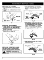
INSTALLING THE D-HANDLE
1. Push the D-handle down over the boom
(Fig. 1).
1. Place the string guard onto the boom
above the clamp assembly, so that the
guard Is In front of the string head
(Fig. 3).
2. Install the bolt, washer and wing nut and
tighten.
Grip
String
Guard
J
Assembly
Washer
Fig. 3
Rg. 1
ADJUSTING
THE
D-HANDLE
1. Loosen the wing nut. It is not necessary to
remove the wing nut, washer and bolt.
2. Rotate the D-handle so the grip is above
the top of the boom.
2. Push the string guard down to the top of
the string head assembly and then rctate
the string guard to the proper position
(Fig. 4). The string guard ts in the correct
position when the string gu_cl points
toward the engine, and the holes In the
string guard line up with the holes In the
top of the string head assembly.
3. Position the D-handle as desired and
tighten the wing nut (Fig. 2).
Fig. 4
3. Install the four (4) screws with a Phillips
screwdriver (Fig. 5).
Rg. 2
String Guard
Screw
INSTALLING
THE STRING GUARD
If the string guard on your unit is not
installed, use the following instructions.
String
Assembly
WARNING: Never operate the
trimmer without the string guard in
place.
Rg. 5
8
NOTE:
Alcohol-blended
rue{ absorbs
moisture
(water). As little as 1% moisture {n the
fuel can cause fuel and oil to separate
and form acids when stored. If alcoholblended fuel must be used, use fresh
fuel (less than 60 days old), and mix
according to the mixing instructions.
DEFINITION
OF BLENDED
FUELS
Today's fuels are often a blend of gasoline and
one
or
more
oxygenates
such
as
USE OF FUEL ADDITIVES
The use of fuel additive, such as STA-BIL®
Gas Stabilizer or an equivalent, will inhibit
corrosion and minimize the formation of gum
deposits. Add 0.8 oz (23 ml) per gallon of fuel
per instructions on container. NEVER add fuel
additives directly to the unit's fuel tank. Using
a fuel additive can keep fuel fresh for up to six
(6) months.
ethanol
methanol or MTBE (ether).
,i_
and maximum
CAUTION:
For reliability,pay
pmpar enginestrict
operation
attention to the oil and fuel mixing
instructions on the 2-cycle oil container,
Use a 32:1 fuel/o, ret_o. Use 2-cycle
oil. Using improperly mixed fuel can
severely damage the engine.
USE OF BLENDED FUELS
if you choose to use a blended fuel or its use
is unavoidable, the following precautions are
recommended.
1. Always use fresh fuel mix per your
operetor's manual.
2. Use the special additive STA-BIL® or
an equivalent,
3. Always agitate the fuel mix before fueling
the unit.
4. Drain the tank and run the engine dry
before storing the unit.
WARNING:
Gasoline
is extremely
flammable and
its vapors
can explode
if they are ignited. Always stop the
engine and allow it to cool before
filling the fuel tank. Do not smoke
while filling the tank. Keep sparks and
open flames away from the area.
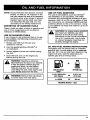
OIL AND FUEL MIXING INSTRUCTIONS
Thoroughly mix the proper ratio of unleaded
gasoline with 2-cycle engine all in a separate
fuel can, 32:1. Do not mix them directly in the
engine fuel tank. See the table below for
specific gas and oi! mixing ratios.
i
UNLEADED
GAS
RYOBI OIL
1 U.S. GALLON
(3.8 liters)
"}"
4.0 ft. oz.
(118 ml)
1 LITER
4"
30 ml
WARNING:
Remove
fuelspray.
cap slowly
to avoid injury
from fuel
MIXING RATIO - 32:1
9
(_1_
clutch unit. At idle the trimming
AUTION:
This
line
co_InueS
to model
rotate.is a non-
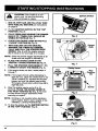
1. MIX OIL WITH GAS AND FILL FUEL TANK
WITH FUEL/OIL MIXTURE per Instructions
on page 9.
2.
Put the IGNITION SWITCH IN THE "ON"
POSITION (Fig. 6).
3.
FULLY PRESS AND RELEASE THE PRIMER
BULB 8 TO 7 TIMES, FUEL SHOULD BE
VISIBLE IN THE BULB (Fig. 7).
4,
PLACE THE CHOKE LEVER IN THE FULL
uCHOKE" POSITION (A) (F_. 8),
5.
WITH THE UNIT ON THE GROUND,
SQUEEZE THE THROI"rLE TRIGGER
FULLY AND PULL THE STARTER HOPE
BRISKLY (Fig, 9) untll the engine sounds
like it wants to run (normally2 to 5 puffs).
Switch
Rg. 6
Cap
NOTE: Keep the throttle trigger depressed at aft
times untilthe engine is wanned up.
6, PLACE THE CHOKE LEVER IN THE
"PARTIAL" CHOKE POSITION (B) (Fig. 8).
7,
PULL THE STARTER ROPE BRISKLY 1 TO
3 TIMES TO START THE ENGINE (Fig. 9).
8.
If the engine does not start, repeat steps 4
through 7,
NOTE: If the engine floods while attempting to
start the unit, place the choke [ever in the
"RUN" posiflon (C), squeeze the throttle
trigger, and pull the starter rope briskly.
The angina should statt _V_t
_n thee (3) to
eight (8) pulls,
9. Attar the angina weJ'rnsup for 5 to 10
seconds, PLACE THE CHOKE LEVER IN
THE "RUN" POSITION (C) (Fig, 8). Be sure
to keep throttle trigger depressed while
warming up engine,
NOTE: Choking is not required when starting a
warm engine, Start a warm engine in the
"PARTIAL" CHOKE POSITION (B).
10. To stop the engine, put the IGNITION SWITCH
IN THE "(WF" POSITION (Fig.6),
Fig. 7
Choke Lever
Pug
Choke
Position\
_)
"
r_k, H
P,I
Ill
,\
Partial
Choke
Position
(13)
Screw
Fig, B
Starter
Rope
ThmNie "lHgger
Fig. 9
10
Position
(C)
Run
ADJUSTING TRIMMING LINE LENGTH
Your trimmer is equipped with a bump head that
allows the operator to release more trimming
line without stopping the engine; To release
additional line, lightly tap the trimming head on
the ground (Fig, 10) while operating the trimmer
at high speed,
NOTE:
Always keep the trimming line fully
extended. Line release becomes
mote difficult as cutting line
becomes shorter,
For best results, tap the head on bare ground or
hard soil. If line release is attempted in tall grass,
the engine may stall.
,_
the
CAUTION:
line cutting
Do blade
not remove
assembly.
or altar
Excessive line length will cause
clutch to overheat and may result
tn serious personal injury.
DECORATIVE
TRIMMING
Decorative trimming is accomplished by
removing all vegetation around trees, posts,
fences, etc.
Rotate the entire unit so that the string head is
at a 30 ° angle to the ground (Fig. 11),
Rg. 10
Each time the head is bumped, about 1 in
(25,4 ram) of tdmmlng line is released. A blade
in the string guard will cut the line to the proper
length if excess line is released.
Fig. 11
11
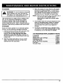
MAINTENANCE SCHEDULE
These required maintenance procedures
should be performed at the frequency stated
in the table. They should also be included as
part of any seasonal tune-up.
I_
or repairswith unit running.Always
performmaintenanceand repairson a
cool unit. Disconnectspark plug wireto
ARNING: Never performmaintenance
make sure the unit will not starL
FREQUENCY
MAINTENANCE
Daily or Before
Starting Engine
Fill fuel tank with correct oil and fuel fixture.
REQUIRED
REFER
Page 10
TO:
Every 10 Hours
Clean and re-oil air filter.
Page 14
Every 25 Hours
Inspect and clean muffler.
Pages 16-17
Every 50 Hours
Check spark plug condition and gap.
Page 16
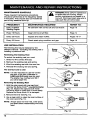
LINE INSTALLATION
The trimmlp_ line may be replaced by two
different methods - rewinding the existingreel or
installinga prewouP_ reel.
Rewinding the Exllr6ng Reel
To rewind the existing reel you must:
1. Check for the correct line size.
2. Remove the existing real and spring.
3. Wind "..heexisting ree_with the ne'_llne,
Fig. 12
4. Reinstall the existing real and spdng.
The Correct Line to Use
Outer
NOTE: It is vary Important to use the correct
size line. A line with a diameter of
0080 Inch (2.03 ram) must be used.
The ang(ne may overheat and fall if
you use a larger line,
Spool
_ang
Removing the Exlating Reel
1. Hold the outer spool with one hand and
unscrew the Bump KnobTM counterclocl,'vAse
(Fig. 12). Inspect the captured bolt Inside
the Bump Knob to make sure It moves freely.
Replace the Bump Knob if it Is damaged.
Inner
Reel
Rg. 13
2. Remove the Inner reel (Fig. 13).
3. Use a c_an cloth to clean the _ner surface of
the outer spool (Fig. 14),
NOTE: Always clean the inner real, outer spool,
and shaft before reassembling the bump
head.
Fig, 14
12
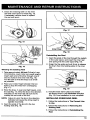
4. Check the indexingteeth on the inner
reel and outer spOOl for wear (Fig. 15).
If necessary, remove burrs or replace
the reel and spool
Inner Reel
Fig, 17
Fig,15
Fig. 18
Reinstalling the Reel
Inner
Reel
Fig. 16
1. Insert the ends of the line through the eyelets
inthe outer spool, and insert the innerreel
and spring into the outer spool (Fig, 19),
2. Grasp the line ends and pull firmly to release
the them from the holding slots in the inner
reel.
W_nding the ExisUng Reel
1. Take approxtmateJy 25 feet (7.6 m) of new
trimming line, loop it into two equaJ lengths.
insert each end of the line through one of
the two holes in the inner reel (Fig. 16).
Pull the line so that the loop is as small
as possible,
2. PlaCe your index finger betwee_ the two
lines to stop the lines from overlapping
(Fig. 17).
3. Wind the lines, in even end tight layers, onto
the reel (Fig. 17). Wind the line in the direction
indicated on the inner reel. Be surenot to
overlap the two ends of the fine.
NOTE: Failure to wind the tine in the dtrast_on
indicated will cause the string head to
operate Incorrectly.
3. Insert the ends of the line into the two
holding slots (Fig. 18).
Fig. 19
3, Hold the inner reel in place and install
the Bump Knob in the clockwise direction
(Fig. 12), Line installationis now complete.
|NSTALUNG PREWOUND REEL
1, Follow the instructions in The Correct Une
to Use,
2, Follow the instructions in Removing the
Existing Reel.
3. Follow the instructionsinReinstalling the
Reel.
13
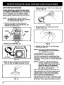
NR FILTER MAINTENANCE
CLEAN AND RE-OIL THE AIR FILTER EVERY
10 HOURS OF OPERATION. Yourunit's air filter
is one of the most important areas to maintain. If
It is not maintained,you willvoid the warranty.
Before cleaning,make sure the unitis turned off,
4, Apply enough clean SAE 30 oiI to lightlycoat
the filter (Fig. 23).
NOTE: The choke lever must be In thefull
"CHOKE" position(A) (Fig.20) to remove
and install the air filter cover.
1. Remove the scrawson each side of the
carburetor/strfilter coverassembly (Fig, 20).
Remove the air filter cover,
5. Squeeze the filter to spread and remove
excess oil (F_9.24).
Choke Le_ev
Screw_
Fig. 23
?rew
'="kl l)
Rg. 20
2. Remove the air filter (Fig. 21).
Fig. 24
6, Reinstall the filter (Fig. 21), air fiIter cover,
and screws (Fig. 20).
NOTE: If the unit is operated without '_he
carburetor/airfilter cover assembled.
you will VOID the warranty.
CARBURETOR ADJUSTMENT
AIr Filter
Rg. 21
3. Washthe filter In detergent and water (Fig. 22),
Rinsethe filter thoroughlyand alow it to dry.
This unit is equipped with a diaphragm-type
carburetor that has been carefully calibrated at
the factory. In most cases, no furtheradjustment
is requirad.
NOTE: To meet the 1995-1998 California
emission regulations, the carburetor
has adjustment needle trotter caps to
restrictthe amount of adjustment.
Removal or alterationof these caps
will voidthe unit's warranty.
Old or improperlymixed fuel are usually the
main reasons for the unit not runningpmpedy.
Drain and refillthe tank with fresh prepedy
mixed fuel pdor to making any adjustments,
Refer to OI1 and Fuel Informalion,
Rg. 22
14
The conditionof the air filter is important to the
operation of the unit, A dirty air filter will restrict
the air flow, which upsets the fuel-air mixture in
the carburetor. The resulting symptoms are often
mistaken for an out-of-adjustment carburetor.
Therefore, check the condition of the air filter
before adjusting the carburetor. Refer to Air
Rlter Maintenance.
Walbre Carburetor
Throttle
Then turn the screw in, clockwise, until it
just begins to move the throttlelever; then
continue turning 2 full
toms,
b, For Zama carburetors: Back the idle speed
screw (Fig. 26) out, counterclockwise, until it
does not contact the throftle lever. Then turn
the screw in, clockwise, until it just begins
to move the throttle]ever,then continue
turning 1-1/2 turns.
3, Initial High Speed Mixture and Idle Speed
Mixture Needle Settings: Turn both the high
speed mixture and idle speed mixture needles
out, counted'clockwise, untilthe limller caps
stop.
Idle Speed
Needle
4. Start the engine and let it run for a minute.
Fig, 25
ZamaCarburetor
Throttle
Lever
Idle S
Mixture
Needle
Needle
Fig. 26
If the following conditions are expertenced,it may
be necessary to adjustthe carburetor:
• The engine wi!l not idle
• The engine hesitstes or staUson acceleration
• A loss of engine power that is not corrected
by cleaning the air filler and muffler
NOTE: Careless adjustments can sedousiy
damage your unit. tt is recommended
that carburetor adjustments are made by
an authodzed service dealer.
Adjusting Carburetor
1. Clean the air filtar if it is dirty. Refer to Air Rlter
Maintenance.
2. Make the initial settingswith the engine
stopped. These initial
settingsshouldallowyou
to start and warm up the unit beforemaking
the final adjustments.
Initial Idle Speed Setting
a. For Waibrocarburetors:Back the idle speed
screw (Fig.25) out, counterclockwise, untilit
does not contact the carburetorthrottlelever.
5. Release the throttletdgger and let the engine
idle. If the engine stops,turn the Idle speed
screw (Rgs. 25 and 26) in, clockwise, 1/8 turn
at a time (as required) until the engineidles.
NOTE: Foming the limlter caps with a screwdriver
will damage the needle tips arv:lthe seat in
the carburetor body.
6. Final Idle Speed So'ew and Idle Speed
Mixture Needle Setting= Adjust the idle
speed screw and idle speed mixture needle
for smoothest engine idle.
a. *rumthe idle speed mixture needle (Figs.
25 and 26) in, clockwise, untilyou hear the
fastestidle; then turn the needle out,
couot;erclockwise, 1/8 turn.
b. Squeeze the throttle tdgger. If the engine
falters or hesitates as it accelerates,
turn the idle speed mixture needle out,
counterclockwise, 1/16 turn at a time
until the engine accelerates rapidly.
c. If the Idle speed changes significantly
because of Steps a and b, readjust the
Idle speed screw (refer to Step 2).
NOTE: The bump hsed/Iise spool should not
rotate when the engine idles.
Final High Speed Mixture Needle Adjusfmtent
1. High speed mixture needle adjustment is not
recommended without a precision high speed
tachometer.
2. The factory presets the high speed mixture
needle st 1-1/4 turns out from the closed
position. Your unit should perform well at this
setting. If additional adjustment of the high
speed mixture needle is required, contact your
local authorized service dealer.
15
REPLACING
THESPARK
PLUG
Use e Champion RDJ7Y spark plug (or equivalent)+
Correct air gap is 0_020 In (0,5 mm), Remove plug
after every 50 hours of operation and check Its
condition.
1+ Stop the engine and allow it to cool+Pull the
wire off of the spark plug.
Muffler Mounting Bolts
_
Exhaust
2. Clean around the spark plug and remove it from
the cylinder heed. Use a 5/8" socket to remove
the plug.
Port
Fig. 28
CAUTION:
Replace
a cracked,
or difty spark
plug. Do
not sendfouled
blast,
scrape, or clean electrodes because
the engine could be damaged by grit
entedng the cylinder,
3. Set the air gap at 0+020In (0.5 ram) using a
wire feeler gauge (Fig, 27). Install a correctly
gapped spark plug into the cylinder head.
Torque to 110-120 in,tb (12._.13.5 N,m).
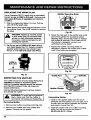
3. Check the inletpert of the muffler and outlet
port of the cylinder for excessive carbon
deposits (Figs. 29 and 30). Clean or replace
the muffler as requli3_dJ If the outlet port of
the cylinder is plugged, contact your
authorized service dealer_
4. Inspect the muffler mounting holes for
elongation, Replace the muffler and muffler
bolts if the holes are elongated.
0.6"20 In
(0.5 mm)
Fig, 29
Rg. 27
INSPECTING THE MUFFLER
_e mufflershouldbe removedevery 25 horns of
obera_n to Inspectfor excessivecarbon
build-up. Excessivedeposits around the exhaust
port (Fig+28)orexhaustholes will cause poor
engineperformance.
Outlet Port
_
Cylinder
Muffler Gasket
Use the foIldwt_gprocedure to remove, inspect,
and reinstallthe muffler.
Fig. 30
J_b
injury,make sure that the muffler is
ARNING:
To avoid serious
personal
cool
before removing
and inspecting,
Removing Muffler
1. Remove the muffler mounting bolts (Fig. 28).
2. Remove the muffler (with heat shield) and
gasket, Discard the old gasket.
16
Reinstalling Muffler
1J Install a new gasket. Make sure the arrow
stamped into the gasket is to your right. Tuck
the tab (with the arrow) between the cylinder
end plastic shroud (Fig. 30).
2. Install the muffler with the muffler mounting
bolts (Fig. 28) and torque the bolts to
80-90 in*lb (9-10.1 N,m).
CLEANING
_1
WARNING: To avoid serious personal
I
injury, always turn your trimmer off
I
and allow it to cool before you clean
or perform any maintenance on it.
Use a small brushto clsenoffthe outside of the
unit. DOnot use strong detergents on plastic
housing or handle. They canbe damaged by
household cleaners that contain aromatic oils
such as pine and lemon, and by solvents such as
kerosene. Wipe off any moisture with a soft cloth.
STORAGE
If the unit will be stored for an extended period
of time, use the following storage procedure.
1. Drain all fuel from the fuel tank and drain into
a container with the same 2-cycle fuel
mixture. 13onot use I_| that has be_
stored for more than 60 days. Dispose of
the old fueVoil mix in a safe manner and use
a fresh mix.
2. St_ the engine and allow It to run until it
stalls.This ensures that all fuel has been
drained from the cerbu_or.
3. Allow the engine to cool, Remove the spark
plug and put approximately 1 oz (30 ml) of
any high quality motor oil or 2-cycle oil into
the cylinder.Pull the starter rope slowlyto
distribute the oil. Reinstall the spark plug,
NOTE: Remove the spark plug and drain all of
the oil from the cylinder before
attempting to start the trimmer after
storage.
4. Thoroughly clean the unit and inspect for any
loose or damaged parts. Repair or replace
damaged parts and tighten loose screws,
nuts or bolts. The unit is now ready for
storage.
5. To prevant unauthorizeduse or d=m*._e of the
unit, storein a dry, wefl-vantilafed _"ea, up high
or locked up, out of the reach of children.
ACCESSOR1ESIREPLACEMEN'T
2-Cycle Oil ........................
Spark Plug ........................
ReplacementLine Cartridge...........
Replacement Une ..................
Inner Reel Spring ...................
Bump Head Knob Assembly...........
Fuel Cap..........................
Shoulder Strap .....................
PARTS
147543
610311
153577
610375
610617
153066
180000
682075
17
. .v.....,
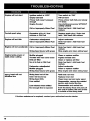
Engine will not start
"TI
l'lli'll
Ignition switch is "OFF"
Turn swltdil to "ON"
Empt_ fuet tank
Primer bulb wasn't pressed
enough
Fill fuel tank
Pines primer bulb fully and slowly
5-7 times
Engine flooded
Use starting procedure WITHOUT
USING CHOKE
Old or lmimx_perlyMixed Fuel
Drain fuel tank / Add fresh fuel
mlxtum
Fouled spark plug
Excessive oil in oil / fuel
mlxtam or Old Fuel
Replace spark plug / Drain fuel
tank / Add freah fuel mixture
Engine will not Idle
carburetor mleadjeated
Adjust _mtor
Drain fuel tank / Add fresh fuel
mixtum
Old or ImpmpeHy Mixed Fuel
Engine will not accelerate
Engine lacks power or
stalls when cutting
String head bound with grass
Drain fuel tank / Add fresh fuel
mixture
Stop engine and clean string head
Muffler plugged
Throttle wlm has come loose
Clean or replace muffler
Tighten thmtfie wire
Dirty air filter
Clean or replace air filter
No ell in fuel or Old Fuel
Drain fuel tank / Add fresh fuel
mixture
Carburetor minedjustad
Adjust carburetor
Clean or mplaea muffler
Old or Improperly Mixed Fuel
Muffler plugged
String head bound with grass
String head will not
advance line
Stop engine and clean string head
String head out of line
inner reel bound up
Refill with new line
String head dirty
Line welded
Clean inner reel and outer spool
Olsassemble, remove the welded
eactlen and rewind the line
Line twisted when refilled
Disassemble and rewind line
Not enough line is exposed
Push the Bump Knob and pull out
line until 4 Inches (102 ram) of line
is outside of the string head
Replace Inner reel
If further assistance ts required, contact your authorized service dealer.
18
ENGINE
Engir_
Type ....................................................................
Stroke ..........................................................................
Displacement .....................................................................
OperatingRPM ....................................................................
IdleSpeed RPM ...................................................................
IgnitionType ............................................................................
ignition Switch ........................................................................
Spark Rug Gap ...................................................................
l_ut_catic_ ........................................................................
FueVOilPatio ...............................................................................
C_buretor ..................................................................
Starter ..............................................................................
Muf_r .........................................................................
_ttle
......................................................................
FuelTankCapacity ...................................................................
FuelTank.........................................................................
DFUV_SHAFT& STRINGHEAID
ThrottleControl ...................................................................
OperatingWeight ..........................................................
_r
_rap ...........................................................................
Une Spool .....................................................................
IJne Spool DiaIneler..................................................................
TnmmingLine Diameter ...........................................................
Cutting PathDiameter................................................................
Air_,
2_
125 in(31.75rnm)
1.9cu. in, (3I cc)
7,000-8,200 rpm
2.800-3.600rpm
E_t¢
SlideSwitch
0.020In(0.5 ram)
FueVOilMixture
32:1
Diaphragm,
AII-pc_it_
Auto Rewind
Baffledwith Gua_
Manual Spnng Return
18 oz (530ml)
HI) Polyethylene
Finger-T=p
Trigger
Approx. 10.5Ibs(4.725kg}
O_ion_
Bump LineF_r
3 in (782 n"_ 1
0.1380in(2.03 ram)
15 in(38,1 crn)
19
CALIFORNIA EMISSION CONTROL WARRANTY STATEMENT
YOUR WARRANTY RIGHTS AND OBLIGATIONS
The Cuitfomla Air Resources Board, and Ryobi
Outdoor Produats {ROP). is pleased to explain
the emission control system warranty on your
1995 and later lawn and garden equipment
engine, in California, new lawn and garden
equipment engines must he designed, built
and equipped to meat the State's atrtsgeat
anti-smog standards. ROP must warrant the
emission control system on your lawn and
garden equipment engine for the periods of
time liatod below provided them has been no
abuse, neglect or improper maintenance of
your lawn and garden equipment engine.
MANUFACTURERIS WARRANTY COVERAGE:
The warranty pedod begins on the date the
engine or equipment is delivered to the retail
purchaser.
The manublctumr warrants to the initial owner
and each subsequent purchaser, that the
engioe is free from delfts In mstorlal and
workmanship which cause the failure of a
warranted pert for a pedod of two years.
Repair or replacement of warranted pert wig be
performed at no sharge to the owner at
e_ _z_d
Ryo'_ _e
Center. FO__
nearest location, please contact Ryobl at:
1-800-345-8746.
Your emission control system may include parts
such as the carburetor or fuel injection system,
the ignition system, and catalytic converter. Also
included may he hoses, belts, connectors and
other emiaelon_mlafod assemblies.
Any warranted pert welch is not scheduled for
replacement_ as required maintenance which is
scheduled only for regular inspection to the
effect of =Repair or rel_ace as mmessar/' Is
warranted for the warranty period. Any
warranted part which is scheduled for
replacemeat as required maintenance will be
warrantod for the pedod of time up to the ifrst
scheduled replacement point for that part.
Where a warrantable o0ndifion exists, ROP wUl
mpelr your lawn and garden equipment engine
at no cost to you including diagnosis, parts
and labor.
The t995 and later utility and lawn and garden
equipment engines are warranted for two year-=.
If any emisaion-miated part on your engine is
defective, the part will he mpuired or replaced
by ROR
OWNER'S WARRANTY
•
•
•
RESPONSIBILITIES:
As the lawn and garden equipment engine
owner, you are responsible for the
performance of the required maintenance
listed in your opemtoPs manual ROP
recommends that you r_teio all receipts
coverfng maintenance on your lawn and
garden equipment engine, but ROP cannot
deny warranty solely for the tack of receipts
or for your follme to ensure the performance
of all scheduled maintenance.
As the lawn and garden equipment engine
ovmer, you should ho_
he _
th/st
ROP may deny you warranty coverage if your
lawn and garden equipment engine or a pert
has failed due to abuse, neglect, improper
maintenance or unapproved modifications.
YOU are responsible for presenting your lawn
and garden equipment engine to a Ryobl
Authorized Service Center as soon as a
problem exists. The warranty repairs should
be completed in a reasonable amount of
time, not to exceed 30 days.
If you have any questions regardLng your
warranty rights and responsibilities, you
should call 1-800-345-6746.
The owner will not he ch_jed for diagnostic
labor welch leads to the determination that a
warranted pert is defective, If the diagnostic
work _ pedon'_nd ot a_ _nd=ed
P_tdot
Service Center.
•
The manufacbm_ Is liaMe for damages to other
engine components caused by the follum of a
wanantnd pad still under warranty.
•
Failures caused by abuse, neglect or Improper
maintenance are not covered under warranty.
•
The use of edd*on or modgiad perts can be
grounds fo_ disallowing a warranty claim. The
manatactumr is not lishia to cover fa_res or
warranted parts caused by the use of ads-on
or modified pads.
•
in order to file a r.lalm, go to your nearest
Authorized Ryobi Service Center. Warranty
se_dces o_ r_rs
_
bu proved at a_
Aatheftznd Ryeel Service Cenblrs_
•
Any manufootu_r approved replacement part
may be used in the performance of any
warranty maintenance or repair of emission
mlabld parts and win he provided without
charge to the owner. Any replacement part that
Is equivalent in performance or durability may
he used in non-warranty melntenance or repelr
and wili not reduce the warranty obligations of
the manufacturer.
The following components are included in the
emission related warranty of the e_gine, air
filter, carburetor, primer, fuel lines, fuel pick
up/fuel filter, ignition module, spark ping and
muffler.
21
LIMITED TWO-YEAR WARRANTY
BYOBI OUTDOOR PRODUCT8 warrants each new
RYOSt Product for two (2) years aesording to the
toliowing terms.
This warranty extends to the edginst rstall
purchaser only and commences on the date of
original rstall purchase.
Any part of the RYOBI Product manufactured or
supplied by RYOBI and found in the n_sonabis
judgement of RYOBI to be defective in material or
workmanship will be repaired or replaced by an
autho_ised RYOB_service dealer wltbeut charge
for parts and isbor,
The RYOBI Product ltmluding any defective part
must be returned to an authorized service dealer
within the warraractyIperiod,The expense of
dstNedsg the RYOBI Product to the dealer for
wmmnty work and the expense of returning tt
back to the owner after repair or repiscemer_ will
be paid for by the owner. RYOSFs responsibility in
respect to cialn_ is limited to making the required
repairs or replacements and no claim of breach of
warranty shall be cause for cancstistlon or
rescission of the contract of sale of any RYOBI
Product. proof of pumhese will be required by
the dealer to substantiate any warranty claim. All
warranty work must be performed by an
authorized RYOB] service deaks_
This warranty is ltmRed to ninety (90 days from the
date of oBgidal retail purchase lot any RYOB
Product thst is used for rental or commercial
purposes, or any other income-producing purpose.
This warranty does not cover any RYOBI Product
that has been subject to misuse, negisat,
negtfgence, or accident, or that has been
operated in any way contrary to the operating
instructions as specified in the RYOBI Operator'_
Manual. This warranty does not apply to any
damage to the RYOSI Product that is the result of
improper maintenance or to any RYOBI Product
that has been altered or modified so as to
adversely affect tha product's operation,
performance or durabifity or that has been
altered or modified so as to change its intended
use, The warranty does not extend to repairs
made necessary by normal wear or'by the use of
parts or accessories whish are sttber Incompadbid
with the RYOBI Product or adversely affect its
operation, performance or durabifit_
ALL IMPLIED WARRANT_BS ARE LIMITED IN
DURATION TO THE TWO (2)'_2
YEAR WARRANTY
PERIOD OR NINETY (90) DAYS FOR PRODUCTS
USED FOR ANY COMMERCIAL PURPOSE,
ACCORDINGLY, ANY SUCH IMPUED
WARRANTIES INCLUDING MERCHANTABILITY,
FITNESS FOR A PARTICULAR PURPOSE OR
OTHERWISE ARE DISCLAIMED IN THEI_
ENTIRETY ApLTERTHE EXPIRATION OF THE
APPROPRIATE TWO-YEAR OR NINETY DAY
WARRANTY PERIOD, RYOBYS OBLIGATION
UNDER THIS WARRANTY, iS STRICTLY AND
EXCLUSIVELY LIMITED TO THE REPAIR OR
REPLACEMENT OF DEFECTIVE PARTS AND
ROP DOES NOT ASSUME OR AUTHOR ZE
ANYONE TO ASSUME FOR THEM ANY OTHER
OBLIGATION, SOME STATES DO NOT ALLOW
LIMITATIONS ON HOW LONG AN IMPUED
WARRANTY LASTS SO THE ABOVE LIMITATION
MAY NOT APPLY "_6 YOU.
RYOBI ASSUMES NO RESPONSIBILITY FOR
INCIDENTAL, CONSEQUENTIAL OR OTHER
DAMAGES INCLUDING BUTNOTLIMITED
TO EXPENSE OF RETURNING THE RYOBI
PRODUCT TO AN AUTHORIZED SERVICE
DEALER AND EXPENSE OF DELIVERING IT BACK
TO THE OWNER, MECHANIC'S TRAVEL TIME
TELEPHONE OR TELEGRAM CHARGES, R EI_rAL
OF A LIKE PRODUCT DURING THE TIME
WARRANTY SERVICE IS BEING PERFORMED,
TRAVEL, LOSS OR DAMAGE TO PERSONAL
PROPERTY, LOSS OF REVENUE, LOSS OF USE
OF THE PRODUCT, LOSS OF TIME, OR
INCONVENIENCE, SOME STATES DO NOT
ALLOW THE EXCLUSION OR LIMITATION OF
INCIDENTAL OR CONSEQUENTIAL DAMAGES,
SO THE ABOVE LIMITATION OR EXCLUSION
MAY NOT APPLY TO YOU,
This warranty gives you specltk_ isgal rights, and
you may stso have other dghts which vat)"from
state to state.
This warranty applies to all RyOBI Products
manufactured by RYOBI and sold in the United
States and Canada,
To Iocateeycournearest service de_er dial
1-800-34_-8746 in the United States or
t-E00-265_6778 _n Canada.
tn addition, this warranty does not cover:
A. Tune-upe - Spark Plugs, Carburetor
Adjustments, Rlters
B. Wear items - Bump Knobs, Outer Spoals,
Cutting Line, Inner Reels, Starter Pulley,
Starter Ropes, Drive Belts
RYOSI _setves the right to change or improve
the design of any RYOBI PrOdUCt without
assumin_ any obligation to modlty any product
previousb, manufactured.
RYOaI°
RYOBI OUTDOOR
PRODUCTS
550N. 54thStreet
Chandler,
AZ85226U,S_.
RYOBI CANADA INC.
275 Ingestrial Bd
Cambridge, Ontado NIR 5K2 CANADA
SAVE THESE INSTRUCTIONS
FOR FUTURE REFERENCE.
FOR QUESTIONS CALL 1-800-345-8746
IN U.S.
OR 1-800-265-6778
IN CANADA
OPERATOR'S MANUAL PART NO, 181958
PRINTED IN U.S.A.
REV, A (7019}
3/98