1
MFJ-269C-Pro Instruction Manual
LF/HF/VHF/UHF SWR Analyzer
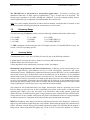
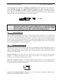
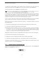
The MFJ-269C-Pro has a recessed 2.1 mm power receptacle near the RF connectors. This receptacle is
labeled POWER 13.8 VDC. The outside conductor is negative, the center is positive. Inserting a
power plug in the POWER 13.8 VDC receptacle disables internal batteries as the analyzer's power
source. However, the internal batteries will still be trickle charged when the power supply plug is
inserted into the unit. Power plugs must be wired as shown below:
+
+
-
WARNING:
2.2
2.1 mm
REVERSE POLARITY OR EXCESSIVE VOLTAGE CAN DAMAGE THE MFJ-269C-PRO.
NEVER APPLY MORE THAN 18 VOLTS, NEVER USE AC OR POSITIVE GROUND
SUPPLIES! NEVER ADD OR REMOVE BATTERIES WITH AN EXTERNAL POWER
SUPPLY CONNECTED TO THIS UNIT, OR WITH THE POWER SWITCH ON.
Internal Batteries
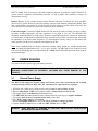
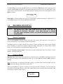
When installing internal batteries, first check the position of a small black-plastic internal jumper plug
that controls charger operation. The jumper is located inside the unit at the top of the printed circuit
board near the area of the OFF-ON switch and power connector. To access it, remove all eight screws on
the sides of the case and remove the back cover. The black plastic jumper fits over two of three adjacent
pins (see detailed instructions below). The plug must be properly positioned for the type of cell you plan
to use (AA rechargeable or AA non-rechargeable).
2.3
Rechargeable Batteries
Important Note: When using rechargeable batteries, your external power source must deliver at least 14
volts. If supply voltage is too low, the charger can't function and batteries will eventually discharge. If
batteries are depleted, charge with the analyzer power switch turned off -- it may take ten hours or more
to fully restore depleted cells.
Important Warning: Never change batteries with the power switch "On" or with an external supply
plugged in -- permanent damage may result. Always remove batteries when shipping the analyzer or
storing it for an extended period (more than a month).
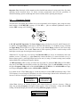
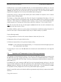
When using rechargeable batteries, the internal black plastic jumper must be set to the proper position.
Remove the analyzer cover and locate the jumper on the pc board (near the power jack). Confirm that it is
set correctly. If not, reposition as shown below:
Again, when the Charger Jumper is ON and a 13.8 to 18 volt source is applied, the charger will be
functional. Typical charging current is 10-20 mA.
5