1
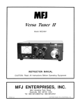
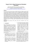
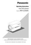
RT-100 OPERATIONS MANUAL
MANUAL REV A
LDG RT-100
100-Watt Remote
Automatic Tuner
LDG Electronics
1445 Parran Road
St. Leonard MD 20685-2903 USA
Phone: 410-586-2177
Fax: 410-586-8475
[email protected]
www.ldgelectronics.com
PAGE 1
Table Of Contents
Introduction
3
Jumpstart, or “Real hams don’t read manuals!”
3
Specifications
4
An Important Word About Power Levels
4
Important Safety Warning
4
Getting to know your RT-100
RT-100 Connections
5
6
Installation
Connections
Installing Into An Existing Outdoor Antenna Installation
Tips for Outdoor Installation
Securing the RT-100 to a Mast
7
7
8
8
10
Bias Tee Information
11
Operation
Basic Tuning Operation
Fully Automatic Memory Tuning
Force a Full Tuning Cycle
Re-tuning Prohibition
MARS/CAP Coverage
12
12
12
12
12
13
The LDG RT-100
13
A Word About Tuning Etiquette
14
Care and Maintenance
14
Technical Support
14
Two-Year Transferrable Warranty
14
Out Of Warranty Service
15
Returning Your Product For Service
15
Product Feedback
16
PAGE 2
INTRODUCTION
LDG pioneered the automatic, wide-range switched-L tuner in 1995. From its laboratories in
St. Leonard, Maryland, LDG continues to define the state of the art in this field with innovative
automatic tuners and related products for every amateur need.
Congratulations on selecting the RT-100 100-watt remote automatic tuner. The RT-100
provides full- and semi-automatic antenna tuning across the entire HF spectrum plus 6 meters, at
power levels up to 100 watts. It will tune dipoles, verticals, Yagis, or virtually any coax-fed
antenna. It will match an amazing range of antennas and impedances, far greater than some other
tuners you may have considered, including the built-in tuners on many radios.
The RT-100 is similar to previous LDG tuners, but is powered over coax, so that the tuner
element may be placed as near to the antenna as possible. The tuner element is powered over the
coax feedline by means of a built-in bias tee, so no additional cables are required in order to
place the tuner at the antenna end of the feedline. By placing the tuner as close to the antenna as
possible, SWR losses over the length of the feedline are minimized.
The optional RC-100 control unit for the RT-100 provides DC power injection via a bias tee,
as well as a convenient on/off switch, power indicator, and TUNE button, which momentarily
interrupts power to the RT-100.
JUMPSTART, OR “REAL HAMS DON’T READ MANUALS!”
Ok, but at least read this one section before operating the RT-100:
1. Turn off power to your radio.
2. Connect the antenna jack on the transceiver to the “Radio” jack on the optional RC-100 or
the “RF” jack of a bias tee (not included).
3. Connect the “Tuner” jack of the optional RC-100 or “RF+DC” jack of a bias tee to the
“Radio” jack on the RT-100, via your antenna’s existing feedline.
4. Connect the antenna to the “Ant” jack on the RT-100.
5. Connect a source of 12VDC, 500mA to the Power jack on the optional RC-100 or the bias
tee.
6. Begin transmitting; the tuner will automatically begin tuning if there is an SWR mismatch.
PAGE 3
SPECIFICATIONS
• 0.1 to 100 watts SSB and CW peak power, 30W on digital modes.
• Latching relays for ultra-low power operation.
• 2,000+ memories for instantaneous frequency and band changing.
• Power: 12VDC, 500mA, extracted from the coax feedline via built-in bias tee. (DC
injection bias tee not included)
• 1.8 to 54.0 MHz coverage.
• Tunes 4 to 800 ohm loads (16 to 150 on 6M), 16 to 3200 ohms with optional 4:1 Balun.
• For Dipoles, Verticals, Vees, Beams or any Coax Fed Antenna.
• Water-resistant case and rubber gaskets. Non-immersible.
• Operating temperature range: 0F-110F ( 18C - 43C)
• Optional external Balun allows tuning of random length, long wire or ladder line fed
antennas.
• Optional RC-100 controller provides DC power injection, On/Off switch, and Tune button.
• Dimensions: 7.0”L x 5.5”W x 3.5”H.
• Weight: 1 lb, 0 oz.
AN IMPORTANT WORD ABOUT POWER LEVELS
The RT-100 is rated at 125 watts maximum power input at most. Many ham transmitters and
transceivers, and virtually all amplifiers, are capable of transmitting well over 125 watts. Power
levels that significantly exceed specifications will definitely damage or destroy your RT-100. If
your tuner fails during overload, it could also damage your transmitter or transceiver. Be sure to
observe the specified power limitations.
IMPORTANT SAFETY WARNING
Never install antennas or transmission lines over or near power lines. You can be
seriously injured or killed if any part of the antenna, support or transmission line touches
a power line. Always follow this antenna safety rule: the distance to the nearest power
line should be at least twice the length of the longest antenna, transmission line or
support dimension.
PAGE 4
GETTING TO KNOW YOUR RT-100
Your RT-100 is a quality, precision instrument that will give you many years of outstanding
service; take a few minutes to get to know it.
The RT-100 tuner is designed to be used as a remote antenna tuner, powered over a single
coax cable that carries both the RF energy and DC power. An on-board bias tee separates the RF
from the DC power. In order to power the RT-100, a separate bias tee must be used to inject DC
power at the feed end of the coax. Alternately, the optional RC-100 Controller unit may be used.
It contains not only a DC bias tee for injecting power, but also an Off/On power button, LED
power indicator, and a Tune button which momentarily interrupts power to the RT-100.
The RT-100 is powered via 12VDC, which is supplied over the same coax cable used for the
antenna feedline. A bias tee or optional RC-100 is needed at the radio end of the cable, to inject
DC power onto the feedline. Because power is supplied over coax, the existing coax feedline to
your antenna is all you need to hook up the RT-100. No additional cables are required in order to
run power or control signals to the tuner.
The RT-100 has 2,000 frequency memories. When tuning on or near a previously tuned
frequency, the RT-100 uses “Memory Tune” to recall the previous tuning parameters in a
fraction of a second. If no memorized settings are available, the tuner runs a full tuning cycle,
storing the parameters for memory recall on subsequent tuning cycles on that frequency. In this
manner, the RT-100 “learns” as it is used, adapting to the bands and frequencies as it goes. The
RT-100’s latching relays hold the tuned configuration indefinitely, even when DC power is
completely removed. Tuning memories are stored in non-volatile FLASH memory.
PAGE 5
RT-100 Connections
The RT-100 has three connectors:
• ANT SO-239: Output to the antenna. Connect the antenna to this SO-239.
• GND (wingnut): Connect to antenna system ground.
• Radio SO-239: Connect to the feedline which comes from the optional RC-100 or bias tee.
PAGE 6
INSTALLATION
The RT-100 tuner is designed for outdoor operation; however, it is not waterproof. LDG
recommends using silicone coax sealing tape on the coax connections after installation, to ensure
water stays out of the connections. See the section on Tips for Outdoor Installation for more on
how to ensure your LDG RT-100 will give years of service outdoors.
The RT-100 is designed for use with coax-fed antennas. If use with longwires or ladder-linefed antennas is desired, an external balun is required.
Always turn your radio off before plugging or unplugging anything. The radio may be
damaged if cables are connected or disconnected while the power is on.
Connections
To install the RT-100 system, place the a bias tee in a convenient position near the
transceiver’s operating position. Connect a 50-ohm coax jumper from the transceiver’s Antenna
jack to the bias tee’s RF jack. For installation using the optional RC-100 controller, see the RC100’s user manual.
Place the RT-100 Tuner near to the antenna. Connect a short 50-ohm coax jumper from the
RT-100 Tuner’s ANT jack to the antenna. Connect the RT-100 Tuner’s RADIO jack to the bias
tee’s RF+DC jack via a length of coaxial cable feedline. LDG recommends grounding the RT100 Tuner via the wingnut marked GND.
Connect the bias tee to a source of 12VDC power, 500 mA.
NOTE: The RT-100 has no SWR display. If your transceiver does not have a built-in SWR
PAGE 7
display, you will need to put an external SWR meter in between the output of the transceiver and
the input of the bias tee:
Installing Into An Existing Outdoor Antenna Installation
The RT-100 is designed to allow you to easily upgrade your existing outdoor antenna
installation to one with a remote tuner at the antenna end of the feedline. Because the RT-100
receives its power and control signals over the coax, it is not necessary to run any additional
cables. Simply unhook the existing antenna from the antenna end of the feedline, and connect
that end of the feedline to the RT-100’s RADIO jack. Now connect a short coax jumper from the
RT-100’s ANT jack to the antenna.
At the radio end of the feedline, disconnect the feedline from the radio, and connect it to the
RF+DC jack on a bias tee. Now connect a short coax jumper from the transceiver’s TX jack to
the RF jack on the bias tee, and connect DC power.
Tips for Outdoor Installation
Although the RT-100 is water-resistant, it is not 100% waterproof. Additionally, the RT-100
should be mounted to a mast, and it should be mounted with the mounting bracket facing
upward, and the SO-239 jacks facing downward. Even if you are using the RT-100 at the base of
a vertical antenna, do not simply lay it on the ground; pound a short mast into the ground beside
PAGE 8
your vertical antenna, and mount the RT-100 to it,
with the bracket facing up, and the connectors facing
down.
In order to prevent rain water from running down
the feedline cables and into the connectors, all
connections should be wrapped with self-sealing coax
sealing tape, such as Coax Seal™ sealing tape.
Additionally, drip loops should be constructed via
coiling the coax and zip-tying it into a loop which
hangs below the connectors. The drip loop collects
any water running along the coax, and makes it drip
away from the tuner.
This technique should also be employed where
the coax cable enters the house, to prevent water
from running along the coax and into your house.
Be sure the drip loop hangs lower than the coax
entry point into the house.
PAGE 9
Securing the RT-100 to a Mast
Once the RT-100 is connected, it must be installed with the mounting bracket facing upward,
and the SO-239 connectors facing downward, to prevent rain from entering the connectors. LDG
supplies a U-bolt that permits securing the RT-100 to a mast. To secure the RT-100, first remove
the nuts and clamp from the U-bolt. Place the U-shaped threaded bolt around the mast, then slide
the clamp over the threaded ends of the U-bolt, so that the flat edge of the clamp faces away
from the mast.
Now, poke the threaded ends of the U-bolt thru the back of the mounting bracket at the top of
the RT-100. Finally, thread the nuts back onto the U-bolt, and snug them up. Tighten only as
much as is required to keep the RT-100
from sliding down the mast. Do not overtighten.
Although the U-bolt is electroplated to
resist corrosion, you may wish to apply a
thin layer of grease to the U-bolt to keep it
from rusting in the rain, to allow for easy
removal later.
If you wish to use a larger U-bolt (to bolt to a larger mast, for example) or other fastening
system, see the mounting bracket dimensions below (in inches) for sizing purposes:
PAGE 10
BIAS TEE INFORMATION
The LDG Electronics RT-100 does not come with a bias tee; it must be supplied by the
customer. While the LDG Electronics RC-100 is a perfect companion to the RT-100, and
includes a built-in bias tee designed specifically for use with the RT-100, some hams may want
to use their own bias tee.
A bias tee is a circuit which injects DC power onto the coax feedline, while isolating the DC
power from both the transmitter and the antenna. A sample schematic is shown here:
Alternatively, ready-made bias tees are available from a number of suppliers, including the
SGC 54-70 DC Coaxial Line Isolator, the Array Solutions Bias-T Master, and many others. The
only requirement is that the bias tee is rated for 1A current draw, 1.8 to 54 MHz. For more
information on bias tee construction and theory, see the Wikipedia article “Bias Tee” at
http://en.wikipedia.org/wiki/Bias_tee, ARRL’s QST article in the January 2013 issue, Vol. 97,
Issue 1, p46, or the Array Solutions Bias-T Master product review in QST, September 2009.
PAGE 11
OPERATION
Basic Tuning Operation
Two types of tuning cycles are available; a memory tuning cycle and a full tuning cycle.
The memory tuning cycle attempts to tune quickly based on having previously tuned on the
present frequency selection. If the tuner previously was successful in tuning on the currently
selected frequency, the settings for that match will be loaded into the tuner relays, and checked to
see that an acceptable SWR match is found. If this fails to find a good SWR match, then a full
tuning cycle begins.
A full tuning cycle “starts from scratch” and begins a fixed tuning sequence where the RT100 rapidly tries varying combinations of inductance and capacitance values, and then zeroes-in
on the best match possible. When the tuning cycle is complete, if an acceptable match was
found, the inductance and capacitance settings are saved in a memory associated with the
selected frequency, so that they may be recalled quickly in the future via a memory tuning cycle.
In this manner, the RT-100 “learns”; the longer you use it, the more closely it adapts itself to
the bands and frequencies used.
Whenever the RT-100 is powered up, it is in fully automatic Memory Tuning mode. This
means that any time RF is present, if the SWR detected is too high (above about 1.7), a memory
tuning cycle will automatically begin.
Most users will probably use memory tuning most of the time; it takes advantage of any
saved tuning settings, but automatically defaults to a full tuning cycle if no stored data is
available.
Fully Automatic Memory Tuning
In order to begin a fully automatic memory tuning cycle, simply tune the radio to the band
and frequency desired, and, while the RT-100 is powered on, simply being transmitting. If a high
SWR condition is detected, the RT-100 Tuner will begin tuning. To watch the progress of the
tuning cycle, keep an eye on your radio’s built-in SWR meter (or external SWR meter, if
applicable). The SWR needle will jump around for a bit and then will settle down to a low SWR
value. Once this happens, tuning is complete. If the tuner is tuning on a previously memorized
frequency, the tuning cycle will only last for a short instant while memory settings are recalled.
Force a Full Tuning Cycle
In some instances, you may wish to force the RT-100 to begin a full tuning cycle instead of
just the usual memory cycle. In order to do this, turn off power to the RT-100 (do this by
switching off power to the bias tee), begin transmitting a carrier, and while still keying the radio,
turn on power to the bias tee. Continue transmitting the tuning carrier until the SWR settles to a
low value.
When using the RC-100, transmit a carrier, press the tune button on the RC-100 for one
second then release. Continue transmitting the tuning carrier until the SWR settles to a low
value.
PAGE 12
Re-tuning Prohibition
In some rare cases, when an antenna is tuned far from its resonant frequency, the RT-100
may erroneously continue to attempt to re-tune, even though it has already found a good match
for the current antenna and frequency. In these cases, if the RT-100 decided to re-tune after it has
already found a good match, simply turn the RT-100 off, by removing power from the bias tee.
The latching relays inside the tuner will keep the current match settings even with power off, but
the tuner will stop attempting to re-tune.
MARS/CAP Coverage
The RT-100 provides continuous tuning coverage over its specified range; not just in the ham
bands. This makes it useful for MARS or CAP operation, or any other legal HF operation.
THE LDG RT-100
In 1995, LDG Electronics pioneered a new type of automatic antenna tuner. The LDG design
uses banks of fixed capacitors and inductors, switched in and out of the circuit by relays under
microprocessor control. An additional relay switches between high and low impedance ranges. A
built-in SWR sensor provides feedback; the microprocessor searches the capacitor and inductor
banks, seeking the lowest possible SWR. The tuner is a “Switched L” network, consisting of
series inductors and parallel capacitors. LDG chose the L network for its minimum number of
parts and its ability to tune unbalanced loads, such as coax-fed dipoles, verticals, Yagis, and, in
fact, virtually any coax-fed antenna.
The series inductors are switched in and out of the circuit, and the parallel capacitors are
switched to ground under microprocessor control. The high/low impedance relay switches the
capacitor bank either to the transmitter side of the inductor bank, or to the antenna side. This
allows the RT-100 to handle loads that are either greater than or less than 50 ohms. All relays are
sized to carry 100 watts continuously.
The SWR sensor is a variation of the Bruene circuit. This SWR measuring technique is used
in most dual-meter and direct-reading SWR meters. Slight modifications were made to the circuit
to provide voltages instead of currents for the analog-to-digital converters that provide signals
proportional to the forward and reflected power levels. The single-lead primary through the
center of the sensor transformer provides RF current sampling. Diodes rectify the sample and
provide a DC voltage proportional to RF power. These two voltages are read by the ADCs in the
microprocessor, and are used to compute SWR in real time.
The relays are powered by the 12VDC supplied over the coax cable via a bias tee. The bias
tee allows both RF and DC to be carried over the same conductor.
Although the microprocessor’s oscillator runs at 32 MHz, which allows the main tuning
routine to execute in only a few milliseconds, the relays require several milliseconds of settling
time for every combination of inductors and capacitors. Thus, it may take several seconds before
all relay combinations are exhausted, in the case of a difficult tune.
The tuning routine uses an algorithm to minimize the number of tuner adjustments. The
routine first de-energizes the high/low impedance relay if necessary, then individually steps
through the inductors to find a coarse match. With the best inductor selected, the tuner then steps
through the individual capacitors to find the best coarse match. If no match is found, the routine
PAGE 13
repeats the coarse tuning with the high/low impedance relay energized. The routine then fine
tunes the inductors and capacitors. The program checks LC combinations to see if a 1.5:1 or
lower SWR can be obtained, and stops when it finds a good match.
The microprocessor runs a fine tune routine just after the tuner finds a match of 1.5:1 or less.
This fine tune routine now tries to get the SWR as low as possible (not just to 1.5); it takes about
half a second to run.
A WORD ABOUT TUNING ETIQUETTE
Be sure to use a vacant frequency when tuning. With today’s crowded ham bands, this is
often difficult. However, causing interference to other hams should be avoided as much as
possible. The RT-100’s very short tuning cycle minimizes the impact of tuning transmissions.
CARE AND MAINTENANCE
The RT-100 tuner is essentially maintenance-free. Power limits in this manual should be
strictly adhered to. The outer case may be cleaned as needed with a soft cloth slightly dampened
with household cleaning solution. As with any modern electronic device, the RT-100 can be
damaged by temperature extremes, impact, or static discharge. LDG strongly recommends the
use of a good quality, properly installed lightning arrestor in the antenna lead.
TECHNICAL SUPPORT
The LDG customer support staff is ready to answer your product question by telephone and
by e-mail. We know that you will enjoy your product even more knowing LDG is ready to
answer your questions as the need arises.
LDG regularly updates on-line information so the best on-line support information is
available all day and every day.
The LDG website provides links to product manuals, just in case you lose this one! When
you are thinking about the purchase of other LDG products our website also has complete
product specifications and photographs you can use to help make your purchase decision. Don’t
forget the links to all of the quality LDG Dealers also ready to help you make that purchase
decision.
TWO-YEAR TRANSFERRABLE WARRANTY
Your product is warranted against manufacturer defects in parts and labor for two full years
from the date of purchase. This two-year warranty is also transferable. When you sell or give
away your LDG product, give the new owner a copy of the original sales receipt and the twoyear warranty goes with the new owner.
There is no need to complete a warranty card or to register an LDG product. Your product
receipt establishes eligibility for warranty service, so save that receipt. Send your receipt with the
product whenever you send your product to LDG for repair. Products sent to LDG without a
receipt are considered requests for out-of-warranty repair.
PAGE 14
LDG does not warranty against product damage or abuse. This means that a product failure,
as determined by LDG, to be caused by the customer or by other natural calamity (e.g. lightning)
is not covered under the two-year warranty. Damage can be caused by failure to heed the
product’s published limitations and specifications or by not following good Amateur practice.
OUT OF WARRANTY SERVICE
If a product fails after the warranty period, LDG wants to help you get it fixed. Send the
product to us for repair any time you like. We will determine what needs to be done and based on
your instructions, either contact you with an estimate or fix it and contact you with a request to
pay any repair charges. Please contact LDG if you have any questions before you send us an outof-warranty product for repair.
RETURNING YOUR PRODUCT FOR SERVICE
Returning a product to LDG is easy. We do not require a return merchandise authorization,
and there is no need to contact LDG to return your product. Visit the LDG web site and
download the LDG Product Repair Form. On the Repair Form tell the LDG technicians exactly
what happened or didn’t happen and why you believe the product needs servicing. The
technician attempts to duplicate the problem(s) you had based on how well you describe it so
take the time to be accurate and complete.
Ask your shipper for a tracking number or a delivery verification receipt. This way you know
the product arrived safely at LDG. Be sure to give us your email address so our shipper can alert
you online when your product is en-route back to you. Please be assured that our staff makes
every effort to complete repairs ahead of our published wait time. Your patience is appreciated.
Repairs can take six to eight weeks, but are usually faster. The most recent information on
returning products for service is found on the LDG website under Support, then Tech Support.
Send your carefully packaged unit with the Repair Form to:
LDG Electronics, Inc.
Attn: Repair Department
1445 Parran Rd
St. Leonard, MD 2068
PRODUCT FEEDBACK
We encourage product feedback! Tell us what you really think of your LDG product. In a
card, letter, or email (preferred) tell us how you used the product and how well it worked in your
application. Send along a photo or even a schematic or drawing to illustrate your narrative. We
like to share your comments with our staff, our dealers, and even other customers at the LDG
website:
http://www.ldgelectronics.com
PAGE 15