1
PCAN-cPCI
CompactPCI to CAN Interface
User Manual
PCAN-cPCI – User Manual
Products taken into account
Product Name
Model
Item Number
PCAN-cPCI Dual Channel
opto-decoupled
2 CAN channels, galvanic
isolation for CAN connections
IPEH-003021
PCAN-cPCI Quad Channel
opto-decoupled
4 CAN channels, galvanic
isolation for CAN connections
IPEH-003022
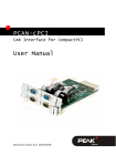
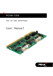
The cover picture shows the product PCAN-cPCI Quad Channel opto-decoupled. The
product version Dual Channel opto-decoupled has an identical form factor but differs
in equipment (no additional front blind with CAN connectors) and in the board's
components.
Product names mentioned in this manual may be the trademarks or registered
trademarks of their respective companies. They are not explicitly marked by “™” and
“®”.
© 2009 PEAK-System Technik GmbH
PEAK-System Technik GmbH
Otto-Roehm-Strasse 69
64293 Darmstadt
Germany
Phone: +49 (0)6151 8173-20
Fax:
+49 (0)6151 8173-29
www.peak-system.com
[email protected]
Issued 2009-02-10
2
PCAN-cPCI – User Manual
Contents
1
1.1
1.2
1.3
2
2.1
2.2
2.3
3
3.1
3.2
Introduction
4
Properties at a Glance
Prerequisites for the Operation
Scope of Supply
Installation
4
5
5
6
Installing the Software and the PCAN-cPCI
Card
Connecting the CAN Bus
Supplying External Devices via the CAN
Connector
Software
6
9
10
12
CAN Monitor PCAN-View for Windows
Linking Own Programs with PCAN-Light
12
14
4
Frequently Asked Questions (FAQ)
15
5
Technical Specifications
16
Appendix A
CE Certificate
18
Appendix B
Dimension Drawings
19
Appendix C
Quick Reference
21
3
PCAN-cPCI – User Manual
1
Introduction
The PCAN-cPCI card provides two or four CAN channels in
computers with CompactPCI slots. Software interfaces exist for
different operating systems, so programs can easily access a
connected CAN bus.
Tip: At the end of this manual (Appendix C) you can find a
Quick Reference with brief information about the installation
and operation of the PCAN-cPCI card.
1.1
Properties at a Glance
Extension card with euroboard form factor (3U) for a
CompactPCI system
According to the product version 2 or 4 High-speed CAN
channels (ISO 11898-2), CAN specifications 2.0A and 2.0B
Equipped with the CAN controller NXP SJA1000
CAN transfer rate up to 1 MBit/s
CAN connection 9-pin D-Sub male, pin assignment according to
CiA recommendation 102 DS
Galvanic isolation up to 500 V for the CAN interface, separate for
each connector
Optional 5-Volt power supply at the CAN connector for external
devices with low power consumption (e.g. bus converters)
Support for operating systems Windows and Linux
4
PCAN-cPCI – User Manual
Note: This manual describes the use of the PCAN-cPCI card
with Windows. You can find device drivers for Linux and the
corresponding application information on PEAK-System's
website under www.peak-system.com/linux.
1.2
Prerequisites for the Operation
The following prerequisites must be given, so that the PCAN-cPCI
card can be used properly:
One empty slot in the CompactPCI system, 3U form factor,
CompactPCI connector J1
With the Quad Channel version a place for an additional front
blind with CAN connectors
Operating system Windows (Vista 32 Bit, XP SP2, 2000 SP4) or
Linux (incl. 64-Bit versions)
1.3
Scope of Supply
The scope of supply normally includes the following:
PCAN-cPCI card
Front blind with D-Sub connectors for 2 CAN busses (only at
Quad Channel version IPEH-003022)
CD with software (drivers, utilities), programming examples, and
documentation
5
PCAN-cPCI – User Manual
2
Installation
This chapter deals with the software setup for the PCAN-cPCI card
under Windows, the installation of the card in the computer, and the
connection of a CAN bus.
2.1
Installing the Software and the PCANcPCI Card
We recommend that you setup the driver before installing the
PCAN-cPCI card into the computer.
Do the following to install the driver:
1.
Make sure that you are logged in as user with administrator
privileges (not needed for normal use of the PCAN-cPCI card
later on).
2.
Insert the supplied CD into the appropriate drive of the
computer. Usually a navigation program appears a few
moments later. If not, start the file Intro.exe from the root
directory of the CD.
3.
On the page English > Drivers activate the entry PCAN-cPCI.
4.
Click on Install now. The setup program for the driver is
executed.
5.
Follow the instructions of the program.
Tip: If you don't want to install the CAN monitor PCAN-View for
Windows onto hard disk together with the driver, you have the
option to start the program later directly from CD without prior
installation.
6
PCAN-cPCI – User Manual
Do the following to install the PCAN-cPCI card in the computer:
1.
At the Quad Channel version of the PCAN-cPCI card (IPEH003022) connect the cables of the additional front blind to
the 10-pin ports J1 (CAN 3) and J2 (CAN 4).
Figure 1: Positions of the pr the ports
J1 (CAN 3, lower marker) and J2 (CAN 4, upper marker)
2.
Shut down the computer.
3.
Disconnect the computer from the power supply.
4.
If applicable, remove the front blind of the CompactPCI slot
to be used in the system. The additional front blind with
connectors used by the Quad Channel version needs a
further place.
5.
Install the PCAN-cPCI card in the appropriate 3U slot (cPCI
connection J1). For details refer to the documentation of the
CompactPCI system.
6.
Place the additional connection blind beside the inserted
PCAN-cPCI card, if applicable.
7
PCAN-cPCI – User Manual
7.
Reconnect the power supply of the computer.
Do the following to complete the initialization:
1.
Turn on the computer and start Windows. Make sure again
that you are logged in as user with administrator privileges.
2.
Windows reports that new hardware has been detected and
possibly starts an installation wizard. This depends on the
used Windows version. If applicable, confirm the steps for
driver initialization.
3.
Afterwards you can work as user with restricted rights
again.
After the driver has been successfully set up you can find the entry
“PEAKCAN PCI-card” in the branch “CAN-Hardware” of the
Windows Device Manager. Concerning the software part the
CompactPCI standard is fully compatible to the PCI standard, thus
the driver for the PCAN-PCI card is used in the end.
Figure 2: Representation of the PCAN-cPCI card
in the Windows Device Manager
8
PCAN-cPCI – User Manual
2.2
Connecting the CAN Bus
A High-speed CAN bus (ISO 11898-2) is connected to the 9-pin
D-Sub connector. The pin assignment corresponds to the CiA
recommendation 102 DS.
Figure 3: Pin assignment High-speed CAN
(view onto a male D-Sub connector on the PCAN-cPCI card)
With the pins 1 and 9 devices with low power consumption (e.g. bus
converters) can be directly supplied via the CAN connector. At
delivery these pins are not assigned. You can find a detailed description in the following section 2.3.
Tip: You can connect a can bus with a different transmission
standard via a bus converter. PEAK-System offers different bus
converter modules (e.g. PCAN-TJA1054 for a Low-speed CAN
bus according to ISO 11898-3).
9
PCAN-cPCI – User Manual
2.3
Supplying External Devices via the CAN
Connector
A 5-Volt supply can optionally be routed to pin 1 and/or pin 9 of a DSub connector (independently for each connector) by setting solder
bridges on the PCAN-cPCI card. Thus devices with low power
consumption (e.g. bus converters) can be directly supplied via the
CAN connector.
When using this option the 5-Volt supply is connected to the power
supply of the computer and is not fused separately. For galvanic
isolation the measuring unit contains an interconnected DC/DC
converter. Therefore the current output is limited to 50 mA.
Attention! Risk of short circuit! If the option described in this
section is activated, you may only connect or disconnect CAN
cables or peripheral systems (e.g. bus converters) to or from
the PCAN-cPCI card while the computer is de-energized.
Set the solder bridge(s) on the card according to the desired
settings. During this procedure take especially care not to produce
unwanted short circuits on the card.
The following Figure 4 shows the positions of the solder fields on
the PCAN-cPCI card; the table below contains the possible settings.
10
PCAN-cPCI – User Manual
Figure 4: Positions of the solder fields on the PCAN-cPCI card
for a 5-Volt supply,
JP1 to JP4 for CAN channels 1 to 4
5-Volt supply →
None
Pin 1
JP1, JP2, JP3, JP4
11
Pin 9
Pin 1 + Pin 9
PCAN-cPCI – User Manual
3
Software
This chapter deals with the provided software and the software
interface to the PCAN-cPCI card.
3.1
CAN Monitor PCAN-View for Windows
PCAN-View for Windows is a simple CAN monitor for viewing and
transmitting CAN messages.
Figure 5: The main window of PCAN-View for Windows
Starting PCAN-View
You can start PCAN-View in two ways:
If PCAN-View is already installed on the hard disk, open the
Windows Start menu, go to Programs > PCAN-Hardware, and
select the entry PCAN-View PCI.
12
PCAN-cPCI – User Manual
In order to start directly from the supplied CD without prior
installation use the navigation program (Intro.exe), go to
English > Tools, and in the entry PCAN-View for PCI card click
on Start.
A dialog box for the selection of the CAN hardware as well as the
setting of the CAN parameters appears after the program start.
Figure 6: Selection of the CAN specific hardware and parameters
From the list “Available CAN hardware” select the CAN channel to
be used. Note that the count of the CAN controllers starts at 0, i.e.
the CAN controller 0 is assigned to CAN channel 1.
As a rule you can leave the remaining preset values and confirm the
dialog box with OK.
You can find further information about the use of PCAN-View in the
help which you can invoke in the program via the menu Help or the
F1 key.
13
PCAN-cPCI – User Manual
3.2
Linking Own Programs with PCAN-Light
On the provided CD you can find files for software development in
the directory branch /Develop/Windows. They exclusively serve
the linking of own programs to hardware by PEAK-System with the
help of the installed device driver under Windows.
Further more the CD-ROM contains header files and examples for
creating own applications in conjunction with the PCAN-Light
drivers. Read the detailed documentation of the interface (API) in
each header file.
You can find further information in the text and help files (file name
extensions .txt and .chm).
Notes about the License
Device drivers, the interface DLL, and further files needed for linking
are property of the PEAK-System Technik GmbH (PEAK-System)
and may be used only in connection with a hardware component
purchased from PEAK-System or one of its partners. If a CAN
hardware component of third party suppliers should be compatible
to one of PEAK-System, then you are not allowed to use or to pass
on the driver software of PEAK-System.
PEAK-System assumes no liability and no support for the PCANLight driver software and the necessary interface files. If third party
suppliers develop software based on the PCAN-Light driver and
problems occur during use of this software, please, consult the
software provider. To obtain development support, you need to
own a PCAN-Developer or PCAN-Evaluation license.
14
PCAN-cPCI – User Manual
4
Frequently Asked Questions
(FAQ)
Question
Answer
Do I need to install the
device driver for each
existing CAN channel
under Windows?
No. A single installation procedure is
sufficient. In the Windows Device
Manager a single device entry appears
under CAN-Hardware, however, in
PCAN applications all CAN channels are
available automatically.
Does each CAN channel No. All available versions of the PCANcPCI card only use a single interrupt in
use an interrupt?
the computer. However, each CAN
channel is assigned to a different port
address.
Can I use several PCAN- Yes. A one-time installation of the
cPCI cards in the same device driver is sufficient in this case,
too.
computer?
Instead of a High-speed
CAN bus I would like to
connect another one
(e.g. Low-speed CAN).
Is this possible?
Yes. You need a bus converter to do so.
PEAK-System offers bus converter
modules for different transmission
standards that are plugged between the
PCAN-cPCI card and the CAN bus.
15
PCAN-cPCI – User Manual
5
Technical Specifications
Connectors
Computer
CompactPCI connector J1 (110 Pin, 32 Bits)
CAN
D-Sub (m), 9 pins, pin assignment according to CiA
recommendation 102 DS
Galvanic isolation up to 500 V (separate for each CAN
connector)
CAN
Specification
ISO 11898-2
High-speed CAN (up to 1 MBit/s)
2.0A (standard format) and 2.0B (extended format)
Controller
NXP SJA1000T
Transceiver
NXP PCA82C251T
Supply
Current consumption
External devices at the
CAN connector (Pin 1/9)
IPEH-003021 (Dual Channel):
V)
IPEH-003022 (Quad Channel):
V)
max. 490 mA (5
max. 980 mA (5
5 V, max. 50 mA per CAN connector, activated with
solder bridges
Measures
Form factor
CompactPCI 3U plug-in card
Dimension
Board:
160 x 100 mm (6 5/16 x 3 15/16 inches)
Total:
175 x 130 mm (6 7/8 x 5 1/8 inches, without
locking lever)
(See also dimension drawing in Appendix B on page
19)
Weight
IPEH-003021 (Dual Ch. opto-dec.):
120 g (4.23 oz.)
IPEH-003022 (Quad Ch. opto-dec., 132 g + 56 g
plus connection blind):
(4.66 oz. + 1.98 oz.)
Continued on the next page
16
PCAN-cPCI – User Manual
Environment
Operating temperature
-40 – +85 °C (-40 – +185 °F)
Temperature for storage
and transport
-40 – +125 °C (-40 – +257 °F)
Relative humidity
15 – 90 %, not condensing
EMC
EN 55024:2003-10
EN 55022:2007-04
EC directive 2004/108/EG
17
PCAN-cPCI – User Manual
Appendix A
CE Certificate
18
PCAN-cPCI – User Manual
Appendix B
Dimension Drawings
Figure 7: Top view PCAN-cPCI card
19
PCAN-cPCI – User Manual
Figure 8: View of the front blind
The figures don't show the original size.
20
PCAN-cPCI – User Manual
Appendix C
Quick Reference
Software/Hardware Installation under Windows
Before installing the PCAN-cPCI card into the computer please set
up the corresponding software package from the supplied CD (with
administrator privileges). Afterwards, insert the PCAN-cPCI card into
an empty CompactPCI slot of the switched off (de-energized)
computer. At the next start of Windows the PCAN-cPCI card is
recognized by Windows and the driver is initialized. After the driver
has been successfully installed you can find the entry “PEAKCAN
PCI-card” in the branch “CAN-Hardware” of the Windows Device
Manager. Afterwards, you may also work as user with restricted
rights.
Getting Started under Windows
Run the CAN monitor PCAN-View from the Windows Start menu as
a sample application for accessing the PCAN-cPCI card. Select the
desired channel. The preset parameters for initialization of the card
can be used without changes.
High-speed CAN connector (D-Sub, 9 pins)
21