1
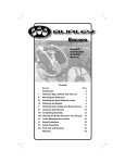
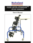
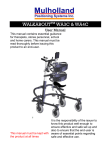
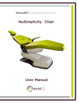
ROCKET STANDER 1 & 2
Use r s Manual
1
TABLE OF CONTENTS
2
Preface
3
Design Goals
3
Precautions
3
Components
4
Assembly
5-8
Adjustment Overview
9
Fitting Instructions
10
Main Column Adjustment
10-11
Tray Adjustment
12
Knee Block Adjustment
13
Foot Support Adjustment
14
Folding the Stander
15
Optional Configurations
16-21
Supine Stander
16-17
Neckrest Support System (Prone)
18-19
Shoulder Pad Assembly
20-21
Placing the Child in the Stander
22
Maintenance
22
Technical Data
23
PREFACE
This instruction manual provides information to professionals for the set
up and use of the Rocket Stander. Supported standing can stimulate headrighting, weight-bearing on the forearms, and mid-line hand use. Standing
also provides an opportunity for peer socialization and upper extremity
activities, which should be an integral part of a standing program.
DESIGN GOALS
The Rocket Stander was designed to provide individuals requiring prone,
vertical, or supine standing, precise postural control at the upper trunk,
pelvis, knees, and ankles. Adjustment from prone to vertical to supine
offers therapists the opportunity to provide graduated weight-bearing to
promote more normal tone distribution and stability, and selective
extension of the spine.
PRECAUTIONS
1. Standing should always be prescribed by the child s physician with
recommendations for duration of standing, frequency and
contraindications. The standing program should be closely monitored
by the child s therapist.
2. The stander should be used under direct adult supervision at all times.
3. Do not use for transportation.
4. Use stander only on level surfaces.
5. Observe load limits on product label.
3
COMPONENTS
Refer to figure 1.
1.
2.
3.
4.
5.
6.
Sternum Pad
Tray Assembly
Main Column
Tilt Trigger
Locking Castors
Tilt Bar
7. Shoe/Foot Supports
8. Folding Strap
9. Knee Support
10.Upper Column
11.Hip Support
12.Trunk Support
1
2
12
11
3
10
4
9
8
5
7
Figure 1
4
6
ASSEMBLY
Tools Required:
5/32 , 3/16 , 1/4 allen wrenches (included in the pouch)
Tape measure
Adjustment Levers:
Refer to figure 2.
The adjustment levers can be ratcheted so the
handle can rotate without affecting the
tightness of the screw.
1. Pull up lever to disengage.
2. Rotate the handle so it is not obstructed.
3. Release and let the handle slide back and
lock with the screw.
4. Continue tightening/loosening the screw
by rotating the handle and repeating steps
1-3 as needed.
Figure 2
Ball Lock Pins:
Refer to figure 3.
1. Hold the head of the pin between your
index and middle finger.
2. Press in on the blue button with your
thumb while extracting (or inserting)
the pin.
Figure 3
1
Hand Knobs:
Refer to figure 4.
1. Release (unlock) the knob by turning
it counter-clockwise.
2. Lock the knob by turning it clockwise.
Figure 4
5
Step A: Prepare for Assembly
Refer to figure 5.
Lay the components out on the floor.
You should have received the following
for a basic system:
1. Base
2. Upper Column
3. Tray
4. Two Knee Supports
5. Foot Support
Figure 5
C2
Figure 7
Step B: Assembly the Base
Refer to figures 6 & 7.
1. Pull up on the main column until the
tilt mechanism slides in between the
black markings.
2. Tighten the two allen screws that
secure the tilt bar to the main
column.
3. Swing the legs away from each other
Figure 6
until they lock into place.
Note: The main column is correctly
aligned if it is vertical when the base is
standing on the floor.
6
Figure 7
C1
Step C: Insert the Upper Column
Refer to figure 8
1. Remove the allen screw from the bottom
part of the upper column.
2. Slide the upper column down into the main
column.
3. Line up the holes in the upper and main
columns (1), and tighten the adjustment
lever to secure.
4. Insert the allen screw
(1) and tighten.
2
1
Figure 8
Step D: Attaching the Knee Blocks
and Foot Supports
Refer to figure 9.
1. Slide the Knee Blocks into their
respective brackets and secure with
the adjustment levers. The vertical
adjustment levers should be facing
outward.
2. Slide the foot supports onto the
bottom of the column, and secure
by tightening the two allen screws
(1).
1
Figure 9
7
Step E: Attaching the tray
Refer to figure 10.
1. Release the hand knobs (1)
on the ends of the tray
mounting bar.
2. Place the tray assembly on
the tray mounting bar so
the teeth on the angle locks
(2) mesh.
3. Lock the cams to secure
the tray by turning the
hand knobs (1) clockwise
until tight.
8
Figure 10
2
1
ADJUSTMENT OVERVIEW
The separate and combined adjustments are critical to the effectiveness of
the Rocket Stander. The therapist is encouraged to try various adjustment
combinations to find the optimal position for weight-bearing, tonal
balance, and head-righting. It is further recommended that an on-going
adjustment schedule be identified to meet the needs of physical growth,
reduction, or increase in postural support and weight-bearing activities.
Adjustments:
1. Column Tilt (Pitch):
Affects the child s orientation in space, postural tone and distribution
of weight. After the column tilt adjustment has been made, always
replace the ball lock pin, so as to not accidentally release the trigger.
2. Hip and Trunk Support:
Provide not only lateral, but also anterior/posterior support. The hip
support should always be snug. The trunk support can be graded to
allow for lateral movement as the child acquires increased trunk
control.
3. Knee Supports:
Knee blocks provide not only anterior support, but can also change in
angle to accommodate flexion at the knees.
4. Foot Supports:
The foot supports are independently adjustable to provide equal weight
bearing through both lower extremities. They can be adjusted to
compensate for leg length discrepancy, plantarflexion/dorsiflexion,
rotation, and hip abduction.
5. Tray Height:
Tray height adjustment can provide an upper extremities weightbearing surface (for table top activities) and can also assist in head
control (by stabilizing the shoulder girdle through forearm support).
The tray is pitch adjustable and reversible for supine standing.
See the following pages for specific adjustments and fitting
instructions.
9
FITTING INSTRUCTIONS
Measurements:
The following measurements are required for proper fitting:
1. Heel to the iliac crest (hip bone): _______
This will be the distance from the footplates to the top of the hip
support on the stander.
2. Heel to axilla (under arm): _______
The distance from the footplates to the top of the trunk support on the
stander.
3. Heel to the lowest point on the patella (knee cap): _______
The distance from the footplates to the middle of the knee block.
4. Hip width (widest part): _______
The exact width of the hip support.
5. Trunk width: _______
Usually the exact trunk support width, but may be looser if the child
has good trunk control.
6. Leg length discrepancy: _______
The distance the individual foot support must be lowered on the longer
side.
MAIN COLUMN ADJUSTMENT
Refer to figure 11. For measurements see Fitting Instructions.
Note: Never make any adjustments with the child in the stander.
1. Keep the hip support (A) as close to the frame pivot point as possible.
This is extremely important! This is done by loosening the 4 allen
screws and sliding the hip support next to the frame junction support.
Retighten the screws.
2. Measure from the top of the hip support to the foot supports, then
loosening the 2 screws, lower or raise the foot support to the correct
height. Retighten the screws.
3. Measure from the foot supports to the middle of the knee block (C).
Adjust the knee blocks to the correct height. Retighten the screws.
4. Measure from the foot supports to the top of the trunk support (D) and
adjust the height. If more height is required, loosen the adjustment
lever (F) and extend the column. Retighten the screws.
5. Very lightly loosen the 4 screws on the trunk support (to not disturb the
10
height adjustment), and adjust the width. Tighten firmly. Repeat for the
hip support.
6. Pitch: remove the ball lock pin (E) on the trigger tilt by pushing in on
the black button as you pull out. Squeeze the trigger to adjust the pitch
of your column. Replace the ball lock pin!
7. Adjust the knee block angle.
8. Adjust the angle of the foot supports. Remember that if the hips and
knees are flexed to 10 degrees, the foot supports must be plantarflexed
10 degrees to give neutral alignment at the ankles. This is very
important for children with limited range.
Figure 11
11
TRAY ADJUSTMENT
Refer to figure 12.
1. Height: Loosen the two allen screws (1) and slide the tray along the
upper column to the desired height. Tighten the screws.
2. Depth: Loosen the two knobs (2), located underneath the tray. Slide the
tray along the tray bar to the desired depth. Tighten the knobs.
3. Angle: Release both hand knobs (3). Rotate the tray about the tray
mounting bar to the desired angle. Make sure the teeth on the angle
locks mesh. Tighten the hand knobs.
Figure 12
1
3
12
2
KNEE BLOCK ADJUSTMENT
Refer to figure 13.
1. Angle: Loosen the adjustment lever (1). Rotate the knee support bar (2)
until the knee pad is at the appropriate angle to support the knees.
Tighten the lever. Repeat for both sides.
2. Depth: Loosen the adjustment lever (1). Slide the knee support bar
until the knee pad is at the correct width to assist in the alignment of
the lower extremities. Tighten the lever. Repeat for both sides.
3. Height: Loosen adjustment lever (3). Slide the knee pad along the knee
support bar to make small height adjustments. Tighten the lever. Repeat
for both sides.
4. For additional height adjustment: Loosen levers (1) and rotate the knee
support bar 180°. Tighten the lever. Loosen lever (3), then remove the
knee blocks and replace them right side up. Slide the knee blocks to the
desired position then tighten the levers.
5. Width: Loosen the two allen screws (4). Slide the knee block along the
knee block bar (5) to the desired width. Tighten the screws. Repeat for
both sides.
Figure 13
3
4
2
5
1
13
FOOT SUPPORT ADJUSTMENT
Refer to figure 14.
1. Leg length discrepancy: Loosen the allen screw (1), the outer screw on
the mounting bracket, for the shoe holder which needs to be lowered.
Lower the shoe holder, by lowering the shoe holder support bar (2), to
accommodate the lower leg. Tighten the screw.
2. Abduction: Loosen the screws (3), located on the footrest mounting
brackets underneath the shoe holders. Adjust the width between the
shoe holders by sliding them along the footrest bars (4). Note:
Excessive abduction may cause increased weight-bearing on the medial
borders of the feet. Tighten the screws.
3. Plantarflexion/Dorsiflexion: Loosen the screws (3). Rotate the shoe
holders about the footrest bar. Tighten the screws.
4. Rotation: Loosen both flat head screws (5) on the top of the shoe
holder. Pivot the shoe holder about the rear flat head screw. Tighten the
screws. Repeat for both shoe holders.
5. Depth: Loosen the allen screw (6). Slide the foot support along the
support bar. Tighten the screw. Repeat for both shoe holders.
Figure 14
1
5
6
2
4
3
14
FOLDING THE STANDER
Refer to figures 15 & 16.
1. Tilt the stander column, by removing the ball lock pin first then
squeezing the trigger, until the column is vertical.
2. Remove or lower the tray.
3. With one hand, hold on to the top of the column and tilt the stander up
on to the front wheels (1). With your other hand, squeeze the frame
lock pins (2), and tilting the frame forward, allow the back frame to
swing to the front frame. Secure with the strap (3).
Figure 15
2
1
Figure 16
3
15
OPTIONAL CONFIGURATIONS
Always remove the child from the stander before alterations are made.
Supine Stander
Convert to supine:
Figure 22
1. Replace the sternum pad with the
supine neckrest assembly (refer to
figures 23-25):
a) Loosen the adjustment lever
(1). Slide the sternum pad
assembly off the upper
column.
b) Attach the supine neckrest by
sliding the track stud (2) into
the front track of the upper
column.
c) Tighten the adjustment lever
(3), on the neckrest assembly,
to secure the neckrest. The
track stud must be completely within the front track.
d) Adjust the height of the neckrest: Loosen the adjustment lever (3).
Slide the assembly along the upper column to the desired height.
Tighten the lever.
e) Adjust the depth of the neckrest: Loosen the two allen screws (4).
Slide the neckrest back/forth to the desired depth. Tighten both
4
2
3
1
Figure 23
16
Figure 24
Figure 25
screws.
2. Move the tray (refer to figures
26):
a) Release both hand knobs (1)
then lift the tray off the tray
mounting bar.
1
b) Replace the tray on the
opposite side of the upper
column.
c) Retighten the hand knobs to
lock the tray in place.
d) The tray must be removed to
place the child in the supine
stander.
3. Move the foot supports (refer to
figure 27):
c) Loosen the four allen screws
(6). Slide the foot supports off
the footrest bars.
d) Rotate the foot supports to
face the opposite direction.
e) Replace the foot supports on
the footrest bars.
f) Tighten the four allen screws
to secure the foot supports.
Figure 26
6
6
Figure 27
17
Neckrest Support System (Prone):
Attaching the prone neckrest support system:
Refer to figure 28 & 29.
1. Remove the upper column:
a) Unscrew the safety screw
from the column (see Step
E in the assembly
instructions for details).
b) Loosen the adjustment
lever on the main column.
c) Slide the upper column up
and out of the main
column.
2. Add the neckrest support
system:
a) Loosen the two allen
screws (1), located on the
side of the neckrest bar
clamp.
b) Slide the neckrest bar
clamps onto the main
column.
c) Tighten the two screws.
3. Replace the upper column:
a) Slide the upper column back into the main column.
b) Tighten the adjustment lever on the main column.
1
Figure 29
18
Figure 28
Adjustments:
Refer to figure 30.
5
3
1. Neckrest assembly height:
a) Loosen the two allen screws (figure 29.1).
b) Slide the neckrest bar clamps along the
4
main column to the desired height.
c) Tighten the screws.
2. Neckrest assembly depth:
a) Adjustment lever (2), located at the
bottom of the neckrest post.
b) Slide the neckrest support to the desired
location.
c) Tighten the adjustment lever.
3. Height of the neckrest:
a) Loosen the two allen screws (3), on the
2
side of the ear clamp.
b) Slide the neckrest along the hex bar (4) to
Figure 30
the desired height.
c) Tighten the screws.
4. Depth of the neckrest:
a) Loosen the two allen screws (3).
b) Slide the neckrest ears (5) back/forth to the desired depth.
c) Tighten the screws.
5. The neckrest support system can be moved out of the way while
placing the child in or removing the child from the stander. Loosen
adjustment lever (2) and slide the neckrest support out of the way.
Reverse procedure to return post to vertical position.
19
Shoulder Pad Assembly:
Attaching the shoulder pad assembly.
Refer to figure 31.
1. Remove the neckrest from the neckrest bar (1): Loosen the two allen
screws (2) on the ear clamp. Slide the neckrest off the neckrest bar.
2. Add the shoulder pad assembly: Loosen the allen screw (3) located on
the side of the cross bar bracket (4). Slide the cross bar bracket onto the
neckrest bar. Tighten the allen screw.
3. Replace the neckrest: Slide the neckrest onto the neckrest bar by
placing the neckrest bar between
the ear clamps. Tighten the two
2
allen screws (2).
Adjustments:
Refer to figure 31 & 32
20
1. Height: Loosen the allen screw
(3). Slide the cross bar bracket
along the neckrest bar to the
desired height. Tighten the screw.
2. Depth: Loosen the bar clamp (5)
by loosening the allen screw (6)
3
on the top. Loosen the lock pin
block (7) by loosening the allen
screw (8) on the side. Slide the
shoulder pad back/forth to the
depth which provides the
appropriate amount of anterior
support. Align the lock pin
block, with the plunger pin (9) on
top so the shoulder pad will lock
in position when in use and when
pivoted out of the way. Tighten
the allen screw (8) to secure the
lock pin block. Slide the bar
clamp against the pivot pin
receiver (10) to provide enough
tension to lock the pivot. Tighten
1
4
2
Figure 31
7
10
5
3
12
8
6
11
Figure 32
the allen screw (6) to tighten the bar clamp. Repeat for both sides.
3. Width: Loosen the set screw (11) on the bottom of the pivot pin
receiver. Slide the receiver along the hex bar (12) to the desired width.
Tighten the set screw. Repeat for both sides.
4. Pivoting the shoulder pads: The shoulder pads can be released and
pivoted out of the way while placing the child in or removing the child
from the stander. Pull the ring on the back of the plunger pin to release
the pivot. To open, rotate the shoulder pad away from the column until
the pivot locks. Repeat for both sides. To replace, pull the ring and
rotate the shoulder pad in the opposite direction until the pivot locks.
21
PLACING THE CHILD IN THE STANDER
1. Always lock the casters on the stander before putting the child into it.
2. The child s therapist should identify whether one or two people are
required to transfer the child to the stander.
3. Place the child s feet into the shoe holders and slowly lift him into
standing.
4. Fasten the hip strap (velcro) first, then the trunk strap (velcro).
5. Check for proper alignment and weight bearing.
6. Fasten the buckle straps on the hip and trunk supports, the buckle
straps for the shoe holder, and the velcro straps on the knee supports.
7. The child should be under direct adult supervision at all times.
8. Provide a table top or socialization activity while the child is standing.
9. Observe the child closely for signs of fatigue, distress, or discomfort.
10.Remove the child within the prescribed time period.
MAINTENANCE
1. Keep the stander clean. The metal and plastic parts can be washed with
a mild concentration of dish soap (the same as you use on your dishes).
Rinse with water and dry. Wipe down all of the upholstered parts with
a damp cloth.
2. Check weekly for frayed straps and velcro, which may need
replacement. For the child s safety, discontinue use of the stander until
worn velcro and straps are replaced.
22
TECHNICAL DATA
Specifications:
Rocket 1
Rocket 2
Weight Limit:
Height Range:
Length:
Width:
Frame Color:
50 lbs (23 kg)
24-41 (61-104 cm)
26 (66 cm)
22 (56 cm)
Corvel Red
(Morton 40-4023)
Black
75 lbs (34 kg)
36-50 (91-127 cm)
32 (81 cm)
22 (56cm)
Corvel Red
(Morton 40-4023)
Black
Upholstery Color:
Materials:
Frame:
Parts:
Padding:
Fabric:
Castors:
Drive Wheels:
Powder-coated aluminum tube
Black anodized aluminum extrusion
Stainless steel tube
Powder-coated aluminum
Black anodized aluminum
Black ABS plastic, flame retardant
Clear Plexiglas acrylic
Neoprene foam
Nylon packcloth
Naugahyde (US393)
Solid gray cushion rubber with delrin bearing
Grey pneumatic tire on nylon rims with double seal
ball bearings
23
839 Albion Ave
P.O. Box 70
Burley, ID 83318
Phone: (208) 878-3840
(800) 543-4769
Fax: (208) 878-3841
[email protected]
www.mulhollandinc.com
24