1
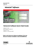
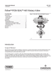
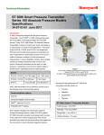
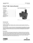
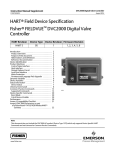
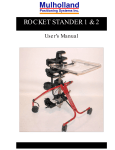
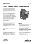
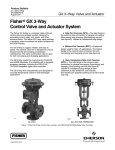
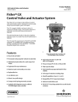
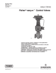
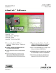
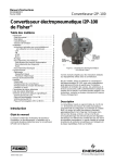
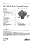
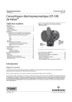
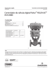
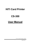
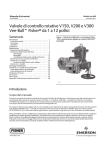
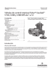
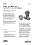
Product Flier
PF51.3:Vee-Ball
D102429X012
May 2009
High-Capacity Rotary Valves
Fisher High-Capacity Rotary
Valves for General or Fibrous
Slurry Service
W9415
Figure 1. Fisher High-Capacity Rotary Valve
Rotary valve efficiency with globe valve ruggedness for general gas, steam, or liquid
service and for fibrous slurry applications
DN 25 to DN 300 and NPS 1 to 24 x 20
Choice of seal types and materials—composition, flat metal, heavy-duty metal, or
flow ring
Temperatures to 427C
Pressures to PN40 and CL600
ENVIRO-SEAL packing systems to help ensure compliance with environmental
emissions requirements
FIELDVUE digital valve controllers offer digital control and remote diagnostics. The
proven line of Fisher positioners, controllers, transmitters, and switches also is
available.
www.Fisher.com
Product Flier
PF51.3:Vee-Ball
May 2009
High-Capacity Rotary Valves
The Fisher Vee-Ball Valve Family
Vee-Ball rotary valves combine the features and
performance you need. These features are made
available through expertise in applications, valve
design, and manufacturing.
The valves are suitable for throttling or on-off
service. They are often used with a full 0 to 90
degree ball rotation.
Fisher V150, V200, and V300 Vee-Ball valves use
the time-proven V-notch ball that provides
high-capacity control of liquid, gas, steam, and
fibrous slurries. The shearing action of the ball
allows smooth, non-clogging operation, and the
unrestricted, straight-through flow ensures high
capacity.
Easy Installation . . . Fisher V150 and V300 integral
flanges eliminate exposed flange studs, and the
V200 features line-centering lugs to simplify
alignment.
High Rangeability . . . Flow coefficient ratio is 300
to 1.
Reduced Maintenance Costs . . . The V150, V200,
and V300 valves have interchangeable trim parts to
reduce spare parts inventory and cost and simplify
maintenance procedures and training. Metal and soft
seals are interchangeable within a valve body.
Protection Against Process Fluid Emissions . . .
Optional ENVIRO-SEAL packing systems provide an
excellent shaft seal to prevent the loss of valuable or
hazardous process fluids. These live-loaded
systems provide long packing life and reliability.
Materials for Sour Service . . . Emerson Process
Management offers materials and manufacturing
procedures for compliance with NACE (National
Association of Corrosion Engineers) standard NACE
MR01752002, MR0103, and MR0175 / ISO 15156.
2
W74351/IL
Figure 2. Fisher V150 or V300 Valves
Easy Seal Inspection . . . Seals can be inspected
without removing the actuator or disassembling the
valve.
Noise Attenuator Ball. . . Depending on service
conditions, up to -10dBA acoustical attenuation and
a KC of 1.0 for liquid flow are possible with the noise
attenuator ball (available with DN 100 through DN
300 and NPS 4 through 20 valves).
Basis Weight Control Valve . . . Fisher V150,
V200, and V300 valves are available to meet the
precision control requirements of basis weight
control in the paper-making industry.
Other Rotary Products
Fisher V500 Valve . . . The V500 valve uses rugged
valve components and a choice of erosion-resistant
trim materials for highly erosive and severe
operating conditions at pressures to PN 100 (CL600)
and temperatures to 538C.
Fisher CV500 Valve . . . The CV500 combines the
rangeability of the cammed-segmented V-notched
ball, with the inherent ruggedness found in the V500
heavy duty bearings, seals and body. This
combination provides a balance of high capacity,
erosion resistance, and pressure control for liquid
and gas.
Product Flier
PF51.3:Vee-Ball
May 2009
High-Capacity Rotary Valves
The Fisher Vee-Ball Valve Family (Continued)
Other Rotary Products (Continued)
Fisher V250 . . . The V250 valve is a heavy-duty
valve often used in gas transmission lines, gas
distribution, or liquid pipelines. It is available in sizes
to NPS 24 and CL600 or CL900
pressure-temperature ratings.
PACKING STUD
PACKING NUT
O-RING
PACKING
FOLLOWER
O-RING
Fisher V260 . . . The V260 valve has special
energy-dissipating trim to reduce noise effects that
cause pipeline vibrations. It is available in NPS 8,
10, 12, 16, 20, and 24 sizes.
PACKING
SET
PACKING BOX
RING
14B9917-B
E0735 / IL
Fisher Control-Disk Valve . . . This rotary valve
with an equal percentage flow characteristic
provides an improved throttling range. This improved
capability allows you to control closer to the target
set point, regardless of process disturbances. This
capability results in a reduction in process variability.
LEAK-OFF PACKING ASSEMBLY
FOR NPS 1 THROUGH 12 VALVES
Fisher 8532, 8580, and 8510/8510B . . . This family
of high performance butterfly valves is designed for
optimal control performance, as well as tight shutoff
isolation service. These valves are available in size
range NPS 2 to 24 and a variety of pressure classes
and body styles.
Fisher A11 . . . The POSISEAL A11
high-performance butterfly valves are designed for
optimal control performance as well as tight shutoff
for isolation, automated on/off service. These valves
feature square, keyed, or splined shafts. These
valves are designed for use in highpressure,
hightemperature, or cryogenic applications, and
available in sizes NPS 3 through 72, and pressure
classes up to CL2500.
W7557-1/IL
ENVIRO-SEAL PACKING SYSTEM
(SINGLE PTFE V-RING)
Figure 3. Optional Rotary Valve Packing Assemblies
W7555/IL
W5393
Vee-Ball VALVE BALL WITH ATTENUATOR
BASIS WEIGHT VALVE AND ACTUATOR
Figure 4. Attenuator and Basis Weight Valve
3
Product Flier
PF51.3:Vee-Ball
May 2009
High-Capacity Rotary Valves
Selecting Vee-Ball Products
Only a few of the more commonly selected product materials,
sizes, options, and accessories are covered in this flier.
Contact your Emerson Process Management sales office (refer
to the back cover) for assistance in selecting and sizing these
products. More detailed specifications are available on request.
Selecting Valve Components
Valve Type Selection . . . . . . . . . . . . . . . . . . . . . . . . . . . . . . . 5
Body Materials, End Connections, and Ratings . . . . . . . . . 7
Valve Component Materials and Temperatures . . . . . . . . . 7
Selecting an Actuator
Fisher 2052 Diaphragm Actuator . . . . . . . . . . . . . . . . . . . . . 8
Fisher 1051 and 1052 Diaphragm Actuators . . . . . . . . . . . 9
Fisher 1061 Piston Actuator . . . . . . . . . . . . . . . . . . . . . . . . 10
Selecting Valve Instrumentation and Accessories
Fisher FIELDVUE Digital Valve Controllers . . . . . . . . . . .
Fisher 3610J Valve Positioners . . . . . . . . . . . . . . . . . . . . . .
Other Accessories . . . . . . . . . . . . . . . . . . . . . . . . . . . . . . . . .
Reference Information
Maximum Inlet Pressure for CW2M Valve Bodies . . . . . .
Shutoff Pressure Drop Limits for Trim Parts . . . . . . . . . . .
Flow Coefficients . . . . . . . . . . . . . . . . . . . . . . . . . . . . . . . . . .
Actuator-Valve Selection (Shutoff Pressure Drops) . . . .
Approximate Weights . . . . . . . . . . . . . . . . . . . . . . . . . . . . . .
Dimensions . . . . . . . . . . . . . . . . . . . . . . . . . . . . . . . . . . . . . . .
Emerson Process Management Sales Offices . . . . . . . .
4
11
13
14
15
15
16
17
21
22
24
Product Flier
PF51.3:Vee-Ball
May 2009
High-Capacity Rotary Valves
Fisher Vee-Ball Valves
W7435/IL
W5787/IL
W7435/IL
V150 VALVE
V300 VALVE
V200 VALVE
Figure 5. Fisher Vee-Ball Valves
Table 1. Vee-Ball Valves
V150
V200
V300
Applications
Excellent for fibrous slurries as well as liquids,
gas, and steam. Shearing V-notch ball for
smooth, non-clogging action.
Excellent for fibrous slurries as well as liquids,
gas, and steam. Shearing V-notch ball for
smooth, non-clogging action.
V150: DN 25 - 500 or NPS 1 - 24 x 20
NPS 1, 1-1/2, 2, 3, 4, 6, 8, 10
Excellent for fibrous slurries as well as liquids,
gas, and steam. Shearing V-notch ball for
smooth, non-clogging action.
Sizes
DN 25 - 500 or NPS 1 - 20
Ratings
V150: PN 10/16 or CL150
CL150, CL300, or CL600 depending on size.
PN 25/40 or CL300
End Connections
Raised-face (RF) flanged
Flangeless
Raised-face (RF) flanged
EN: 1.0619 steel, 1.4409 stainless steel, M35-1,
or CW2M
ASME: SA216 WCC steel, SA351 CF3M, CF8M
stainless steel, M35-1, or CW2M
Valve Body Materials
EN: 1.0619 steel, 1.4409 stainless steel, M35-1,
or CW2M
ASME: SA216 WCC steel, SA351 CF3M, CF8M
stainless steel, M35-1, or CW2M
Ball Material
EN: 1.0619 steel, 1.4409 stainless steel, M35-1,
or CW2M
ASME: SA216 WCC steel, SA351 CF3M,
CG8M stainless steel M35-1, or CW2M
SA351 CF3M, or CG8M, CG8M stainless steel,
CW2M
SA351 CF3M or CG8M stainless steel, CW2M
SA351 CF3M, or CG8M stainless steel, CW2M
TCM Plus, metal (S31600), HD (heavy duty)
metal, or flow ring
TCM Plus, metal (S31600), HD (heavy duty)
metal, or flow ring
Seal Types
TCM Plus, metal (S31600), HD (heavy duty)
metal, or flow ring
Flow Characteristics and Maximum Flow Coefficients
Modified equal percentage
Maximum Cv from 3.64 to 10,300
Modified equal percentage
Maximum Cv from 8.4 to 3000
300 to 1
300 to 1
Modified equal percentage
Maximum Cv from 8.4 to 10,300
Rangeability
300 to 1
Shutoff Class
Composition Seal: Class VI
Metal Seal: Class IV
Flow Ring Construction: 5% of wide-open
capacity
Composition Seal: Class VI
Metal Seal: Class IV
Flow Ring Construction: 5% of wide-open
capacity
Available Actuators (refer to page 8)
Composition Seal: Class VI
Metal Seal: Class IV
Flow Ring Construction: 5% of wide-open
capacity
Fisher 2052, 1051, 1052, 1061, and FieldQ
Fisher 2052, 1051, 1052, 1061, and FieldQ
Fisher 2052, 1051, 1052, 1061, and FieldQ
5
Product Flier
PF51.3:Vee-Ball
May 2009
High-Capacity Rotary Valves
Fisher Actuators
W9589-1/IL
W3813/IL
2052 ACTUATOR
W3827/IL
1061 ACTUATOR
1051 AND 1052 ACTUATORS
Figure 6. Fisher Rotary Valve Actuators
Table 2. Fisher Rotary Valve Actuators
2052
1051 AND 1052
1061
Features
Heavy-duty actuator with enclosed linkage and splined actuator-valve connection for minimized lost motion
Style
Spring-return pneumatic diaphragm actuator
Spring-return pneumatic diaphragm actuator
Double-acting pneumatic piston actuator
Typical Operating Torque Range (Varies with Operating Pressure and Construction)
50.8 to 565 Nm
85 to 1370 Nm
282 to 19,800 Nm
Accessories
Pneumatic or electro-pneumatic valve positioners, FIELDVUE digital valve controllers, limit switches, position transmitters, handwheels, travel stops,
lock-out device to disable actuator during maintenance, supply pressure filter-regulator.
6
Product Flier
PF51.3:Vee-Ball
May 2009
High-Capacity Rotary Valves
Valve Component Materials and Temperatures
Table 3. Valve Component Materials and Temperatures
BODY, SHAFT, AND BALL (TEMPERATURE IS DETERMINED BY OTHER PARTS LISTED BELOW)
CF3M (316L stainless steel), DIN 1.0619 steel, WCC steel, or
CG8M (317 stainless steel)
Valve Body
S20910 or S17400 (17-4PH stainless steel)
Valve Shaft
V-Notch Ball
CF3M (316L stainless steel), chromium-plated CF3M, CG8M (317 stainless steel), or
chromium-plated CG8M
SEAL, BEARING, AND PACKING
MAXIMUM
TEMPERATURE, C
PTFE
Graphite
V-Ring
Packing
Packing
SEAL MATERIAL
BEARING MATERIAL
Composition (TCM plus)
PEEK (poly-ether-ether-ketone)/PTFE,
R30006 (alloy 6B) or silver-plated
R30006
232
232
Flat metal—(spring-tempered stainless steel)
(available on DN 80 through 300
[NPS 3 through 12] only)
HD (heavy-duty) metal
( CF10SMnN or
CD7MCuN [alloy 255 duplex stainless
steel], or R30006
Flow ring (steel or stainless to match
body material)
PEEK/PTFE
232
260
R30006, silver-plated R30006, or
S31600L (316L stainless steel) nitride
232
427
PEEK/PTFE
232
260
R30006, silver-plated R30006, or
S31600L nitride
232
288
PEEK/PTFE
232
260
232
427
R30006, silver-plated R30006, or
S31600L nitride
OTHER PARTS
MATERIAL
MAXIMUM
TEMPERATURE, C
PTFE
Graphite
V-Ring
Packing
Packing
N07750 and PTFE with
N10276
Chromium-plated CG8M or solid alloy 6
Temperature is
determined by parts listed
above
PART
Wave spring and radial seal (HD metal only)
Micro-notch V-notch ball for DN 25 (NPS 1)
Solid VTC ceramic
Gasket
Graphite
Optional line bolting
B7, B7M, or strain-hardened B8M
W6197-1*
W5704-1/IL
COMPOSITION SEAL
93
NOTES
Minimum temperature
for DIN valve bodies is
10C
Minimum temperature
for ASME constructions
is 29C for steel
valves and 46C for
stainless steel valves
Contact your
Emerson Process
Management sales
office for
ENVIRO-SEAL packing
temperatures and
pressures
Contact your
Emerson Process
Management sales
office for pressure
drops and temperatures
with TCM-Ultra
composition seal.
93
Temperature is
determined by parts listed
above
W4713-3/IL
HD (HEAVY-DUTY) METAL SEAL
FLAT METAL SEAL
Figure 7. Fisher Vee-Ball Seals
7
Product Flier
PF51.3:Vee-Ball
May 2009
High-Capacity Rotary Valves
Fisher 2052 Diaphragm Actuators
The 2052 pneumatic diaphragm rotary actuators are
compact, spring-return actuators that provide reliable
operation for the valves in this flier.
The 2052 actuator mountings conform to ISO 5211;
the actuator can be mounted directly to non-spline
shafts, such as square or double-D, allowing the
actuator to be paired with a wider range of valves to
be used for both automated on/off and throttling
applications.
This actuator features single-joint linkage with
splined-and-clamped levers for minimum lost motion
and high control accuracy.
W9588-1/IL
W9589/IL
It also features a nested spring design, which
requires no bench set, simplifying the actuator
selection process.
Figure 8. Fisher 2052 Actuator
Accessories . . . Pneumatic and
electro-pneumatic positioners, FIELDVUE digital
valve controllers, and Limit and proximity
switches.
Options . . . Top-mounted handwheel, Fisher
1078 declutchable handwheel actuator, and actuator locking mechanism
Table 4 .Fisher 2052 Actuator Specifications
2052
ACTUATOR
SIZE
1
2
3
8
NOMINAL OPERATING
PRESSURE RATINGS
MAXIMUM CASING
PRESSURE
MAXIMUM
VALVE
BREAKOUT
TORQUE, Nm
Bar
Psig
Bar
Psig
2-3
30-43
5.0
73
28
4-5
60-72
5.0
73
50.8
2-3
30-43
5.0
73
104
4-5
60-72
5.0
73
209
2-3
30-43
5.0
73
270
4-5
60-72
5.0
73
565
AMBIENT
TEMPERATURE, qC
40 to 80
MATERIALS
Upper Casing: Steel
Housing: Cast Iron
Diaphragm: Nitrile and nylon is
standard; silicone and polyester
low-temperature is optional
Lever: Ductile iron
Diaphragm Plate: Cast iron
Product Flier
PF51.3:Vee-Ball
May 2009
High-Capacity Rotary Valves
Fisher 1051 and 1052 Diaphragm Actuators
The 1051 and 1052 pneumatic diaphragm rotary
actuators are spring-return actuators that provide
reliable operation for the valves in this flier.
The 1051 actuator is suitable for on-off operation or
for throttling operation when equipped with a valve
controller or positioner. The 1052 actuator is suitable
for on-off or throttling with or without a controller or
positioner.
These actuators feature single-joint linkage with
splined-and-clamped levers for minimum lost motion
and high control accuracy. The actuator-valve
linkage is completely enclosed for safety, yet the
packing adjustment is accessible without removing
any parts.
W3813-1/IL
Figure 9. Fisher 1051 Actuator
Specifications . . . Refer to the table below and the
actuator selection tables.
Options . . . Top-mounted handwheel, 1078
declutchable handwheel actuator, Adjustable upand down-travel stops, Actuator locking
mechanism that keeps the actuator in a locked
position during maintenance, and Pipe-away vent
for remote venting of the actuator housing.
Accessories . . . Pneumatic and
electro-pneumatic valve positioners, FIELDVUE
digital valve controllers, and Limit and proximity
switches.
Table 5. Fisher 1051 Actuator Specifications
1051
1052
Bar
Psig
1051
33
33
40
40
0 to 1.2,0 to 2.3,
0 to 2.8, and
0 to 3.8
0 to 18, 0 to 33,
0 to 40, and
0 to 55
60
60
0 to 1.2,
0 to 2.3,
and 0 to 2.8
0 to 11, 0 to 33,
and 0 to 40
---
70
0 to 2.3,
0 to 2.8,
and 0 to 3.8
0 to 33, 0 to 40,
and 0 to 55
---
1052
1051
1052
4.5
85
132
5.2
322
371
3.4
626
730
---
1370
4.5
AMBIENT
TEMPERATURES,
C
MATERIALS
Diaphragm: Nitrile
(standard) or silicone
O-rings (for optional
handwheel): Nitrile or
Nitrile: 40 to 82
EPDM
Silicone: 50 to 149
Housing: Cast iron
(standard) or steel
Other Major Metal
Parts: Aluminum, steel,
or cast iron
W4742-1/IL
Figure 10. Fisher 1052 Actuator, Size 33
9
Product Flier
PF51.3:Vee-Ball
May 2009
High-Capacity Rotary Valves
Fisher 1061 Piston Actuators
The 1061 pneumatic rotary actuators are
double-acting piston actuators that provide reliable
operation for the valves in this flier.
The 1061 can be used with a two-position control
signal for on-off operation or with a valve controller
or positioner for throttling operation.
These actuators feature single-joint linkage with
splined-and-clamped levers for minimum lost motion
and high control accuracy.
The actuator-valve linkage is completely enclosed
for safety, yet the packing adjustment is accessible
without removing any parts.
Specifications . . . Refer to the table below and the
actuator selection tables.
W3827-1/IL
Figure 11. Fisher 1061 Actuator
Options . . . 1078 declutchable handwheel
actuator with cylinder bypass valve, Adjustable
up- and down-travel stops, Actuator locking
mechanism that keeps the actuator in a locked
position during maintenance, and Pipe-away vent
for remote venting of the actuator housing.
Accessories . . . Pneumatic and
electro-pneumatic valve positioners and Limit and
proximity switches.
Table 6. Fisher 1061 Actuator Specifications
ACTUATOR
SIZE
Minimum
Recommended
Maximum Allowable
MAXIMUM VALVE
BREAKOUT
TORQUE, Nm
30
6.9
232
40
10.3
847
60
Without positioner: 1.4
With positioner: 0.35 bar
above actuator requirement
6.9
1130
5.9
1540
80
10.3
5080
100
10.3
6290
68
10
CYLINDER OPERATING PRESSURE, BAR
AMBIENT
TEMPERATURES,
C
MATERIALS
34 to 82
(to 50 with optional
materials)
Cylinder and flange: Aluminum
Piston: Aluminum or nylon-coated
aluminum
O-rings: Nitrile
Mounting yoke bushing: PTFE
and steel
Sliding seal: Brass
Other parts: Iron, aluminum, and
stainless steel
Product Flier
PF51.3:Vee-Ball
May 2009
High-Capacity Rotary Valves
FIELDVUE Digital Valve Controllers
W8755
DVC2000
W9418
DVC6000 on Control-Disk VALVE
Figure 12. Fisher Digital Valve Controllers
FIELDVUE digital valve controllers are
communicating, microprocessor-based controllers
that convert a current signal to a pressure signal to
operate the actuator. Through digital
communications, the controller gives easy access to
actuator-valve information that is critical to operation.
Refer to following tables for FIELDVUE controller
specifications.
AMS ValveLink Software . . . AMS ValveLink
Software allows easy access to the information
available from FIELDVUE digital valve controllers.
The software provides diagnostic information such
as dynamic error band and step response on
easy-to-interpret screens. Tests can be run while the
valve is operating, without disrupting the process.
Access to diagnostics is through the 375 Field
Communicator or a personal computer using AMS
ValveLink Software.
Options (contact your Emerson Process
Management sales office for details on product
specific options) . . . HART, FOUNDATION
fieldbus, remote mounting, stainless steel
housing, Safety Instrumented System (SIS)
applications, Natural gas applications,
Performance Diagnostics, extreme
temperatures, and low bleed relay.
Approvals Available
Not all approvals are available on all FIELDVUE
products. Contact your Emerson Process
Management sales office for specific approvals.
Explosion proof, Division 2, Dust-Ignition
proof, Intrinsic Safety, Non-incentive
APPROVED
Explosion proof, Non-incendive,
Dust-Ignition proof, Intrinsic Safety
ATEX Flameproof, Type n, Intrinsic Safety
IECEx Flameproof, Type n, Intrinsic Safety
Flameproof, Intrinsic Safety
Flameproof, Intrinsic Safety
Fisher DVC2000 Electrical Housing: Designed to
meet IP66 (FM--approval pending for other
agencies) NEMA 4X (approval pending). Contact
your Emerson Process Management sales office for
information on pending approvals.
Fisher DVC6000 and DVC6000f Electrical
Housing: Meets NEMA 4X, CSA Type 4X, IEC
60529 IP66
Natural Gas Approved: The DVC6000 and
DVC6000f are single-seal approved for use with
natural gas. Contact your Emerson Process
Management sales office for specific agency
approval information.
11
Product Flier
PF51.3:Vee-Ball
May 2009
High-Capacity Rotary Valves
FIELDVUE Digital Valve Controllers (Continued)
Table 7. Digital Valve Controller Electrical Specifications (HARTr instruments Only)
Analog Input
Signal
4 to 20 mA DC
nominal
ELECTRICAL INPUT
POINT-TO-POINT CONNECTION
Minimum Current
Minimum
without
Maximum
Control
Microprocessor
Voltage
Current
Restart
4.0 mA
3.5 mA
30 VDC
Overcurrent
Protection
Input circuit limits
current to prevent
internal damage
MULTI-DROP
CONNECTION
(DVC6000 ONLY)
INSTRUMENT
POWER
REVERSE
POLARITY
PROTECTION
11 to 30 VDC at
approximately 8 mA
No damage occurs
from reversal of loop
current
Table 8. Digital Valve Controller Electrical Specifications (FOUNDATIONt fieldbus Communication only)
POWER REQUIREMENTS
COMMUNICATION PROTOCOL
FOUNDATION fieldbus registered device
Physical Layer Type(s):
121—Low-power signaling, bus-powered, Entity Model I.S.
511—Low-power signaling, bus-powered, FISCO I.S.
12
Voltage Level
Maximum
Current
Reverse
Polarity
Protection
Termination
9 to 32 volts
18 mA
Device is not
polarity sensitive
Bus must be properly
terminated per
ISA SP50 guidelines
Product Flier
PF51.3:Vee-Ball
May 2009
High-Capacity Rotary Valves
Valve Positioners
Fisher 3610J, 3610JP, and 3620JP Valve Positioners
The 3610J single-acting pneumatic, 3610JP
double-acting pneumatic, and 3620JP double-acting
elector-pneumatic valve positioners are accurate,
efficient positioners for use with 1051, 1052, 1061
actuators.
Approvals Available
Electrical Classification (Applies to the 3620JP)
Intrinsic Safety, Explosion proof, Type
n Dust-Ignition proof, DIV 2,
Intrinsic Safety, Explosion proof, Type
n, Non-incendive, Dust-Ignition proof,
ATEX
Intrinsic Safety, Type n, Flameproof
(Gas Atmospheres Only),
IECEx
Intrinsic Safety, Type n, Flameproof,
(Gas Atmospheres Only),
INMETRO Intrinsic Safety, Flameproof
APPROVED
W8693-1/IL
Hazardous Area Classifications
The 3610J and 3620J valve positioners comply
with the requirements of ATEX Group II Category
2 Gas and Dust
Figure 13. Fisher 3610J Pneumatic Valve Positioner and
i2p-100 Electro-Pneumatic Transducer with 1052 Actuator
and V300 Valve
Table 9. Fisher 3610J and 3620J Positioner Specifications
Type
3610J and
3610JP
3620J and
3620JP
Input Signal
0.2 to 1.0 or
0.4 to 2.0 bar
3 to 15 or
6 to 30 psig
4 to 20 mA constant current with 30
VDC maximum compliance voltage;
equivalent circuit is 120 ohms
shunted by three 5.6 V zener diodes
Supply Pressure
Operative
Temperature
Weight
0.3 bar above the
actuator requirement
up to 10.3 bar
maximum
40 to 80C
2.5 kg
0.3 bar above the
actuator requirement
up to 10.3 bar
maximum
40 to 80C
3.6 kg
Connections
Pressure and Vent
Connections: 1/4 NPT
3620J and JP Conduit: 1/2
NPT
Table 10. Fisher 3610J and 3620J Capacities and Housing
Type
3610J and 3620J
3610JP and 3620JP
Supply Pressure, Bar
Supply Air Demand,
Nm3/h
Air Consumption, Nm3/h
Housing (3620J and
3620JP)
1.4
13
2.4
17
3610J: 0.40 to 1.4 bar supply
3620J: 0.49 at 1.4 bar supply
5.2
37
6.9
46
IP 54 per IEC 529
classification
(weatherproof), NEMA 3;
vent should be on the
side or bottom for
weatherproof applications
3610JP: 0.64 at 6.9 bar supply
3620JP: 0.93 at 6.9 bar supply
13
Product Flier
PF51.3:Vee-Ball
May 2009
High-Capacity Rotary Valves
Other Accessories
Fisher 67CFR Filter-Regulator . . . The 67CFR
provides constantly controlled supply pressure to
actuator accessories system. This regulator features
an internal filter and limited-capacity internal relief,
allowing partial reduction of downstream pressure.
Also featured is a Smart Bleed option that allows the
actuated valve to fail to a desired safe position when
inlet pressure is lost.
Table 11. Fisher 67CFR Filter-Regulator Specifications
OUTLET PRESSURE
SETTINGS
Bar
Psig
0 to 1.4
0 to 2.4
0 to 4.1
0 to 8.6
0 to 20
0 to 35
0 to 60
0 to 125
MAXIMUM
INLET
PRESSURE
(BODY
RATING), BAR
17.2
MAXIMUM
DIAPHRAGM
PRESSURE,
BAR
TEMPERATURE
CAPABILITIES,
C
CONNECTIONS
MAXIMUM
FLOW
COEFFICIENT,
CV
WEIGHT,
kg
3.4 over outlet
setting
Nitrile diaphragm
and plug: -29 to 82
Fluorocarbon
diaphragm, plug
and PVDF, SST, or
Glass Filter: -18 to
149
Inlet and Outlet:
1/4 NPT internal
Vent: Drilled hole or
1/4 NPT internal
0.36
0.5
Fisher 546, 646, 846, or i2P-100 ElectroPneumatic Transducers . . . These transducers
convert a standard 4 to 20 mA DC signal to a
proportional pneumatic signal. The 846 and i2P-100
transducers incorporate an explosive fluid process
seal to meet safety regulations for use with natural
gas as the pneumatic supply.
INMETRO
Intrinsic Safety, Flameproof
GOST Intrinsic Safety, Flameproof, and Type n
Fisher 2625 Volume Booster . . . The volume
booster can be used in conjunction with a positioner
to increase actuator stroking speed.
Approvals Available
Not all approvals are available on all accessories.
Contact your Emerson Process Management sales
office for specific approvals.
Explosion proof, Division 2, Dust-Ignition
proof, Intrinsic Safety, Type n
APPROVED
Explosion proof, Intrinsic Safety,
Non-incendive, Dust-Ignition proof, Type n
ATEX Intrinsic Safety, Flameproof, and Type n
IECEx Intrinsic Safety, Flameproof, and Type n
14
Fisher C1 Pneumatic Controller . . . The controller
can sense pressure, differential pressure or vacuum
and send pneumatic control signal to an adjacent
valve or other control element.
Others . . . High-pressure supply pressure
regulators, proximity switches, microswitches,
solenoid valves, signal volume boosters and pneumatic pressure transmitters.
Contact your Emerson Process Management sales
office for more information.
Product Flier
PF51.3:Vee-Ball
May 2009
High-Capacity Rotary Valves
Maximum Inlet Pressure for CW2M Valve Bodies
Table 12. Maximum Inlet Pressure for CW2M Valve Bodies
TEMPERATURE, C
MAXIMUM INLET PRESSURE,
BAR
150
300
600
46 to 38
93
149
204
232
20.0
17.9
15.9
13.8
12.8
51.7
51.7
50.3
48.6
47.2
NOTE
CW2M is not listed in ASME
B16.34. The designations 150, 300,
and 600 indicate relative
pressure-retaining capabilities and
are not ASME
pressure-temperature rating
classes.
103
103
100
97.2
94.5
Shutoff Pressure Drop Limits for Trim Parts
the EN or ASME pressure-temperature rating of
the valve or mating flanges, as exceeding the
pressure-temperature rating may cause personal
injury or equipment damage.
WARNING
Pressure drops in the following table consider
only the trim parts (ball, shafts, bearings, and
seals).
In the following tables, the lower temperature limit is
10C for EN valves, 29C for ASME steel valves,
and 46C for ASME stainless steel valves.
The pressure drops shown might be higher than
the EN or ASME pressuretemperature rating of
the valve body or mating flanges. Do not exceed
Also refer to the actuator sizing pages to select an
actuator size.
Table 13. Pressure Drop in Bar (For HD Metal Seal, Pressure Drops are for Forward Flow Only. For Reverse HD Seal Flow, Limit
Pressure Drop to 6.9 Bar)
VALVE SIZE
BEARING
MATERIAL
1
1-1/2
2
3
4
6
8
10
12
-46 to 38
DN
25
51.0
DN
40
51.0
DN
50
51.0
DN
80
51.0
DN
100
51.0
DN
150
51.0
DN
200
51.0
DN
250
40.2
DN
300
37.6
14
16
20
---
---
---
93
37.9
37.9
37.9
37.9
37.9
37.9
37.9
37.9
37.6
31.0
23.8
31.0
31.0
23.8
149
24.1
24.1
24.1
24.1
24.1
24.1
24.1
24.1
31.0
24.1
24.1
23.8
204
10.3
10.3
10.3
10.3
10.3
10.3
10.3
24.1
10.3
10.3
10.3
10.3
232
3.45
3.45
3.45
3.45
3.45
3.45
10.3
3.45
3.45
3.45
3.45
3.45
HD Metal
-46 to 288
51.0
51.0
51.0
51.0
51.0
3.45
51.0
51.0
40.9
38.1
40.3
26.5
Flat Metal
-29 to 260
---
---
---
20.7
40.3
20.7
20.7
20.7
10.3
10.3
---
---
Flow Ring
---
99.3
99.3
99.3
99.3
---
72.4
75.2
73.8
40.5
37.7
40.5
35.0
44.7
HD Metal
-46 to 288
51.0
50.0
25.7
Flat Metal
-29 to 260
---
---
---
17.5
11.0
10.9
11.2
6.14
5.72
6.14
7.52
6.83
17.0
10.1
10.7
10.6
5.86
5.52
---
---
Flow Ring
---
74.5
49.6
---
26.8
18.8
10.9
11.2
11.1
6.07
5.65
6.07
7.31
6.69
HD Metal
-46 to 288
51.0
Flat Metal
-29 to 260
---
51.0
51.0
35.0
22.1
21.8
22.5
12.3
11.4
12.3
13.2
13.7
---
---
20.7
20.1
20.7
20.7
10.3
10.3
---
---
Flow Ring
---
---
99.3
99.3
53.5
37.6
21.8
22.5
22.2
12.1
11.3
12.1
14.6
13.4
HD Metal
Flat Metal
-46 to 288
51.0
51.0
51.0
---
---
---
---
---
---
20.5
13.2
14.0
-29 to 260
---
---
---
---
---
---
---
---
---
---
---
---
Flow Ring
---
99.3
99.3
88.9
---
---
---
---
---
---
20.2
20.1
22.3
HD Metal
-46 to 288
---
---
---
51.0
36.7
36.3
37.4
20.5
19.1
---
---
---
Flat Metal
-29 to 260
---
---
---
20.7
20.7
20.7
20.7
10.3
10.3
---
---
---
Flow Ring
---
---
---
---
62.7
36.3
37.4
37.0
20.2
18.8
---
---
---
BALL SEAL
TCM Plus
PEEK/PTFE
R30006
R30006
Silver Plated
S44004
S31600L
Nitride
TEMPERATURE,
C
15
Product Flier
PF51.3:Vee-Ball
May 2009
High-Capacity Rotary Valves
Flow Coefficients
Table 14. Fisher V150, V200, and V300 (Forward Flow)
VALVE SIZE
VALVE ROTATION, DEGREES (LINE SIZE EQUALS VALVE SIZE)
10
30
60
90
10
30
Cv
60
90
10
30
Kv
60
90
10
60
90
.571
.548
.585
.628
.507
.516
.559
.501
.275
.328
.366
.302
.697
.574
.526
.219
.792
.770
.735
.735
.518
.518
.537
.473
.221
.200
.176
.189
.63
.37
.37
.73
.366
.999
.273
.999
.632
.605
.566
.605
.490
.593
.452
.593
.245
.198
.133
.198
DN
NPS
25(1)
40(1)
50(1)
80
1(1)
1-1/2(1)
2(1)
3
.0098
.014
.028
.746
2.53
6.15
9.60
27.7
12.4
27.8
46.1
120
34.6
76.0
123
321
.0085
.012
.024
.645
2.19
5.32
8.30
24.0
10.7
24.0
39.9
104
29.9
65.7
106
278
.93
.87
.94
.91
.90
.86
.90
.88
.84
.82
.83
.80
.69
.73
.75
.74
.392
.492
.386
.664
100
150
200
250
4
6
8
10
3.56
5.34
6.99
43.5
47.2
82.1
122
252
195
340
518
1000
596
1100
1820
3000
3.08
4.62
6.05
37.6
40.8
71.0
106
218
169
294
448
865
516
952
1570
2600
.88
.93
.89
.85
.90
.91
.90
.88
.80
.80
.82
.80
.62
.58
.54
.56
300
-------
12
14
16
20
44.2
60.0
70.0
110
390
541
692
993
1530
1670
2380
3070
3980
5610
8270
10,300
38.2
51.9
60.6
95.2
337
468
599
859
1320
1450
2060
2660
3440
4850
7150
8910
.81
.89
.89
.89
.83
.79
.79
.79
.78
.80
.80
.80
30
FL
XT
Composition Seals, Flat Metal Seals (DN 50 - DN 300 and NPS 3 - 12), and Flow Ring Construction
HD (Heavy-Duty) Metal Seats
Cv
FL
XT
25
40
50
80
1(1)
1-1/2(1)
2(1)
3
.0503
.0180
.020
.169
2.53
4.20
6.75
24.1
11.3
23.2
40.4
112
33.1
70.8
122
338
.0435
.0156
.017
.146
2.19
3.63
5.84
20.8
9.77
20.1
34.9
96.9
28.6
61.2
106
292
.95
.91
.89
.96
.94
.94
.91
.91
.88
.87
.87
.82
.68
.70
.72
.73
.829
.591
.749
.710
.687
.683
.589
.597
.553
.561
.558
.563
.243
.265
.314
.278
100
150
200
250
4
6
8
10
.108
.996
1.41
7.28
34.2
56.9
94.7
199
158
290
481
897
539
1070
1750
2950
.093
.862
1.22
6.30
29.6
49.2
81.9
172
137
251
416
776
466
925
1510
2550
.89
.94
.96
.97
.94
.95
.89
.90
.82
.84
.80
.79
.64
.58
.51
.54
.941
.578
.348
.107
.718
.788
.693
.664
.605
.544
.508
.494
.233
.185
.158
.174
300
-------
12
14
16
20
7.48
56.0
30.0
105
291
502
600
942
1300
1550
2040
2910
4010
5200
7840
9770
6.47
48.4
26.0
90.8
252
434
519
815
1120
1340
1770
2520
3470
4500
6780
8450
.97
.89
.89
.89
.92
.79
.79
.79
.82
.80
.80
.80
.60
.37
.37
.37
.800
.999
.965
999
.710
.605
.593
.605
.508
.593
.533
.593
.228
.198
.135
1.98
.88
.551
.660
.620
.578
.92
.581
.693
.612
6.12
Micro-Notch V-Notch Ball (Metal Ball with Composition or HD (Heavy-Duty) Metal Seal
Cv
25
1
.0143
.360
1.43
5.23
FL
.0124
.311
1.24
4.52
.95
.93
XT
.90
Micro-Notch V-Notch Ball (Ceramic Ball with HD (Heavy-Duty) Metal Seal
Cv
25
1
.0180
.415
1.78
3.64
FL
.0156
.389
1.54
3.15
.90
.94
XT
.90
1. The coefficient listed for 10 degrees was measured at 12 degrees rotation.
Conversion of Sizing Coefficients
Following are conversions for use with other
common sizing equations.
Kv = (0.865)Cv
C1= 39.76(pXT)
Cg = CvC1
Km = FL2
Cs = 1/20(Cg). Cs is only applicable for inlet
pressures up to 70 bar(a)
16
Line-to-Valve Size Ratios Greater than
1-to-1
Contact your Emerson Process Management sales
office for information on determining the FP, the
piping geometry factor.
Product Flier
PF51.3:Vee-Ball
May 2009
High-Capacity Rotary Valves
Actuator-Valve Selection — Shutoff Pressure Drops
Note
The intent of the actuator-valve
selection tables is to present an
actuator size that will control a
relatively high valve pressure drop
with a standard actuator operating
pressure. It is not implied that the
selection shown is best for your
application.
For pressure drops lower than those
shown, a lower actuator pressure or
smaller actuator might be satisfactory.
For pressure drops higher than those
shown, a higher operating pressure or
larger actuator will be required.
Contact your Emerson Process
Management sales office for other
sizes and operating pressures.
With rotary valves, the highest pressure drop occurs
when the valve is shut off. When the valve is open,
pressure drop is normally much lower. However,
pressure drop capabilities of a rotary valve also are
lower when the valve is open. The allowable flowing
pressure drop across a valve depends on the valve
construction, on the type of flowing fluid (liquid or
gas), and on the vapor pressure and critical pressure
ratio of liquids.
Only allowable shutoff pressure drops are shown
here. To determine the allowable flowing pressure
drop, provide your Emerson Process Management
sales office with the application information shown
on page 23.
Do not exceed any other limits presented in this flier.
Following is a brief reminder of some of those limits:
Maximum Shutoff Pressure Drop . . . Do not
exceed any of the pressure drops in these tables or
in the Maximum Allowable Shutoff Pressure Drops
section.
Maximum Inlet Pressure and Temperature . . . Do
not exceed the maximum rating of the valve: PN 10
through 100 or CL150 through CL600. Refer to the
Body Materials, End Connections, and Ratings
section.
Materials Temperature
Limits . . . Refer to the Valve Materials and
Temperatures section, the actuator specifications
tables, and the accessories specifications tables.
Some of the critical limits are repeated here.
Table 15. Temperature Capabilities Summary
Minimum for all
types
Steel valve material
Stainless steel valve material
Valve
Packing
EN: 10C
ASME: 29C
EN: 10C
ASME: 26C
Bearing
---
PTFE
232C
Metal
260C
PTFE
PROCESS
TEMPERATURE
PTFE
Maximum
CV500 and V500
Graphite
AMBIENT TEMPERATURE
CV500
Metal
O-rings for sealed bearing
1051 and 1052 actuators
232C
316C (260C
with CF8M
retainer)
V500
427C
Nitrile
29 to 93C
Fluorocarbon
18 to 204C
40 to 82C with nitrile elastomers and 50 to 149C with silicone
2052 actuator
45 to 80C
1061 actuator
34 to 82C (to 50C with optional materials)
DVC6020 controller and 3610J
positioners
40 to 80C
17
Product Flier
PF51.3:Vee-Ball
May 2009
High-Capacity Rotary Valves
Actuator-Valve Selection — Shutoff Pressure Drops (Continued)
Table 16. Fisher 2052 Actuator
BEARING AND SEAL
MATERIAL
PEEK Bearings with
TCM Plus Seal
PEEK Bearings with
HD (HeavyDuty)
Metal Seal
PEEK Bearings with
Flat Metal Seal
PEEK Bearings with
Flow Ring Construction
18
PUSHDOWNTOOPEN OR -CLOSE
VALVE SIZE
AirtoDiaphragm
Bar
Psig
Pressure Drop,
Bar
1
1
1
2
2
3
3
3
3
1
1
1
2
2
3
3
3
3
2
2
3
2
4
4
2
4
2
4
4
4
2
4
4
2
4
2
4
4
4
2
4
2
30
60
60
30
60
30
60
60
60
30
60
60
30
60
30
60
60
60
30
60
30
51.7
51.7
51.7
51.7
51.7
51.7
51.7
40.2
37.6
51.7
51.7
51.7
51.7
51.7
51.7
51.7
40.9
33.1
20.7
20.7
20.7
8
10
12
3
3
3
4
4
4
60
60
60
20.7
10.3
8.9
1
1-1/2
2
3
4
6
8
10
12
1
1
1
2
2
3
3
3
3
2
4
4
2
4
2
4
4
4
30
60
60
30
60
30
60
60
60
103.4
103.4
103.4
103.4
72.4
75.2
73.8
40.5
37.7
DN
NPS
25
40
50
80
100
150
200
250
300
25
40
50
80
100
150
200
250
300
80
100
150
1
1-1/2
2
3
4
6
8
10
12
1
1-1/2
2
3
4
6
8
10
12
3
4
6
200
250
300
25
40
50
80
100
150
200
250
300
Actuator Size
Product Flier
PF51.3:Vee-Ball
May 2009
High-Capacity Rotary Valves
Actuator-Valve Selection — Shutoff Pressure Drops (Continued)
Table 17. Fisher 1052 Actuator
BEARING
AND SEAL
MATERIAL
VALVE SIZE
AIR TO OPEN (PUSH-DOWN-TO-OPEN)
DN
NPS
Actuator
Size
PEEK
Bearings with
Composition
Seal
25
40
50
80
100
150
200
250
300
1
1-1/2
2
3
4
6
8
10
12
PEEK
Bearings with
HD
(Heavy-Duty)
Metal Seal
(Lubricated
Service)
50
80
100
150
200
250
300
PEEK
Bearings with
HD
(Heavy-Duty)
Metal Seal
(Non-Lubricated
Service)
PEEK
Bearings with
Flat Metal
Seal
PEEK
Bearings with
Flow Ring
Construction
Pressure to Actuator
AIR TO CLOSE (PUSH-DOWN-TO-CLOSE)
Bar
Psig
Pressure
Drop, Bar
Actuator
Size
20
20
33
33
40
60
60
70
70
0 to 1.2
0 to 1.2
0 to 1.2
0 to 1.2
0 to 1.2
0 to 1.2
0 to 1.2
0 to 2.3
0 to 2.3
0 to 18
0 to 18
0 to 18
0 to 18
0 to 18
0 to 18
0 to 18
0 to 33
0 to 33
51.0
51.0
51.0
51.0
51.0
51.0
51.0
51.0
46.9
2
3
4
6
8
10
12
20
33
40
60
70
70
70
0 to 1.2
0 to 1.2
0 to 1.2
0 to 1.2
0 to 2.3
0 to 2.3
0 to 2.3
0 to 18
0 to 18
0 to 18
0 to 18
0 to 33
0 to 33
0 to 33
50
80
100
150
200
250
300
2
3
4
6
8
10
12
20
40
40
60
70
70
70
0 to 1.2
0 to 1.2
0 to 1.2
0 to 1.2
0 to 2.3
0 to 2.3
0 to 2.3
25
40
50
80
100
150
200
250
300
1
1-1/2
2
3
4
6
8
10
12
20
33
33
40
60
60
60
60
70
25, 40
50
80
100
1, 1-1/2
2
3
4
150
200
250
300
6
8
10
12
Pressure to Actuator
Bar
Psig
Pressure
Drop, Bar
20
33
33
40
40
60
60
60
70
0 to 1.2
0 to 1.2
0 to 1.2
0 to 1.2
0 to 1.2
0 to 1.2
0 to 2.3
0 to 2.3
0 to 2.3
0 to 18
0 to 18
0 to 18
0 to 18
0 to 18
0 to 18
0 to 33
0 to 33
0 to 33
51.0
51.0
51.0
51.0
51.1
43.3
51.0
51.0
51.0
51.0
51.0
51.0
51.0
51.0
51.0
35.2
33
40
40
60
60
70
70
0 to 1.2
0 to 1.2
0 to 1.2
0 to 1.2
0 to 2.3
0 to 2.3
0 to 2.3
0 to 18
0 to 18
0 to 18
0 to 18
0 to 33
0 to 33
0 to 33
51.0
51.0
51.0
51.0
51.0
15.3
26.5
0 to 18
0 to 18
0 to 18
0 to 18
0 to 33
0 to 33
0 to 33
51.0
51.0
51.0
51.0
51.0
51.0
26.6
33
40
60
60
70
70
70
0 to 1.2
0 to 1.2
0 to 1.2
0 to 1.2
0 to 2.3
0 to 2.3
0 to 2.3
0 to 18
0 to 18
0 to 18
0 to 18
0 to 33
0 to 33
0 to 33
51.0
51.0
51.0
51.0
51.0
43.6
18.1
0 to 1.2
0 to 1.2
0 to 1.2
0 to 1.2
0 to 1.2
0 to 1.2
0 to 2.3
0 to 2.3
0 to 2.3
0 to 18
0 to 18
0 to 18
0 to 18
0 to 18
0 to 18
0 to 33
0 to 33
0 to 33
20.7
20.7
20.7
20.7
20.7
20.7
20.7
10.3
9.3
33
33
33
40
60
60
60
60
70
0 to 1.2
0 to 1.2
0 to 1.2
0 to 1.2
0 to 1.2
0 to 2.3
0 to 2.3
0 to 2.3
0 to 2.3
0 to 18
0 to 18
0 to 18
0 to 18
0 to 18
0 to 33
0 to 33
0 to 33
0 to 33
20.7
20.7
20.7
20.7
20.7
20.7
20.7
10.3
7.5
20
20
33
40
0 to 1.2
0 to 1.2
0 to 1.2
0 to 1.2
0 to 18
0 to 18
0 to 18
0 to 18
51.0
51.0
51.0
51.0
20
33
33
40
0 to 1.2
0 to 1.2
0 to 1.2
0 to 1.2
0 to 18
0 to 18
0 to 18
0 to 18
50.1
50.1
50.1
50.1
60
60
70
70
0 to 1.2
0 to 1.2
0 to 2.3
0 to 2.3
0 to 18
0 to 18
0 to 33
0 to 33
51.0
51.0
51.0
51.0
60
60
60
70
0 to 1.2
0 to 2.3
0 to 2.3
0 to 2.3
0 to 18
0 to 33
0 to 33
0 to 33
50.1
50.1
50.1
50.1
19
Product Flier
PF51.3:Vee-Ball
May 2009
High-Capacity Rotary Valves
Actuator-Valve Selection — Shutoff Pressure Drops (Continued)
Table 18. Fisher 1061 Actuator
VALVE
SIZE
DN
25
40
50 - 100
150
200
250
300
1061
SIZE
NPS
1
1-1/2
2-4
6
8
10
12
PRESSURE
TO
ACTUATOR
Bar
Psig
PRESSURE
DROP, BAR
1061
SIZE
Bar
4.1
4.1
4.1
5.5
5.5
4.1
4.1
60
60
60
80
80
60
60
51.0
51.0
51.0
51.0
47.9
51.0
51.0
30
30
30
30
40
40
68
Flat Metal Seal
25, 40
50 - 150
200
250
300
20
1,
1-1/2
2-6
8
10
12
PRESSURE
DROP, BAR
1061
SIZE
Psig
HD (Heavy-Duty) Metal Seal
(Lubricated Service)
Composition Seal
30
30
30
30
30
40
60
PRESSURE TO
ACTUATOR
4.1
4.1
4.1
4.1
4.1
5.5
4.1
60
60
60
60
60
80
60
51.0
51.0
51.0
51.0
51.0
40.5
51.0
Flow Ring Construction
PRESSURE
TO
ACTUATOR
Bar
Psig
PRESSURE
DROP, BAR
HD (Heavy-Duty) Metal Seal
(Non-Lubricated Service)
30
30
30
30
40
60
68
4.1
4.1
4.1
4.1
4.1
4.1
4.1
60
60
60
60
60
60
60
---
30
30
4.1
4.1
60
60
20.7
20.7
30
30
4.1
4.1
60
60
51.0
51.0
---
40
40
60
4.1
4.1
4.1
60
60
60
20.7
10.3
9.9
40
40
40
4.1
4.1
4.1
60
60
60
51.0
51.0
43.4
---
51.0
51.0
51.0
51.0
48.3
51.0
51.0
Product Flier
PF51.3:Vee-Ball
May 2009
High-Capacity Rotary Valves
Approximate Weight
Weights are in kilograms and are for valve and
actuator combined (CL150 flanged for V150 valves,
CL300 flangeless for V200, and CL300 flanged for
V300 valves). Not all possible valve and actuator
size combinations are shown.
Table 19. Fisher V150, V200, V300 with Actuator
VALVE SIZE
DN
NPS
2052 ACTUATOR
Size
V150
V200
1051 ACTUATOR
1052 ACTUATOR
1061 ACTUATOR
V300
Size
V150
V200
V300
Size
V150
V200
V300
SIze
V150
V200
V300
26
49
25
48
28
51
20
30
20
27
19
26
22
29
30
28
27
30
25
1
1
28
27
30
33
40
40
1-1/2
1
30
29
34
33
40
28
51
26
49
32
55
20
30
22
29
20
27
26
33
30
30
28
34
50
2
1
31
32
39
33
40
29
52
30
53
37
60
20
30
23
30
24
31
31
38
30
31
32
39
80
3
2
58
60
73
49
73
30
35
37
50
71
67
82
43
71
117
80
126
36
60
2
35
58
104
65
111
34
58
4
33
56
102
69
115
33
40
100
33
40
60
40
60
40
60
71
118
67
114
82
129
30
48
44
59
150
6
3
130
124
148
40
60
85
131
79
125
103
149
60
134
128
152
30
64
58
82
200
8
3
160
150
191
60
161
151
192
60
70
164
195
154
185
195
226
30
40
94
101
84
91
125
132
250
10
3
195
202
288
60
196
203
289
60
70
199
230
206
237
292
323
40
60
136
146
143
153
229
239
300
12
3
245
---
381
60
246
---
382
70
280
---
416
40
60
68
186
196
213
-------
322
332
---
14
---
---
---
---
60
336
---
463
60
339
---
466
68
303
---
349
430
---
16
---
---
---
---
---
---
---
---
---
---
---
---
80
100
455
468
-----
632
645
---
20
---
---
---
---
---
---
---
---
---
---
---
---
80
100
646
659
-----
-----
21
Product Flier
PF51.3:Vee-Ball
May 2009
High-Capacity Rotary Valves
Dimensions
C
E
A
X
Figure 14. Dimensions
Table 20. Dimensions C and E (mm)
Actuator
Type
1051
1052
1061
2052
1061
Table 21. Dimensions A, X for Fisher V150, V200, V300
Actuator
Size
C
33
40
60
20
33
40
60
70
289
333
473
251
289
333
473
536
338
505
749
256
338
607
876
849
30
40
60
1
2
3
68
80
100
171
206
267
245
350
490
324
324
381
378
425
406
258
423
592
483
714
714
E
A
Standard
For V150 and V200 valves through DN 300 (NPS
12), the standard face-to-face dimension is IEC
534-3-2 (ISA S75.04). The optional face-to-face
dimension for these sizes is ISA B16.10 Short. The
face-to-face dimension for DN 350 and DN 400
(NPS 14 and 16) is ISA B16.10 Short. The
face-to-face dimension for DN 500 (NPS 20) is 508
mm. Face-to-face dimensions for EN versions of
these valves are the same as for the ASME versions
and might not conform to any standard other than
those mentioned here.
22
VALVE SIZE
Optional
DN
NPS
25
40
50
80
100
150
200
1
1-1/2
2
3
4
6
8
250
300
10
12
297
338
297
---
330
356
-------
14
16
20
381
406
508
-------
-------
V150
V200
V150
102
114
124
165
194
229
243
V200
CL150
Only
127
165
178
203
229
267
292
V300 (IEC
534-3-2 &
ISA
S75.04)
X
102
114
124
165
194
229
243
232
258
264
290
301
324
380
330
---
297
338
408
451
-------
381
406
---
629
601
692
Product Flier
PF51.3:Vee-Ball
May 2009
High-Capacity Rotary Valves
Note
Neither Emerson, Emerson Process
Management, nor any of their affiliated
entities assumes responsibility for the
selection, use, or maintenance of any
product. Responsibility for the
selection, use and maintenance of any
product remains with the purchaser
and end-user.
23
Product Flier
PF51.3:Vee-Ball
May 2009
High-Capacity Rotary Valves
Emerson Process Management Sales Offices
For the name and location of your nearest Emerson Process Management sales office, refer to
www.emersonprocess.com/Fisher/support/contactus/index.html or contact our headquarters:
Europe
Emerson Process Management
Prince Regent House
Chatham Maritime Kent ME4 4QZ
United Kingdom
T +44 (0)16 34 89 58 00
F +44 (0)16 34 89 58 42
Latin America
Emerson Process Management
Av. Hollingsworth 325
Iporanga Sorocaba, SP
CEP 18.087-105
Brazil
T +(55)(15)3238-3788
F +(55)(15)3238-3300
Middle East and Africa
Emerson Process Management
P.O. Box 17 003
Jebel Ali Free Zone
Dubai
United Arab Emirates
T +(971) 4 883 5235
F +(971) 4 883 5312
Asia Pacific
Emerson Process Management
Asia Pacific Pte Ltd
1 Pandan Crescent
Singapore 128461
Singapore
T +(65) 6777 8211
F +(65) 6777 8010
Russia
Emerson Process Management
Malaya Trubetskaya
Street 8 - 11th Floor
119881 Moscow
T (7) 095 232 69 68
F (7) 095 245 86 85
Japan
Nippon Fisher Co. Ltd.
Shinagawa NF Building
4th Floor, 1-2-5 HigashiShinagawa
Shinagawa-Ku, Tokyo, 140-0002
Japan
T (81)-3-5769-6900
F (81)-3-5769-6901
North America
Emerson Process Management
301 S. 1st Avenue
Marshalltown IA 50158
USA
T (641) 754-3011
F (641) 754-2830
Fisher, ENVIRO-SEAL, FIELDVUE, Vee-Ball, Control-Disk, POSI-SEAL, and ValveLink are marks owned by one of the companies in the Emerson
Process Management business division of Emerson Electric Co. Emerson Process Management, Emerson, and the Emerson logo are trademarks
and service marks of Emerson Electric Co. HART is a mark of HART Communication Foundation. FOUNDATION fiedlbus is a mark of the Fiedlbus
Foundation. All other marks are the property of their respective owners.
The contents of this publication are presented for informational purposes only, and while every effort has been made to ensure their accuracy they are
not to be construed as warranties or guarantees, express or implied, regarding the products or services described herein or their use or applicability.
All sales are governed by our terms and conditions, which are available upon request. We reserve the right to modify or improve the designs or
specifications of such products at any time without notice. Neither Emerson, Emerson Process Management, nor any of their affiliated entities assumes
responsibility for the selection, use or maintenance of any product. Responsibility for proper selection, use, and maintenance of any product remains
solely with the purchaser and end-user.
Emerson Process Management
Marshalltown, Iowa 50158 USA
Sorocaba, 18087 Brazil
Chatham, Kent ME4 4QZ UK
Dubai, United Arab Emirates
Singapore 128461 Singapore
www.Fisher.com
Fisher
Controls International LLC 1997, 2009; All Rights Reserved
24