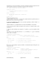
1
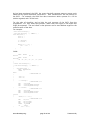
CMEN
=
CMEN | =
0
1 ;
CMEN | =
2 ;
;
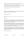
// Enable port 4.0 as PWM
(front)
// Enable port 4.1 as PWM
(rear)
}
/
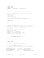
*****************************************************************************
*
This function initializes the Output Compare/Input Capture System on
Timer2/Port 1. Two captures are enabled: CC0 captures an event on Pin
CC1 will be triggered by a write to the low order Byte CCL1
*
*****************************************************************************/
/* The capcom unit when attached to timer2 is suitable for
frequency
*/
/* measurement and pulse generation
1.0,
*/
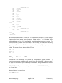
void capture_CC0_init(void)
{
T2CON
T2I1
T2I0
T2PS
=
=
=
=
0
;
0 ; /* Timer 2 = 12MHz/24 = 2us/count */
1;
1 ; /* /2 prescale for 2us/count */
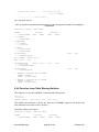
CTCON
=
0 ;
T2CM
T2R1
=
=
1 ;
0 ;
CCEN
CCEN
=
0 ;
|= 0x01 ;
CCEN
|= 0x0C ;
CCEN
|= 0x80 ;
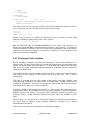
I3FR
= 0
P1 |
= 0x01
EX3
= 1
;
EX2
= 1
;
CC4EN
= 0x05
IP0
IP1
= 0
= 0
IP1
IP0
}
|= 0x26 ;
|= 0x3A ;
/* Timer 2 compare/capture in mode 1*/
/* No autoreload off CC0 */
/* Input capture on CC0 */
/* Timer 2 latched into CC1 on write
into CCL1 */
/* CC3 is output compare */
;
;
/* CC0 is initially -ve edge
triggered */
/* Put port 1.0 high for input
capture */
;
/* Enable capture interrupt for road
speed */
/* Enable output compare interrupt
for ign0 */
/* CC4 port 1.4 is output compare
mode 1
*/
;
;
/* Initialise interrupt priorities */
/* Make CC4 interrupt 3 priority */
/* Input capture is 2 priority */
/
******************************************************************************
*
Input Capture Interrupt On Port1.0/CC
******************************************************************************/
*
/* On every negative edge at P1.0, this routine is entered*/
/* Frequency calculation is possible using:
frequency
= 100000/(Timer2 Count Time * (this T2 - last
www.Phaedsys.org
page 136 of 194
Version 3.65)