1
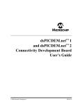
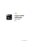
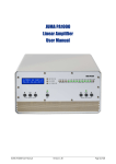
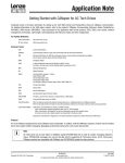
User Manual
22/10/2008
Version 1.0
© 2008, INGENIA-CAT S.L.
Contents
Introduction.................................................................................................. 4 What is a communication bridge and how does it work? .......................... 4 How to use it................................................................................................ 6 RS232/USB interface configuration .......................................................... 6 CAN interface configuration...................................................................... 6 Sending and receiving messages ............................................................. 8 Aspects of interest to the user .................................................................. 9 Application's execution flow....................................................................... 10 Command format....................................................................................... 12 Obtaining and modifying the CAN bus transmission speed .................... 12 Obtaining and modifying the mask, filter and mode................................ 12 Obtaining the program version and error report ..................................... 13 CAN message transmission ................................................................... 14 Receiving a CAN message..................................................................... 15 Communication error management ........................................................... 16 Syntax errors in the command line ......................................................... 16 RS232/USB-CAN transmission errors .................................................... 17 CAN – RS232/USB transmission errors ................................................. 18 Icons
Following is shown the meaning of the icons that reader can find on this manual.
Information
Provides the user with tips and tricks and other useful data.
Warning
Provides the user with important information. Omitting this warning may cause the
device not to work properly.
Critical Warning
Provides the user with critical information. Omitting this critical warning may
destroy the device.
1
Introduction
The CAN bus has become a real communications standard in the industry today due to its high
capacity, reduced wiring, great noise immunity, etc. This is why the need may arise in
developing new applications to connect several devices through the CAN interface. Yet if we
want to work with systems equipped with just RS232 or USB (a conventional PC, for example),
it is necessary to use an intermediate device called a communication bridge, which converts the
protocols.
RS232 Device
USB Device
RS232 bus
USB bus
Bridge CAN-RS232/USB
Bridge CAN-RS232/USB
CAN bus
CAN bus
CAN NETWORK
CAN bus
CAN Device
CAN bus
CAN Device
CAN bus
CAN Device
Figure 1: Typical application of a CAN-RS232/USB communication bridge
This manual describes the implementation of a firmware capable of establishing a bridge
between RS232/USB and CAN communications, using an iCM4011 communication module
from Ingenia. The function it performs is shown by the “Bridge CAN-RS232/USB” block that
appears in Figure 1.
What is a communication bridge and how does it
work?
A communication bridge allows communication between two or more devices using different
interfaces. The bridge is responsible for acting as an interpreter between the two, so that this
difference becomes transparent to them. A descriptive diagram is shown in Figure 2:
Figure 2: Example of communication between two devices with different interfaces
In our particular case, device 1 will be a PC, and interface A, its RS232 or USB port. Device 2
will be a CAN transceiver/receiver node (specifically, a PCAN-USB, from the PEAK-System
company).
Chapter 1: Introduction
4
The module iCM4011, programmed with RS232/USB to CAN bridge firmware, will act as a
communication bridge between both devices.
An application diagram is shown below:
Figure 3: Specific example of communication between two devices with different
interfaces
When the iCM4011 receives an ASCII format message through the RS232 or USB interface, it
converts it into CAN format and sends it through this bus. Similarly, when the iCM4011 receives
a message through the CAN bus, it converts it into ASCII format and sends it through the
RS232 or USB bus.
The main features of this communication bridge are outlined below:
• Sending and receiving CAN messages in ASCII format
• Compatible with CAN 2.0A and CAN 2.0B
• Communication speeds available:
o RS232/USB interface: set at 115200bps
o CAN interface: 10, 20, 50, 125, 250, 500 or 1000Kbps, which may be
configured using ASCII commands
• Configurable CAN communication parameters:
o Mask
o Filter
o Standard (11-bit identifier) or extended mode (29-bit identifier)
o Transmission speed
• Full report of communication errors.
Chapter 1: Introduction
5
2
How to use it
Microsoft ® HyperTerminal will be used as the PC application for exchanging messages through
the RS232/USB bus. The user may in the same way also be able to use PCAN-View software,
supplied by the manufacturer of the PCAN-USB device, to send and receive messages through
the CAN bus. Messages sent from HyperTerminal will therefore be displayed in PCAN-View.
Messages sent from PCAN-View will also be displayed in HyperTerminal.
RS232/USB interface configuration
In the first place, and according to the connection used between the iCM4011 and the PC, the
user must choose the serial USB or RS232 interface on the iCM4011 through its selection
jumpers (see the iCM4011 manual).
Remember that the USB interface on the iCM4011 is seen by the host as a serial
port.
Communication between the PC and the iCM4011 module takes place at a fixed speed, with the
following configuration parameters:
•
•
•
•
•
Transmission speed: 115200bps
Data bits: 8 bits
Parity: None
Stop bits: 1
Flow control: No flow control
CAN interface configuration
RS232/USB to CAN bridge firmware enables the configuration of CAN communications through
commands. As many as seven different transmission speeds can be chosen, ranging from
10Kbps to 1Mbps. There is also a mask and a programmable filter to decide the type of
messages we want to receive. Standard or extended modes can also be chosen by the user.
For further information about the CAN interface, consult the protocol specification
and processor product manual which you can find in the reference list.
Outlined below is an example of how to configure the transmission speed, the mask, the filter
and the mode (standard or extended). For further information about the commands, consult the
chapter Command format.
Chapter 2: How to use it
6
Figure 4: Baud rate, mask, filter and mode configuration
Other application options are the obtainment of the program version and a full error report. An
example is shown in the following figure:
Figure 5: Obtaining the program version and error report
Chapter 2: How to use it
7
Sending and receiving messages
In Figure 6 and Figure 7 the reader can see an example of sending CAN messages from
HyperTerminal and their subsequent monitoring in PCAN-View (RS232/USB – CAN
transmission) and vice versa. The information flow and direction between devices is also
described.
Figure 6: Information flow in RS232/USB – CAN transmission
Figure 7: Information flow in RS232/USB – CAN transmission
Chapter 2: How to use it
8
Aspects of interest to the user
With respect to HyperTerminal commands, it should be noted that the program does not
distinguish between capital and lower case letters and allows the use of the backspace key to
correct wrong command characters.
With respect to CAN bus connection, you should also remember to terminate the bus
appropriately. If you use Ingenia User Interface Board (UIB-PC104) with the iCM4011, a 120Ω
resistor can be inserted between CANH and CANL by simply enabling the third position of J2.
For further information about UIB-PC104, as well as module iCM4011, please
consult the documents in the reference list.
Chapter 2: How to use it
9
3
Application's execution flow
Outlined below is the application’s firmware execution flow:
1. Initial configurations
a. Input/output port configurations
b. CAN module configuration (baud rate, mask, filter and working mode)
c. CAN module reception interrupt configuration
d. UART configuration
e. UART reception interrupt configuration
2. Infinite loop
a. Process UART message
i. If received a full message, analyze the command received and place the
message in the UART FIFO process queue
ii. Process UART FIFO messages, if any.
b. Process CAN message
i. Process CAN module FIFO messages, if any.
UART and CAN interrupt routines perform the tasks of storing the character received (ISR
UART), as well as placing the message in the CAN FIFO process queue (ISR CAN). The flow
chart is outlined below:
MAIN LOOP
INITIAL
CONFIGURATIONS
INITIAL
CONFIGURATIONS
Configure
I/O pins
PROCESS UART
MESSAGE
Full Message
Received ?
Configure CAN
module parameters
PROCESS UART
MESSAGE
YES
Parse
message
Configure CAN
reception ISR
PROCESS CAN
MESSAGE
Configure UART
module parameters
NO
Put message into
UART FIFO
process queue
Configure
UART reception ISR
RETURN
UART messages
to process?
PROCESS CAN
MESSAGE
CAN messages
to process?
YES
NO
Process
messages from
CAN FIFO
ISR
CAN
ISR
UART
Parse
message
Save received
character
Put message into
CAN FIFO
process queue
RETURN
YES
NO
Process
messages from
UART FIFO
RETURN
RETURN
RETURN
Figure 8: Application's execution flow
Chapter 3: Application’s execution flow
10
The following resources are used by the iCM4011 device in this example:
•
•
•
•
•
•
CAN Module
UART Module
Timer Module
Interrupts:
o Interrupt due to CAN module reception
o Interrupt due to UART module reception
o Timer module interrupt
RAM memory (674 / 2048 bytes Æ 32.9 %)
Program memory (9242 / 16384 bytes Æ 56.4 %)
Chapter 3: Application’s execution flow
11
4
Command format
This chapter outlines the syntax of possible commands for configuring, sending and/or receiving
messages from the RS232/USB interface. The reader can also find details of application
features. Remember that you should always finish the command with a carrier return.
Obtaining and modifying the CAN bus transmission
speed
To modify the CAN bus transmission speed, the following command must be sent from the
serial communications program (i.e. HyperTerminal):
S <Space> BAUDRATE <Space> <Speed parameter>
The numerical value that accompanies the command indicates the speed we wish to use. To
choose a bus speed of 1Mbps, for example, we must type:
S BAUDRATE 0
Table 1 shows the equivalence between the command parameter and the transmission speed:
Parameter
0
1
2
3
4
5
6
Speed (Kbps)
1000
500
250
125
50
20
10
Table 1 : Transmission speeds
To obtain the transmission speed, the command to send is:
G <Space> BAUDRATE <Space>
The program will reply with a message similar to the one below:
BAUDRATE = 1 Mbps (0)
Obtaining and modifying the mask, filter and mode
To configure the mask, filter and working mode, the following syntax must be used:
S <Space> MASK <Space> <Identifier>
S <Space> FILTER <Space> <Identifier>
Chapter 4: Command format
12
S <Space> MESSAGE <Space> <Mode>
The MASK must be a numerical value expressed in decimal or hexadecimal format whose
range of values depends on the working mode chosen (standard or extended). If working in
standard mode, its value should be between 0 (0x0) and 211 bits-1 = 2047 (0x7FF). If working in
extended mode, however, the minimum value should be between 0 (0x0) and a maximum of 229
bits-1 = 536870911 (0x1FFFFFFF).
The FILTER should be a numerical value expressed in decimal or hexadecimal format. The
range of values covered follows the same rules as the MASK.
Finally, the possible MESSAGE values are 0 to select standard working mode, and 1 for
extended working mode.
To set the mask at 0xF, for example, the filter at 0xA and the mode as extended, the following
commands must be sent from the communications program, ending each one with a carrier
return:
S MASK 0xF
S FILTER 0xA
S MESSAGE 1
To obtain the mask, filter and mode value, the following commands have to be written:
G <Space> MASK
G <Space> FILTER
G <Space> MESSAGE
The program answers to each respective message will be:
MASK = 0XF
FILTER = 0XA
MESSAGE FILTER = EXTENDED
Another possibility is to set the working mode to 0. The reply will then be MESSAGE FILTER =
STANDARD.
Obtaining the program version and error report
To obtain the program version, the user must send the following command:
Chapter 4: Command format
13
G <Space> VERSION
The reply to this command will be a text such as:
VERSION = 1.00
To obtain the error report the user must send the following command:
G <Space> ERRORS
The response to this command will be:
ERROR MODE:
ERROR ACTIVE
RX ERROR COUNT:
0
TX ERROR COUNT:
0
In the example above, the application tells us there has been no communication error, due to
the transmission and reception counters being zero. ERROR ACTIVE is the normal operating
mode in which the CAN node can actively participate in communication.
If these counters exceed 127, the ERROR MODE would change to BUS PASSIVE. In this case,
the CAN node would have less priority for participating in communication.
If any counter exceeds 255, the system would also enter BUS–OFF. In this operation mode, the
node would be disconnected from the bus without being able to send or receive.
The RX ERROR COUNT and TX ERROR COUNT counters increase or decrease according to the
CAN bus specification.
CAN message transmission
For CAN message transmission, it is necessary to send a command using the following syntax:
T <Space> <S | X> <Space> <Identifier> <Space> < N | R > <Space> <DLC>
<Space> <Data>
Where:
•
•
•
•
•
•
<S> = Standard mode | <X> = Extended mode
<Identifier> = Identifier in hexadecimal (0x0000) or decimal (0) base
<N> = Normal message | <R> = Remote Transmit Request
<DLC> = Number of bytes to transmit
<Data> = Information in hexadecimal (0x0000) or decimal (0) base
<Space> = Space separating each field
To indicate that the message has been sent correctly the following message will appear on the
screen:
Chapter 4: Command format
14
Message transmitted successfully!
An error message will be displayed if there is a transmission failure. For further information see
the chapter referring to CAN–RS232/USB transmission errors.
An example of this kind of message might be:
T S 0x7FF N 2 0x3333
In this case, a message is sent in standard mode (indicated with the letter “S”) with the identifier
0x7FF. This is a normal type message (N) with two data bytes (2), which are 0x3333.
Another message with a Remote Transmit Request (RTR) might be:
T X 0x800 R
In this case, a message is sent in extended mode (indicated by the letter “X”) with the identifier
0x800. This is a remote transmission request (R) in which no data are indicated, as the aim is
for the device receiving this message to reply with the data needed by the requester.
Receiving a CAN message
If a CAN message is received, this will be automatically displayed on the screen in the following
format:
R <S | X> <Identifier> < N | R > <DLC> <Data>
The received message format is the same as the transmission format. An example of a
message received might be:
R S 0xA N 8 0x102030405060708
In this case, a message is received in standard mode (indicated with the letter “S”) with the
identifier 0xA. This is a normal type message (N) with eight data bytes (8), which are
0x102030405060708.
Chapter 4: Command format
15
5
Communication error management
Since this is a communication bridge, proper detection, warning and action against possible
communication errors is vital for the developed firmware to be fully operative and reliable.
To make it easier for the reader to understand, the errors have been divided into three types:
•
•
•
Syntax errors in the command line
RS232/USB-CAN transmission errors
CAN – RS232/USB transmission errors
Syntax errors in the command line
To avoid possible communication errors, the firmware rejects commands with badly expressed
syntax. Error messages related to poor input command syntax are shown in the following table.
Error code
Message
Possible causes
[E3]
Invalid command
Erroneous command. This is shown in the
case that the error does not come from any
of the sources described in this table.
[E4]
Invalid command
Identifier is not correct
In the transmission of a message, the
identifier field was expressed in
hexadecimal form (preceded by 0x) and
some of its characters were not between 0
and 9 or between A and F.
In the transmission of a message, the
identifier field was expressed as a decimal
and some of its characters were not
between 0 and 9.
[E5]
Invalid command
Data is not correct
In the transmission of a message, the data
field was expressed as a hexadecimal
number (preceded by 0x) and some of its
characters were not between 0 and 9 or
between A and F.
In the transmission of a message, the data
field was expressed as a decimal and some
of its characters were not between 0 and 9.
[E6]
Invalid command
Parameter is not correct
The mask or filter parameter was entered
incorrectly in configuration (as a
hexadecimal or decimal)
[E7]
Invalid command
Command is not correct.
Only T, G or S are
available
The command was started with characters
other than T (transmit message), G (get the
value of a specific parameter) or S (set the
value at a specific parameter).
[E8]
Invalid command
Identifier value is not
An S (standard identifier) was indicated in
transmitting the message, but an identifier
Chapter 5: Communication error management
16
standard. It is extended
greater than 11 bits was entered.
[E9]
Invalid command
DLC value is not correct
When the message was sent, a value
greater than 8 or another non-numerical
character was entered in the DLC field.
[E10]
Invalid command
Not enough parameters
In transmitting a message (T) or in
configuring a parameter (S), the respective
command lacks arguments.
[E11]
Invalid command
You must type a
command before Intro
The carriage return has been pressed
without having entered any character.
[E12]
Invalid command
You must type S or X
In transmitting a message, a character
other than S or X was entered in the
working mode field.
[E13]
Invalid command
You must type N or R
In transmitting a message, a character
other than N or R was entered in the
message type field.
[E14]
Invalid command
Baudrate range is
between 0 and 6
An out-of-range value has been chosen in
transmission speed configuration.
[E15]
Message is 0 for Standard
mode and it is 1 for
Extended mode
A number other than 0 or 1 has been
entered in the working mode configuration.
Identifier value is not
extended. It is standard
An extended X identifier has been indicated
in transmitting the message, but an
identifier of less than 12 bits has been
entered.
[E16]
Table 2: Possible typographical errors in the command line
RS232/USB-CAN transmission errors
The following table lists the possible errors that may occur when sending a message from the
RS232/USB interface, which will be shown in HyperTerminal.
Error code
Message
Possible causes
[E1]
Hardware UART FIFO
overflow. Message has
been lost!
The UART module hardware buffer has
been overrun. As a result, the message has
been lost.
[E2]
Software UART FIFO
overflow. Message has
been lost!
The software FIFO for messages from the
RS232 has been overrun. As a result, the
message has been lost.
[E19]
Message not transmitted.
Communication failed.
Check communication
The pending transmission wait time (five
seconds) has been exceeded.
Chapter 5: Communication error management
17
parameters before
retrying the transmission.
Reset all CAN devices to
recover normal operation
mode
The message could not be sent due to
incompatible communication configuration
parameters or due to a faulty device
connection.
Table 3 : Possible RS232/USB-CAN transmission errors
CAN – RS232/USB transmission errors
The following table lists the possible errors that may occur when sending a message from the
CAN interface, which will be shown in HyperTerminal.
Error code
Message
Possible causes
[E17]
Hardware CAN
reception buffer
overflow. Message has
been lost!
The CAN controller hardware buffer has
been overrun. As a result, the message has
been lost.
[E18]
Software CAN FIFO
overflow. Message has
been lost!
The software FIFO for messages from the
CAN bus has been overrun. As a result, the
message has been lost.
Table 4: Possible CAN – RS232/USB transmission errors
Chapter 5: Communication error management
18
Downloads
BridgeRS232CAN.zip
Downloads
19
References
Ingenia - “iCM4011 Product manual”
Ingenia - “UIB-PC104 Product manual”
Microchip - “dsPIC30F4011/4012 Data Sheet”. DS70135
Microchip - “dsPIC30F Family Reference Manual”. DS70046
Bosch - “CAN specification”
References
20