1
Important User
Information
Because of the variety of uses for the products described in this
publication, those responsible for the application and use of this
control equipment must satisfy themselves that all necessary steps
have been taken to assure that each application and use meets all
performance and safety requirements, including any applicable laws,
regulations, codes and standards.
The illustrations, charts, sample programs and layout examples
shown in this guide are intended solely for purposes of example.
Since there are many variables and requirements associated with any
particular installation, Allen-Bradley does not assume responsibility
or liability (to include intellectual property liability) for actual use
based upon the examples shown in this publication.
Allen-Bradley publication SGI- 1.1, Sufety Guidelines for the
Application, Installation, and Maintenance of Solid-State Control
(available from your local Allen-Bradley office), describes some
important differences between solid-state equipment and
electromechanical
devices that should be taken into consideration
when applying products such as those described in this publication.
Reproduction of the contents of this copyrighted publication, in
whole or in part, without written permission of Allen-Bradley
Company, Inc., is prohibited.
Throughout this manual we use notes to make you aware of safety
considerations:
A
!
ATTENTION:
Identifies information about practices
or circumstances that can lead to personal injury or
death, property damage or economic loss.
Attention statements help you to:
l
identify a hazard
l
avoid the hazard
l
recognize
Important:
the consequences
Identifies information that is
and understanding
for successful
the product.
Table
of Contents
Chapter
Page
Tit/e
. ___. . . . __. . _. . . . . . __. . __. _. . . ___. __.
1
Overview
2
Serial Cable Connections
__. __. . . . . . _ . _ _. . . . . _ . . . . .
RS-232 Connections
__ __. . _. . . . . _ __ . . _ . _ . . . . _ . . _ .
RS-422 Connections
Connection to Allen-Bradley
Programmable Controllers __ . . __ . __ . __. . __ ___.
4
5
2-l
2-2
...___..._._..._...._.___.___._.__._.._.
..__._.._......_....______...._.___._._.
___..__...____..._._....._....__..__._._
RS-422 Connection to 1771-DB Basic Module _ . . . . . .
RS-232 Connection to 1771-DB Basic Module . . . _ __ .
2-3
2-4
2-4
2-4
2-5
2-5
Connection to DL20 “MASTER” Displays
2-6
1771-DB
1775GA
1771-DA
3
l-l
_. . . . _ . __ .
DIP Switch Configuration
. . _ _. . _. . __ __ _. _ __ _. . . . . __ __.
DIP Switch Location
Baud Rate Selection . . . . . . _. _. _ . . . _ . . . . . . . _. . . . . .
Operating Mode Selection _. . . . . . _ . . __ ___. . . . . ___
SlaveMode
_..._.................___...._.......
. _ . . . . . . _ . . . ____ . . _ . __ . _ . . _ . . . . . _
Terminal Mode
3-l
3-l
Slave Mode Pfotoco/
4-1
. . . _. . . . . __. . _. . _. . . __. _.
Terminal Mode Commands
Terminal Mode Commands . . . . . . __. . . . . . . . . . _ . . . .
Terminal Mode Command Quick Reference _ . . _ ___.
Example of a 1771-DB Basic Module
PrintStatement
___........_........._..._....
3-2
3-2
3-3
5-l
5-4
5-5
Table of Contents
Chapter
6
Page
Title
Installation
Dimensions
. . . . _ . . . __ _. __ . _ . . . __
Installation Procedure . . _. _. . . . . . . .
Connection as Slave to DL20
“Master” Display . _ . . . . . . _ . . . . .
Selecting Baud Rate, Parity, and
Operating Mode . . _ . . _. . _ . . . . .
Specifications
6-l
6-l
.............
6-5
.............
6-5
. . . __. . . . . . ___. _. . . . . __. . __. . ___
Appendix A
ASCII Character Set
Appendix B
Dimensions
Appendix C
Fuse Replacement
lndex
.............
.............
Overview
DLlO Dataliner Message Displays are available in one-line,
two-line, and four-line versions, designed for panel
mounting in industrial environments. The units require a
110/120VAC power source.
In operation, the DLIO message display interfaces with a
host device, displaying alphanumeric messages in response
to serial ASCII data it receives from the host. The host
device can be a programmable controller, a computer, or a
master DL20 Dataliner message display. All programming
and storage of messages is performed at the host.
You can select either the Slave operating mode or the
Terminal operating mode for the DLlO. And you can use
either RS-232 (single device) or RS-422 (multi-drop) serial
communication with the host. RS-422 communication
allows you to use up to 100 DLlO displays on a single line up
to 4000 feet in length.
In the Slave mode, the DLlO receives data from a DL20
display, which acts as the “master”. The DL20 display can
in turn communicate with a host programmable controller
or computer. Each of the DLlO displays on the network can
be individually addressed. Note: Since the DL20 display
has only one serial port, you will not be able to connect a
printer to the DL20 in addition to the slave DLlO displays.
Whatever is sent out of the DL20’s RS-422 port is also sent
out the RS-232 port, and vice versa.
In the Terminal mode, the DLlO can receive data from a
computer or Allen-Bradley 1771-DB, 1775GA, or 1771-DA
modules (these modules interface to Allen-Bradley
programmable controllers) or other intelligent devices
capable of sending serial ASCII. In this mode, the DLlO
responds to ASCII control codes, similar to the way a CRT
terminal responds. In the terminal mode, displays are not
addressable; all DLlO displays on an RS-422 link will show
the same message.
This manual shows you how to make serial cable
connections to various host devices, and how to select the
baud rate, operating mode, and parity via dip switch
settings.
In addition, the manual explains the slave mode protocol
and terminal mode commands. Installation, power wiring,
and dimensional information is also included.
The RS-232 interface allows connection of only one DLlO
display, with a maximum recommended cable length of 50
feet.
RS-232 Connections
The RS-232 port of the DLlO display does not currently
support any hardware or software handshaking functions.
Only the RS-232 IN (Receive) terminal is used, along with
the respective “ground” terminal.
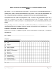
The following figure shows a typical connection between a
host device RS-232 port and the DLlO display. We
recommend that you use Belden 9463 shielded, twisted pair
cable, or equivalent.
The DLlO display is considered a “DTEY’ (Data Terminal
Equipment) device. The connection diagram assumes that
the RS-232 port of the host device is also a “DTE” type, as
most are. If instead it is a “DCE” (Data Communications
Equipment) type, then you should make your connection to
pin 3 of the host device instead of pin 2, as shown in the
diagram.
We recommend that you connect the shield at the
transmitting end only, as shown.
Note: If noise problems occur between a DL20 master
display and the slave DLlO display when RS-232
communication is used, we recommend that you connect the
shield of the communication cable to chassis ground at both
ends. However, the earth ground for each device must be
the same.
TYPICAL
HOST DEVICE
DLlO
(DTE)
RS-232
Equipment
Ground
1
Transmit
2
,
Receive
(not used)
SignalCommon
DISPLAY
TERMINALS
Pin Desiqnations
.
3
7
I
I
I
,---\
I
I
1
I
\
I
I
I
I
I
\J
Note: Some devices require that certain
hardware handshaking lines be asserted.
This may require a jumper from RTS to CT5
Refer to applicable product literature.
---------------,
RS-232 IN (Terminal
#2 on
one or two line display.
Terminal
#lO on a four line
display.)
-,
I
\
\
I
I
I
I
I
I
I
I
1
\
I
‘d’
RS-232 OUT (Not used, found
on four line display only.)
GROUND
(Terminal
#8 on a
one or two line display.
Terminal
#12 on a four line
/ display.)
Serial Cable
K-422
Connections
Connections
The RS-422 interface has these advantages
over the RS-232:
l
Improved noise immunity.
l
DLlO displays can be a distance of up to 4000 feet (314
mile) from the host device.
l
Up to 32 DLlO displays can be connected directly to the
RS-422 port of the host controller. Up to 100 DLlO
displays can be addressed when line drivers are used.
The RS-422 input port of the DLlO display does not
currently support any hardware or software handshaking
functions. Only the RS-422 IN (Receive) terminals are used.
The following figure shows a typical connection between a
host device RS-422 port and DLlO displays. We recommend
that you use Belden 9463 shielded, twisted pair cable, or
equivalent.
Note that pin or terminal numbers are not shown for the
host device. This is because the numbers vary for different
products. For actual pin numbers, refer to the appropriate
host device product literature. Terminal numbers for the
DLlO display are not shown either, since they are different
on one/two line and four line displays.
We recommend that you connect the shield at the
transmitting end only, as shown.
TYPICAL
Additional DLIO displays can
be multidropped as shown.
HOST DEVICE
Pin Desiqnations
RS-422
Equipment
Ground
Transmit
Transmit
Receive
Receive
DLlO
____---____-----------
Display
----------
(-)
(+ )
(-)
(+ )
Note: Some devices require that certain
hardware handshaking lines be asserted.
Refer to applicable product literature.
RS-422
OUT(
+)
Serial Cable Connections
Connection to
Allen-Bradley
Programmable
Controllers
2-3
Most Allen-Bradley Programmable Controllers provide a
variety of methods to interface RS-232 or RS-422 devices.
Almost all PLC-2 Family and PLC-3 Family Programmable
Controllers are apphcable. They include the following:
Mini PLC-2
Mini PLC-2/E,
-2/05, etc.
PLC 2/20 (1772-LPl,
LP2)
PLC 2/30 (1772-LP3)
PLC 3
PLC 3/10
PLC 5
The most common means of providing serial interfaces for
the above Programmable Controllers include the following
optional modules:
1771-DB Basic Module (All Programmable
listed above)
1775-GA Peripheral
Family only)
Communications
Controllers
Module (PLC-3
1771-DA ASCII I/O Module (All Programmable
listed above)
Controllers
Serial Cable Connections
2-4
1771-DB
The Allen-Bradley 1771-DB Basic Module provides a costeffective and efficient serial interface to almost all AllenBradley programmable controllers. It can be plugged into
any slot of a standard 1771 local or remote I/O rack. This
includes Mini PLC applications. The module can store all
messages in battery-backed RAM or EPROM. It can be
programmed to transmit these messages along with status
or variable data from the programmable controller. The
1771-DB Module has access to the programmable
controller’s program and memory.
The 1771-DB Module supports both RS-232 and RS-422
(multidrop) applications. If RS-422 is used, up to 32 DLlO
Displays can be directly connected and uniquely addressed.
Up to 100 DLlO displays can be uniquely addressed if RS422 repeaters are used.
For more information on the 1771-DB Basic Module, refer to
its user’s manual. Connection of DLlO displays to the 1771DB peripheral port and a program statement example are
described later.
1775-GA
The 1775GA Peripheral Communications Module is only
applicable to Allen-Bradley PLC-3 Family Programmable
Controllers. It is a more powerful module and plugs directly
into the PLC-3 chassis. It has several serial ports and is
capable of performing many unique tasks at one time for a
PLC-3 System. The 1775-GA currently supports only RS232 serial port specifications. However, an RS-422 network
with many DLlO displays can easily be implemented by
using an RS-232 to RS-422 Converter. Refer to 1775-GA
literature for more information.
1771-DA
The 1771-DA ASCII I/O Module provides a serial interface
for almost all Allen-Bradley programmable controllers. It
can be plugged into any slot of a standard 1771 local or
remote I/O rack.
The 1771-DA has no memory or programming language.
All DLlO display messages would be stored in the
programmable controller’s memory. Having messages
stored in PC memory, along with the application program,
could be considered an advantage; however, in many cases
ASCII message storage is too great a burden for the limited
memory capacity of programmable controllers. Also, the
programming requirements may be considered “less
friendly” by unfamiliar users.
Serial
Cable Connections
2-5
RS-422 Connection to
1771~D5 Basic Module
1771-DB
PeripheT
Chassis/
Shield
1
RS422TXD’
25
RS-422
TXD
,J
RS-422
RXD
,6
RXD’
,g
RS-422
DL10
Port
i-----
1 T’----,J’
\,
I
I
\
,A\
;
I
I
\,’
,I
1,
I-
\
Additional DLlO displays
can be multidropped as
shown.
Display
I
r----------+
----------------~
RS-422
RS-422IN
,i;-----,A,
IN (-)
\
I
I
I
(+)
I
’
x-0
RS-422 OUT ( + )
not used
4-
6
20
tP
RS-232 Connection to
1771~DB Basic Module
1771-DB
RS-232
Peripheral
Port
Chassis I Shield
1
TXD - OUTPUT
2
RXD -INPUT
SIGNALGROUND
3
,
DLlO DISPLAY
/
r
I
5620
-
/
\
\
I
I
I
I
I
I
I
I
I
\
4
~~-------~-_________
I
I
I
I
I
\
‘-’
4-
\
\
\
RS-232
I
I
I
I
I
I
\
I
‘-’
-
IN (-)
RS-422
IN ( +)
I-
RS-422 OUT (-)
not used
-
R5-422
I
I
\
\M’
\,’
\
I
I
I
\
I
IN
RS-232 OUT
(not used)
RS-232
Ground
Serial Cable Connections
2-6
COnnection
t0
OL20 “MASTER”
f%p/ayS
As previously described, up to 32 DLlO displays (slave
mode) can be connected to the RS-422 port of a DL20 display
(Master). If RS-422 line drivers are used, up to 100 DLlO
displays could be connected to, and uniquely addressed by,
the DL20 display (Master). The DL20 Display (Master) can
then connect to a host programmable controller or Computer
via either its RS-232 port or its parallel input port.
When this type of configuration is used, all messages are
stored in the Master DL20 display. All the host controller is
required to do is trigger a particular message stored in the
Master DL20 display. When particular messages are
created, they can be assigned an attribute which designates
that messages to be displayed on any particular slave DLlO
display, all slave DLlO displays, or just the DL20 display.
Note: Since the DL20 display has only one serial port, you
will not be able to connect a printer to the DL20 in addition
to the slave DLlO displays. Whatever is sent out of the
DL20’s RS-422 port is also sent out the RS-232 port, and vice
versa.
For more information on DL20 displays (Master) refer to
DL20 display User’s Manual Publication 2706-801.
Addresses can be assigned to Slave DLlO displays by setting
DIP Switches as described in Chapter 3 of this manual. The
“slave mode” must be selected for this configuration.
The following diagram illustrates this configuration:
7
)
Serial
RS-232 or
Parallel I/O
interface
DL20
Display
(Master)
A
RS-422 (Out)
b
A
RS-422
RS-422
RS-422
(IN)
WI
(IN)
Note: If noise problems occur between a DL20 master display
and one slave DLlO display when RS-232 communication is used,
we recommend that you connect the shield of the
communication cable to chassis ground at both ends. The earth
ground for each device must be the same. Thiswill help to
improve noise immunity.
DIP Switch Location
The DLlO displays are configured via a lo-position DIP
switch located under the top cover of a one or two line
display, or on the right side of a four line DLlO.
CIRCUIT
UP(OPEN)
BOARD
DOWN
Each individual switch has a number associated with it, as
shown above. A switch is OPEN when it is UP with respect
to the circuit board. If any changes in DIP switch settings
are made while power is on, then AC power to the DLlOdisplay must be recycled before the new switch selections
are recognized.
On power-up, the DLlO will display prompts which indicate
which mode and baud rate have been selected.
EXAMPLE:
Baud Rate
Selection
TESTING UNIT 1.0 4L
SLAVE MODE
BAUD BATE = 300
I
I
BAUD RATE SWITCHES
Baud Rate
300
1200
9600
9600
I
Switch #9
UP
UP
DOWN
DOWN
I
Switch #lO
UP
DOWN
UP
DOWN
The baud rate must be selected to match the baud rate of the
host device. Generally, any of the above selections can be
used, however it is possible that some host devices could be
programmed to transmit too many characters too fast at the
9600 baud rate. If a problem is encountered, the baud rate
can be lowered. The DLlO will display the selected baud
rate as one of its initial power up prompts.
DIP Switch Configuration
Operating Mode
Selection
~
Depending on which mode is selected via Switch #8, the
remaining switches (1 - 7) will have different meanings. If,
for example, “Slave Mode” is selected, Switches 1 - 7 will
define the DLlO display’s address. If “Terminal Mode” was
selected, Switches 1 - 7 would have other meanings. These
switches are defined separately for each mode.
Slave
Mode
If the “slave mode” has been selected (Switch #8 down), then
switches 1 through 7 define an address for that DLlO
display. The values for each switch are illustrated below.
The address of the DLlO is the sum of the values for all of
the switches (1 - 7) that are up.
Address
Switch #
Value
1
2
3
4
5
6
7
64
32
16
8
4
2
1
Addressing Example
‘Switch #
Switch Position
1
2
3
4
5
6
7
Dn
Up
Dn
Up
Up
Dn
Dn
The above Address = 44.
The SLAVE MODE is generally selected for applications
requiring more than one DLlO Display to be connected and
uniquely addressed on an RS-422 network (although a
single DLlO Display and RS-232 interface could be used). It
allows displays on the link to each display different
messages.
The SLAVE MODE must also be selected when multiple
DLlO Displays are connected to a Master DL20 Display.
The SLAVE MODE protocol is different from the terminal
mode protocol. They are defined separately in Chapters 4
and 5 respectively.
D/P Switch Configuration
Slave Mode
(continued)
3-3
Certain slave addresses are not valid for DLlO displays
when connected as slaves to a DL20 master. These illegal
decimal addresses are: 0,4,6,7,13,18,20,22,43,45,48-57.
It should be noted that address 127 performs a special
function explained in the Slave Mode Protocol in Chapter 4.
When multiple DLlO displays are placed on one RS-422
link, more than one DLlO can have the same address.
DLlO’s with the same address will all respond to commands
addressed to them.
Termha/ Mode
If the terminal mode is selected (Switch #8 up>, then
switches 1 through 7 have the following meanings.
Switch #
UP
DOWN
1
2
Definition
Status
I
DOWN
Enable Cursor
Disable Cursor
I Not Used
UP
DOWN
Enable Auto New Line
Disable Auto New Line
DOWN
Not Used
UP
DOWN
Odd Parity
Even Parity
UP
DOWN
Enable Parity
Disable Parity (None)
DOWN
Must be down for terminal
I
mode
Note: When parity is selected send 7 data bits plus parity
bit and 1 stop bit. When no parity is selected send 7 or 8
data bits and 1 stop bit.
The terminal mode is generally selected for applications
that do not require more than one DLlO display to be
uniquely addressed by a host controller. In this mode, DLlO
displays can be connected to a host controller’s RS-232 or
RS-422 interface. As previously described, several DLlO
displays could be multidropped on an RS-422 network,
however in terminal mode unique addresses cannot be
assigned. Therefore, transmitted messages would be
displayed on all DLlO displays connected to the RS-422
network.
DIP Switch Configuration
3-4
~ermind Mode
(continued)
In terminal mode, the DLlO display acts on simple control
codes and escape sequences similar to a “dumb” CRT
terminal. This terminal mode protocol is different from the
slave mode protocol. The slave and terminal mode protocols
are defined separately in Chapters 4 and 5 respectively.
S/we Mode Protoco/
The protocol described here is applicable when the slave
mode has been selected as described in Chapter 3.
Applicable ASCII characters are listed in Appendix A.
How to display text on a DLlO display:
items shown in this packet:
Send the four
20 Characters
for Display
1. Send out the twenty characters you want to be displayed.
Any valid ASCII character, upper or lower case, can be
sent. Control codes do not apply.
2. Send out the slave address (byte). This is a one-byte
character, ranging from 1 thru 127 decimal equivalent
thru 7F hex).
(1
Invalid decimal slave addresses: You cannot use
decimal addresses 0,4,6,7,13,18,20,22,43,45,48-57.
3. Send out the line number (byte). Currently, valid line
numbers are line 1 thru line 4. This byte should be 1
thru 4 (decimal equivalent), not ASCII 1 thru ASCII 4.
The ASCII characters for lines 1 thru 4 are: Control A,
Control B, Control C, and Control D.
4. Finally, send a carriage return (ASCII Control M,
Dee 13, Hex OD).
An example of a typical print statement for a Catalog No.
1771-DB basic module with a DLlO connected to its
peripheral port would be
Slave
1
J
100 PRINT
#“VALVE
NUMBER
1 OPEN”,
J
CHR (1). CHR(l),
f’
CTRL A
t
CTRL A
Carriage
Line 1
Return
J
CHR (13)
t
CTRL M
The message “VALVE NUMBER 1 OPEN” on line one of
slave number one would be displayed. Note that to send the
address, line number, and carriage return required that you
use the print CHR (decimal character equivalent) function.
S/a we Mode Protocol
4-2
%Ve
MO&
Wild card feature: A DLlO display addressed as 127 will
understand any data transmitted to it, regardless of what
address is assigned in the packet. Also, any packet
containing the address 127 will be received by all DLlO
displays, regardless of their addresses. This allows you to
efficiently route a message to all displays. Multiple DLlO
displays on an RS-422 link can have the same address and
will respond to messages sent to that address.
bOtOCO/
(continued)
Control code F: This is a flash code. Send this code if you
wish to have characters flashing in your display. Every
character received after you send control F will flash. To
cancel the flash mode, send a second control F.
Control code R: This is a reset command. When the DLlO
display receives a control R, all data registers in the DLlO
are reset, clearing transmitted data. For example, if you
send 10 characters, then control R, the 10 characters will be
cleared and you can then start over by sending 20 characters
followed by the slave address, line number, and carriage
return.
Control R also resets the flash status to non-flash.
We recommend that you send a control R to all DLlO
displays when the host controller is powered up. This clears
any erroneous data which may be inadvertently transmitted
when the serial port powers up.
To clear one or all lines of a DLlO display:
following packet:
Send the
The table below indicates what line number byte you must
send to clear line 1,2,3,4,
or all lines.
Line Number Byte
/
Action
Dee
Clear Line 1
Clear Line 2
Clear Line 3
Clear Line 4
Clear all Lines
1
2
3
4
50
ASCII
Control
Control
Control
Control
2
Hex
A
B
C
D
1
2
3
4
32
Terminal Mode
Termha/ Mode
C0ll7maf?&
Commands in this section are applicable only when the
“Terminal Mode” of operation has been switch-selected as
described in Chapter 3.
This chapter defines each command. These definitions are
followed by a “Command Quick Reference” on Page 5-4.
Applicable ASCII characters are listed in the ASCII
conversion table in Appendix A. Note: A denotes a
CONTROL prefix, ESC denotes an ESCAPE code.
The commands in this section can be sent serially to DLlO
Displays along with the message characters to implement
the various display functions.
Cursor Up (AK)
Positions the cursor directly above the current position
unless on the top line, then the cursor is moved to the bottom
line.
Cursor Down (rW)
Positions the cursor directly below the current position
unless on the bottom line, then the cursor is moved to the top
line.
Cursor Left (AH)
Moves the cursor one position to the left. If cursor is at the
beginning of the line, the cursor is moved to the last position
on the above line. If on top line, the cursor is brought to the
last position on the bottom line.
Cursor Right (AL)
Moves the cursor one space to the right. If cursor is at the
end of the line, the cursor is moved to the beginning of the
next line. If it is at, the last line, the cursor is brought to the
top line.
Cursor Return (AM)
Moves the cursor to the beginning
of the current line.
Line Feed (N)
Moves the cursor down one line. If the cursor is at the last
line, the cursor stays put and the above lines are moved up
one line.
Reverse Line Feed (ESC J)
Same as the line feed, but in the opposite direction.
Cursor Home (AT)
The cursor is moved to the first position on the display.
Terminal Mode Commands
5-2
Clear Screen (ESC*)
The cursor is moved to the first position and the display is
cleared.
Teffl’?hd
MO&
cOlW77~f7dS
(continued)
New Line (Al)
Performs both carriage return and line feed. Cursor
remains on the same line.
Delete Line (ESC R)
Clears the line the cursor is on and the cursor remains
where it is.
Insert Line (ESC E)
The line the cursor is on and all lines below it are moved
down one. The last line is deleted from the display. The line
the cursor is on is cleared. The cursor remains in the same
position on the display.
Set Cursor Position (ESC = Row Column)
The cursor will move to the row and column defined by this
character sequence. “Row” and “column” are each one
character as defined by the following table. Notice that the
respective characters required to designate “row” and
“column” are not the Decimal, Hex, nor ASCII equivalent of
the actual row and column position. If a parameter exceeds
those noted below, the cursor will default to the greatest row
and/or column.
Column
12345678
Row
1
2
3
4
ASCII
Equivalent
SP
!
*
#$%&‘()*+,
Decimal
Equivalent
32
33
34
35
36
37
38
39
40
41
42
43
44
45
46
Hex
Equivalent
20
21
22
23
24
25
26
27
28
29
2A
2B
2C
2D
2E
9
10
11
12
13
14
-
Example:
15
16
17
18
19
20
47
48
49
50
51
2F
30
31
32
33
./0123
The following ASCII character sequence will
place the cursor in Row 3, Column 9 of a four line
display:
ESC = “(
Cursor Attribute Set
ESC . 0 Set cursor invisible.
ESC . 1 Set cursor visible.
Terminal Mode
Terminal Mode
Commands
(continued)
Commands
Character Attribute Set
ESC G 0 Normal Mode Set
ESC G2 Flash Mode Set
Every character received after “flash mode set” will flash
until a “normal mode set” command is received.
Monitor Mode (Esc U)
Monitor Mode will force the DLlO to display all control codes
it receives as HEX numerical code. While in this mode, the
display will ignore the command associated with the control
code.
ESC u or ESC X
Cancels monitor mode.
Display Status (ESC H)
The unit will temporarily display for approximately three
seconds the current status of the display in the following
format:
Terminal Mode - Baud Rate
Terminal Mode Commands
Terminal Mode
Command Quick
Reference
ASCII
CHARACTERS(S)
DECIMAL
EQUIVALENT
DECIMAL
EQUIVALENT
Cursor Up
AK
11
OB
Cursor Down
AV
22
16
Cursor Left
AH
08
08
Cursor Right
AL
12
oc
AM
13
OD
AJ
10
OA
COMMAND
Carriage
Return
Line Feed
Reverse Line
Feed
ESC J
Cursor Home
AT
Clear Screen
ESC*
New Line
27
106
1B 6A
20
27
14
42
1B 2A
31
A /
1F
Delete Line
ESC R
27
82
1B 52
insert Line
ESC E
27
69
1B 45
27
61
1B 3D
Set Cursor Pos.
ESC =
(line)(column)
Set Cursor
Invisible
ESC.0
27
46
48
1B
2E
30
Set Cursor
Visible
ESC 1
27
46
49
1B
2E
31
Set Normal
Mode
ESC G 0
27
71
48
1B 47
30
Set Flash Mode
ESC G 2
27
71
50
1B
32
Monitor Mode
Enable
ESC U
27
85
1B 55
ESC u or
ESC X
27
27
117
83
1B 75
1B 58
ESC h
27
104
1B 68
Monitor
Disable
DISPLAY
STATUS
Mode
47
Note: * denotes a CONTROL prefix, ESC denotes an ESCAPE code.
Terminal Mode
Example of a 1771-D/3
Basic Module Print
Statement
Commands
The following statement would display a message on line
one of a DLlO display in the terminal mode connected to the
1771-DB module peripheral port.
PRINT #CHR (20)
(moves cursor to the first character position on the DLlO)
PRINT #VALVE NUMBER 1 CSD,
Note: If the comma at the end of the print statement is not
included, the 1771-DB module will automatically send out a
carriage return. This will move the cursor of the DLlO to
the first position of the same line. With the comma, the
cursor will stay at its finish position. This is useful when
updating variable information in a message, or stringing
two consecutive print statements.
Installation
Dimensions
Refer to Appendix B for panel cutout dimensions, overall
dimensions, optional flush mount dimensions, and enclosure
dimensions.
Procedure
The procedures below will guide you in mounting and
wiring the DLlO display in a custom panel or enclosure, or
in a Bulletin 2706 enclosure, Catalog Number 2706-NE1 or
2706-NE2.
To install the display in a Bulletin 2706 enclosure: The
Series A enclosures have threaded nuts welded inside the
six display mounting holes and are intended for use with
Series A and B DL20 displays or Series A DLlO displays
only.
Series B enclosures will work with all series letter DLlO and
DL20 displays. They do not have threaded holes. If a Series
B enclosure is not available, it is possible to use a Series A
enclosure by drilling out the six threaded mounting holes
with a 3/16” drill.
When a DLlO display is installed properly, the display
faceplate will provide NEMO Type 12, Type 13, and Type 4
(indoor use only) enclosure integrity. Earlier Series A
displays will provide NEMA Type 12 and Type 13 enclosure
integrity only.
To install the display in a panel or custom enclosure:
1. Cut out a rectangular opening and drill six holes
according to panel cutout dimensions in Appendix
At
0
B.
CAUTION: Do not install the display in the
panel or enclosure until all cutouts and holes are
completed. Metal filings accumulated when
cutting and drilling could enter ventilation holes
on the display and cause the display to fail.
2. Insert the display in the panel or enclosure cutout.
Screw the six mounting nuts (supplied) onto the
mounting studs and tighten.
Note: Series A devices are not equipped with mounting
studs. Use # 10 mounting screws.
6-2
Installation
Procedure
To wire power and communication
lines:
(con tin ued)
1. Series B and later displays: Connect a 1 lo/120 VAC
Z!Ilo%, 47/63 Hz voltage source to terminals H, N, G of
the DLlO display. Terminals are explained on Pages 6-3
and 6-4.
Series A displays: Connect a 120 VAC k lo%, 50160 Hz
voltage source to terminals H, N, G of the DLlO display.
The 120 VAC supply line to the display must have 15
Amp branch short circuit protection maximum (this is
not required for Series B and later displays).
7
A0
WARNING: Terminal 3 (the G terminal) must
be connected to a reliable low impedance earth
ground to protect the display from electrical
noise. This ground connection will also protect
personnel from electrical shock if the electronics
short to the DLlO case.
Do not turn on power to the display until all wiring to the
serial port is completed.
2. Connect communication lines from the host
programmable controller, computer or DL20 master to
the serial port of the DLlO. Belden 9463 shielded twisted
pair is recommended. Refer to Chapter 2 of this manual
for details on serial port connection.
?
A
0
WARNING: The DLlO has simplex (single
direction) communication only. The DLlO should
only be used for non-critical display applications.
Simplex communication provides no ACWNAK
(duplex) verification that messages sent by the
programmable controller or computer have been
received and displayed by the DLlO.
6-3
installation Procedure
(continued)
The serial data format for the RS-232 and RS-422 ports is
identical. It is very important that the format for the
DLlO and the connected device be set the same.
Baud rate: 300,1200, or 9600
Data length: 8 bits (including parity if any).
Parity: odd, even, or none.
Stop bits: 1
G
IN
N
D
RS
RS-232
OUT
I
DN
-+
-+T
0
G
U
N
D
u
H
N
G
One and Two Line DLIO Terminal Identification
TERMINAL
DEFINITION
1
RS-232 Port Common
(Internally connected to equipment
ground)
RS-232 IN - Receive Data
RS-422 IN ( - ) - Receive Data
RS-422 IN ( + ) - Receive Data
Not Used
Not Used
Not Used
Serial Port Common
(Internally connected to equipment
ground)
1
2
3
110/120 VAC Hot
110/120 VAC Neutral
Equipment Ground
6-4
Installation
Procedure
(con timed)
RS-232
l2OVAC
w
I
HN
1
-
G
2
3
4
5
0
G
u
N
OUT
IN
+
-+
6
7
NT
a
9
IO
D
11
12
Four Line DLIO Terminal Identification
TERMINAL
1
2
3
4
i
7
8
9
10
11
12
DEFINITION
110/120 VAC Hot
110/120 VAC Neutral
Equipment Ground
Not Used
RS-422 IN ( - ) - Receive Data
RS-422 IN (+ ) - Receive Data
Not Used
Not Used
Not Used
RS-232 IN - Receive Data
Not Used
Serial Port Common
(Internally connected to equipment
ground)
The DLlO uses low voltage signaling on the serial input.
Any low voltage signals in a control panel are particularly
noise susceptible. Although the DLlO contains circuitry to
filter noise, reasonable precautions are necessary to ensure
proper operation of the DLlO. The 120 VAC ground
terminal (3) of the DLlO must be tied to a good earth ground.
Data input lines should be routed away from high energy
wiring, transformers, solenoids or coils, and devices known
to generate large amounts of EMI or RFI. The
communications cable should not be installed in the same
conduit or in close proximity with AC or high level DC I/O
lines. It can be installed in the same conduit with low level
DC I/O lines (less than 10 Volts) and low power signals. A
shielded cable should be used, and the shield should be
connected to ground at the transmitting device end only.
6-5
Installation
Transient noise suppressors across solenoids and coils are
often helpful in reducing interference. Noise is a very
insidious thing. A device may work for months and then fail
due to noise. After the power is cycled OFF then ON, the
failure may disappear, and attempts to duplicate it will
prove frustrating.
Procedure
(continued)
DLlO slave displays can be connected to the DL20 display
serial RS-232, or RS-422 port. Up to 32 DLlO slaves can be
connected to the RS-422 output port of the DL20 display at a
maximum distance of 4,000 feet without the use of in -line
amplification. Using in-line RS-422 amplification up to 100
separately addressable slave DLlOs can be connected to the
RS-422 output of the DL20 out to a maximum distance of
4,000 feet.
Connection as Slave
to DL20 “Master”
Display
Connect the slaves to the RS-422 output of the DL20 using a
100% shielded twisted pair cable with drain wire. We
recommend Belden 9463, or equivalent cable.
Slave addresses and baud rates are selected by a DIP switch
on the DLlO (see Chapter 3). The DLlO baud rate must
match that of the DL20’s serial port.
Note: When changing the baud rates of either the DLlO or
DL20, power must be recycled before the new baud rate
takes effect.
DLlO
DL20 Master
-PLC
us-422
RS-422
out -
4
I
c
I
/-\
\I\
1
RS-422
/-\
I
I
DLlO Slave
Slave
IN I
I
I
/-\
\
1
I
I
I
I
/-\
\
RS-422
IN -
I
I
JRS-422
IN +
+
Connection
to Host.
4
4,000 Feet Maximum.
.
Note that it is also possible to use the RS-232 output of the
DL20 to connect to one DLlO slave, however the distance
limitation is 50 feet.
Selecting Baud Rate,
Parity, and Operating
Mode
Refer to Chapter 3 for DIP switch settings.
Specifications
General
Character Height
One Line Display: 0.59” (15.1 mm)
Two Line Display: 0.44” (11.3 mm)
Four Line Display: 0.49” (12.5 mm)
I
ICharacters
per line:
I
Electrical
Display Type:
Blue-green vacuum fluorescent,
5x7 dot matrix
Serial Input:
RS-232 and RS-422
Baud Rate (selectable):
300, 1200, or 9600
Parity (selectable):
Odd, even, none
Data length:
7 data bits, + parity, 1 stop bit
nput Power
One & Two Line Displays
Four Line Displays
Fuse Type
One & Two Line Displays
Environmental
20
Series B & later: 110/l ZOVAC
f lo%, 50/60 Hz, 1OVA max
Series A: 12OVAC k lo%, 60H2,
1OVA max
Series B & later: 1 1O/l 20 VAC
t lOoh, 50/60 Hz, 55VA max
jeries A: 12OVAC + lo%, 60 Hz,
55VA max
0.25A, Type MDL, 250VAC
Four Line Displays, Series B
& later
Aux. power supply board fuse FU 1:
0.375A, Type MDL, 250VAC
Incoming power fuse: 1.5A, Type
MDL, 125VAC
Four Line Displays, Series A:
0.375A, Type MDL, 250VAC
Operating Temperature:
Humidity Rating:
5% to 95% (without
condensation)
NEMA Rating, Series B & later
NEMA Type 12/l 3 and 4 (indoor use
only) panel mount
NEMA Rating, Series A
NEMA Type 12/13 panel mount
7-2
Specifications
(continued)
Approximate
Dimensions
,
One and Two Line Displays
Four Line Displays
Series
Series B
& Later
Front Panel
Depth
Front Panel
Depth
4.4” (1llmm)H
14.4” (365mm) W
3.25”
(83mm)
6.2” (157mm) H
14.4” (365mm) W
5.1 ‘I
(130mm)
-Dee
0
1
2
3
4
5
6
7
8
9
10
11
12
13
14
15
16
17
18
19
20
21
22
23
24
25
26
27
28
29
30
31
Control
Q&
&t
000
001
002
003
004
005
006
007
010
011
012
013
014
015
016
017
020
021
022
023
024
025
026
027
030
031
032
033
034
035
036
037
00
01
02
03
04
05
06
07
08
09
DA
OB
oc
OD
OE
OF
10
11
12
13
14
15
16
17
18
19
1A
1B
1c
1D
1E
1F
NlJL
SOH
STX
ETX
EOT
ENQ
ACK
BEL
BS
HT
LF
VT
FF
CR
SO
51
DLE
DC1
DC2
DC3
DC4
NAK
SYN
ETB
CAN
EM
SUB
ESC
FS
GS
RS
us
Decec&Char
CTRL
CTRL
CTRL
CTRL
CTRL
CTRL
CTRL
CTRL
CTRL
CTRL
CTRL
CTRL
CTRL
CTRL
CTRL
CTRL
CTRL
CTRL
CTRL
CTRL
CTRL
0
A
B
C
D
E
F
G
H
I
J
K
L
M
N
0
P
Q
R
5
T
CTRL
CTRL
CTRL
CTRL
CTRL
CTRL
U
V
W
X
Y
2
Escape
CTRL ,
CTRL D
CTRL .
CTRL I
32
33
34
35
36
37
38
39
40
41
42
43
040
041
042
043
044
045
046
047
050
051
052
053
20
21
22
23
24
25
26
27
28
29
2A
2B
SP
!
#
5
%
&
’
(
)
44
45
46
47
48
49
50
51
52
53
54
55
56
57
58
59
60
61
62
63
054
055
056
057
060
061
062
063
064
065
066
067
070
071
072
073
074
075
076
077
2c
2D
2E
2F
30
31
32
33
34
35
36
37
38
39
3A
38
3C
3D
3E
3F
,
.
I
0
1
2
3
4
5
6
7
8
9
:
;
<
=
>
7
l
+
64
65
66
67
68
69
70
71
72
73
74
75
76
77
78
79
80
81
82
83
84
100
101
102
103
104
105
106
107
110
111
112
113
114
115
116
117
120
121
122
123
124
40
41
42
43
44
45
46
47
48
49
4A
48
4C
4D
4E
4F
50
51
52
53
54
@
A
B
C
D
E
F
G
H
I
J
K
L
M
N
0
P
Q
R
S
T
85
86
87
125
126
127
55
56
57
U
V
W
88
89
90
91
92
93
94
95
130
131
132
133
134
135
136
137
58
59
SA
58
SC
SD
SE
SF
X
Y
Z
[
\
1
A
_
96
97
98
99
100
101
102
103
104
105
106
107
108
109
110
111
112
113
114
115
116
117
118
119
120
121
122
123
124
125
126
127
140
141
142
143
144
145
146
147
150
151
152
153
154
155
156
157
160
161
162
163
164
165
166
167
170
171
172
173
174
175
176
177
60
61
62
63
64
65
66
67
68
69
6A
68
6C
6D
6E
6F
70
71
72
73
74
75
76
77
78
79
7A
78
7C
7D
7E
7F
\
a
b
c
d
e
f
z
i
j
k
I
m
n
0
p
q
r
s
t
u
v
w
x
y
z
{
1
)
DEL
General
This Appendix wiI1 illustrate the dimensions for the DLlO
one, two and four line displays. Dimensions are shown in
inches. (Dimensions in parentheses are in millimeters.) All
dimensions are approximate and are not intended for
manufacturing purposes.
Panel Cutout
Dimensions
0-.-718
.-
13.87
(352.3 mm)
(5.5 mm)
-
CIA
t’OLE
(6 PLACES)
-a.-.-
.-__,_._.
-.-.-.-.-.-.Q-.-.-.-.-.-
.-.-.
- .-.-._.
i
8
i
I
3.50
(89 mm)
cutout I
b
I
I
i (Ss3.h87m5m)
1:
I
I
.-.-.-.-.-__.-._.-.-.-.-
Cl.0
13.75(349.3
htl14
(1.5 mm)
il -
.-.-.-.-.-.-.-.-.-.-.-.-.
mm)
cut out
One and Two
DLlO
Line
Displays
13.87
(352.3 mm)
,3.62~~~~~
mm)
0.218
p
._.-.___.-.-._.-.-.-.-.~.
i
i
i
i
i
i
i
i
i
I
i
t
5.26
(133.6 mm%
cut out i
i
i
.:q.-
-
.-.-___
-.-.-
.-.-.
- .-.-.;
t
ii
;
5.68
J144.3 mm)
i
i
.-.-.-.-.
-.-.-.-
.-.-.-.-.
j+
I
Four Line
DLIO
Display
Overall Dimensions
DIM B
TYPE DISPLAY
DIM A
ONE LINE DISPLAY
1.250”
(31 .Emm)
10.125”
TWO LINE DISPLAY
1.700”
(43.2
8.812”
mm)
(257.2mm)
(223
8mm)
One and two line DLlO dimensions.
Series B and later.
(345.4
mm)
I_(
2.58
65.5 mm)
Top View
DIM. “A”
SEE CHART
Side View
14.37
(365.0 mm)
4
I*
3
DIM. “6”
SEE CHART
,I
T
1
4.38
(111.3mm)
t
Front View
Series A Displays: The dimensions above apply to Series A
displays, except that the Series A displays are not equipped
with mounting studs. In place of the studs, there are six
mounting holes, 0.218” (5.5mm). Use #lO screws in these
holes for securing the display to the panel or enclosure.
B-3
Four line DLlO dimensions.
Series B and later.
Overall Dimensions
(continued)
0.53
(13.5 m*
13.30
(337.8 mm)
I-
1
c-
l
0.12
(3.0 mm)
1
I
Six 112”
Top View
0.53
(13.5 mm)
I
J
8
I
5.12
(130.0 mm)
-
14.37
II
. . . .
.
.
. . . .
3
(365.0mm)
.
I
-
8.83
(224.3
mm)
3
Side View
-
t 0.53
(13.5 mm)
A
1.63
(41.4mm)
L
t
6.18
( 157.0 mm)
2.94
(74.7 mm)
-L
0
1
Front
View
Series A Displays:
The dimensions above apply to Series A
displays, except that the Series A displays are not equipped
with mounting studs. In place of the studs, there are six
mounting holes, 0.218” (5.5mm). Use #lO screws in these
holes for securing the display to the panel or enclosure.
Flush Mount Pane/
Cutout Dimensions
12.39
I-+---1.13
i’
0.13 (3.3 mm)
-J-t
1.62 (41.3
.-.-.-.
I
I
mm)
I
L-
10.13
-.-.
(257.3
+j
mm)
11.67 (296.6
-r
(28.7mm)
(314.7
mm)
mm)
-
CUT OUT
--I
.~.-.-._.-.-_-.-__.-.~.-.~.-.~
1.25
(31.8 mm)
-T.-t
CUT OUT
i
_
.__-.-.-.
- .-.-.-.
~0.;8;.DIA_.HOLE.-.-.-:-0.‘
$
.t--
(7.1 mm)
(FOR L.E.D. LENS)
4 HOLES
Panel cutout - 1 line flush mounted display.
4p-
12.39
*
1.79
(45.5
(2.Zm)~
1.62
mm)-
--
(314.7
11.67
8.81
(223.8
mm)
(296.6
mm)
*
mm)
_i
CUT OUT
I
_i
t
(FOR L.E.D. LENS)
(4.7 mm) DIA.
4 HOLES
Panel cutout - 2 line flush mounted display.
11.73
8.83
(224.3
0.187
(4.7 mm) DIA.
4 HOLES
(297.9
mm)
mm)
CUT OUT
0.281
DIA
(7.1 mm] (FOR L.E.D v. ’-,..A
FN’ -1
Panel cutout - 4 line flush mounted display.
i!
l.gU(49.4
mm)
B-5
hdosure
Dimensions
Series B and later
I
f
I
NEMA TYPE 12/13 & 4 ENCLOSURES
B
A
Catalog No.
E
F
13.88
6.30
3.87
5.96
8.20
(411)
(352)
(160)
(98)
(151)
(208)
I
Dimensions
A
D
2706-NE2
I
l
C
16.19
2706-NE1
I
I
l
I
I
I
I
I
are in inches and (millimeters)
-II
C
0.50
(12.7
mm)
-B
t
I
C
E
I
-
-F-
I
I
-I
Right Side View
Rear View
D
C
Front View
Series A Enclosures: The Series A enclosures have
threaded nuts welded inside the six display mounting holes
and are intended for use with Series A DLlO displays only.
However, it is possible to use a Series A enclosure for a
Series B DLlO display if you first drill out the six threaded
mounting holes with a 3/16” drill.
Fuse Replacement
One and Two Line
Displays
The one and two line Series B and later DLlO displays have
one internal fuse which is in a fuse holder just under the top
cover of the DLlO (see figure below). To access the fuse
holder remove power to the display, then remove the top
cover of the display by loosening the three cover screws.
Replace the fuse, if necessary, with a 0.25 Amp, Type MDL,
250 VAC Fuse.
Top View
Display
(cover
off)
Front
One and Two Line DLIO Fuse Location
Fuse Replacement
Four Line Display
The four line Series B and later DLlO display has two fuses
and one LED to aid in determining if either of the fuses are
bad (see figure below).
To determine if one of the fuses is bad, remove power to the
display and then remove the top cover of the display by
loosening the three cover screws.
Once the cover is removed, apply power to the display and
observe the state of the LED. If the LED is OFF, it is
possible that one or both of the fuses are bad. Remove power
and then check and replace one or both fuses if necessary.
Main Fuse - 1.5 Amp, Type MDL, 125 VAC
FUl on Auxiliary
250 VAC.
Power Supply-
Top View
Four Line DLlO
(cover
0.375 Amp, Type MDL,
off)
Fuse Location
Page
Subject
A
Applicable Allen Bradley programmable controllers
_ 2-3
A-l
ASCII character set
ASCII I/O module, 177;:DA ’ : : : I : I : I I : I : : : : I : I : : : 1: : 2-4
B
Baud rate selection . . . . _. . . _ . . _ . . . . . . _ . . _. . . . . . __ 3-l
Bulletin 2706 enclosures _ . . . . . . . _ . . . . . . . . . . . _ . 6-1, B-S
C
Control code F (slave mode)
Control code R (slave mode)
. _. . . __. _. . _. . . . _ . _ _ _ . 4-2
. . . . . . . . _. . . . . _. _ . _ . . __ 4-2
D
Data Communications Equipment (DCE) device . . . _.
DCEdevice
_...__..._..._._.._._._....___.._.._..
Dimensions, enclosure
. _ . _ . . . _ __. . _ . _. . _ . _ . . . . . _
Dimensions, flush mount panel cutout . . _. __ . . . . . . . .
Dimensions, overall _ _. . . . . . . . . . . . . . . _. __ . _ _. . . __. _
Dimensions, panel cutout _ . . . . _. . _. . _. _. . . _ . _ . . . . .
Dip Switch configuration and settings . . . . . _. . . . . . _.
DLlO connection as slave to DL20 master displays . . . .
DLlO connection to DL20 master displays . . . __ _ . . . . .
DLlO connections to Allen Bradley
programmable controllers __ _. . . _ . . . . . __ . . . . . . _.
Data Terminal Equipment (DTE) device . _. . . __ _. __. .
DTE device . . . . _ . . . I __. . . . . . . . . . . __ . . _ . . . . . _ . . . . _ .
2-l
2-1
B-5
B-4
B-2
B-l
3-1
6-5
2-6
2-3
2-1
2-l
E
Electrical specifications
. _ . . . . . . . . __. _. . _ . _ . _ . . . . _. 7-l
Environmental specifications . . . . . . . _. . . . . . _. . . . . . . 7-l
Example of a 1771-DB module print statement
_ . . . __ 5-5
F
Four line DLlO terminal identification
Fuse holder location ..........................
Fusereplacement
................................
..............
6-4
C-l,C-2
C-l
G
General specifications
. . _ _. . . _. -. . _ . _. . . _. . _ . _. . _ .
7-l
Hostdevice
_...............,.._......-..-........
How to clear one or all lines of a DLlO display . . =. . . .
HowtodisplaytextonaDLlOdisplay
. . . .._......_.
l-l
4-2
4-l
H
Subject
Page
Installation procedure . . . . _ . . _ . . . . . . __. . . . . _. . . . . .
Installing the DLlO in a Bulletin 2706 enclosure . _ . . .
Invalid decimal slave addresses . _ . . . . . . _. . . . . . . . . . .
6-1
6-l
4-l
N
Noise suppression
. . . . . _. . . . _. . _ . . . . . . _. _. . . . . _ . . .
6-4
One and two line DLlO terminal identification
. . _ . __
Operating mode selection . . . . . . . . . . _ . . . _ . . . _ . . . . .
Overview of DLlO displays . . . . . . . . . _. __. _ . . . . . . .
6-3
3-2
0
l-l
P
Parity (terminal mode)
. . . . . . . . . . . . . . . . . . . . . . . _. . .
Peripheral communications module 1775~GA . . . _ . . .
Powerwiring
. . . . . .._......._.._._._......._...._
Power-updisplay
. . . . . . . . . .._._..._.._.._......_.
Print statement example . . . . . _ . . . . . . . . _. _. _ . . . . . . .
3-3
2-4
6-2
3-l
5-5
R
RS-232
RS-232
RS-422
RS-422
connection to 1771-DB basic module . . _ . _ _ . .
connections
connection to’l-~;;:DB’be;i;‘moduie : : : 1: : I :
connections
. _ . . _ . . . . . _. . . __. . . . __ . . . . . . . .
2-5
2-l
2-5
2-2
S
Selecting baud rate, parity, and operating mode _ _ . _ 3-l
Shielded cable . . . _ . ,.. . . . . _. . . . . . . . _. . _ 2-1,2-S, 6-2,6-5
Slave mode protocol
. . . . . . . . . . . . . . . . . . . . _ _ . . . _ . . . 4-1
Slave mode selection _ . . . . . . . . . . . . . . . . . . . _ . _. . . . _. 3-2
Specifications . . . . . . _ . . . _ . . . . . _. _ . . . . . . _. _ . . . . _ _. . 7-1
T
Terminal
Terminal
Terminal
Terminal
identification
. . . . . . . . . . . . . . _. . . . . . . _ 6-3,6-4
mode command quick reference . _ . _. . _ . . _ 5-4
mode commands . . . . . . . . . . . . . . . _. . . . _ . . . 5-1
mode selection . _. . . . . . . . . . _ _. _. . . . . . _ . . _ 3-3
W
Wild card feature (slave mode)
....,.............._
4-2