1
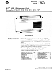
Artisan Technology Group is your source for quality
new and certified-used/pre-owned equipment
• FAST SHIPPING AND
DELIVERY
• TENS OF THOUSANDS OF
IN-STOCK ITEMS
• EQUIPMENT DEMOS
• HUNDREDS OF
MANUFACTURERS
SUPPORTED
• LEASING/MONTHLY
RENTALS
• ITAR CERTIFIED
SECURE ASSET SOLUTIONS
SERVICE CENTER REPAIRS
Experienced engineers and technicians on staff
at our full-service, in-house repair center
WE BUY USED EQUIPMENT
Sell your excess, underutilized, and idle used equipment
We also offer credit for buy-backs and trade-ins
www.artisantg.com/WeBuyEquipment
InstraView REMOTE INSPECTION
LOOKING FOR MORE INFORMATION?
Visit us on the web at www.artisantg.com for more
information on price quotations, drivers, technical
specifications, manuals, and documentation
SM
Remotely inspect equipment before purchasing with
our interactive website at www.instraview.com
Contact us: (888) 88-SOURCE | [email protected] | www.artisantg.com
PRODUCT
DATA
SLC TM 100 Programmable Controller
Processor Unit -Catalog Nos. 1745-LPI01, -LP102, -LP103, -LP104
The SLC 100
programmab/e
Contro"er
The SLC 100 Programmable Controlleris easy to program, using the
familiar ladder diagram format. Functional capabilities include relay
logic, timers, counters, sequencers, and shift registers. The controller can
be used in a wide variety of applications, including:
0
The PrOC@SSOr Unit
Machine tools
Material handling
0
0
Assembly machines
Molding and casting machines
Contains the processor (CPU and battery-backedCMOS RAM memory), a
power supply, and16 I/O circuits. It is available in four versions
to meet
various application requirements. Peripheral devices:
EEPROM Memory Module - Plugs into the processor unit
for
program loading and storage.
Pocket Programmer - Connect the programmerto the processor-unit to
program, monitor, edit, and troubleshoot. The nine operating modes
selected withthe programmer:
1: Clear Memory
2: Program
3: Run
4: Test-Single Scan
5: Test-Continuous Scan
6: Store Program in EEPROM
7: Load Program from EEPROM
8: EnteriChange Access Code
9: DiagnosticTest-Programmer
Personal Computer Software- Allows you to use
an IBM or IBMcompatible personal computer in place
of the pocket programmer. With
the software,you can select functions equivalent to the modes defined
above. Additional capabilities: off-line programming and program
library development; ladder diagram display and enhancements; data
display and cross reference table generation; program print-out. An
RS232-CIRS-422 interface converter is required
for communication between
the processor and computer.
Timer CounterAccess Terminal (TCAT)- Allows production, supervisory, and maintenance
people tomonitor programmed timer, counter,
and sequencer data
"on-line". Connected by cable to the processor
unit.
I/O Expansion Units - There are threeSLC 100 I/O expansion unitsthe basic expansion unit, the relay output expansion unit, and the analog
input expansion unit. These units can
be interconnected with the
processor unit to expand the number and type
of I/O circuits. You can also
connect theSLC 150 I/O expansion unit to the
SLC 100 processor unit.
The maximum numberof I/O circuits is112.
Publication 1745-2.1 -October, 1987
Supersedes Publication 1745-2.1 Dated August,1985
40065-230-01 (D)
Artisan Technology Group - Quality Instrumentation ... Guaranteed | (888) 88-SOURCE | www.artisantg.com
2
Processor Unit - SLC 100
The following features are pointed out in the illustration on 3.Page
1. Incoming line wiring terminals. Self-lifting pressure plates allow for
easy wire insertion and secure connections. Terminals accept
two #14
AWG wires. A hingedcover is provided (but not illustrated). The cover
needn’t be removed to gain access to the terminals.
2. Wiring terminalsfor 10 inputs. Same constructiona s line terminals.
The hinged cover (not illustrated) has write-on areas for identification
of external circuits. Cover is color-coded to identify the circuit voltage
level. The cover needn’t be removed to gain access to the terminals.
3. Wiring terminalsfor 6 outputs. Same constructionas line terminals.
Hinged cover (not illustrated) has write-on areas to identify external
circuits. The coverneedn’t be removed to gain access
to the terminals.
The processor unit has relay (hard contact) output circuits.
4. Five LED diagnostic indicators:
DC POWER (green) - Indicates that the processor unit is energized
and DC power is being supplied.
PC RUN (green) - Indicates the processor unit is in the Run
mode.
CPU FAULT (red) - Indicates the processor has detected
an error in
either the CPU or memory. Operation is automatically stopped.
BATTERY LOW (red) - A batteryprovides back-up powerfor the
CMOS RAM memory. This LED alerts you when the battery voltage
level has fallen
below a threshold level.
FORCED I/O (amber) - Indicates that one or more input or output
addresses have been
forced to an ON or OFF state.
5 . Input power fuse (behind front cover).
If line terminal voltage is
present but theDC POWER LED is not lit, the fuse may blown.
be
Refer tothe User’s Manualfor fuse replacement procedure.
6. Input status indicators. Ten red LEDs, identified with address
numbers 1 thru 10, corresponding to numbers1 thru 10 on the input
device wiring terminals. Whenan input circuit is energized, the
corresponding status indicator will
be lit.
7. Output status indicators. Six red LEDs, identified with address
numbers 11 thru 16, corresponding to numbers 11 thru 16 on the
output contact wiring terminals. When a programmed output
instruction is TRUE, the corresponding output status indicator
will be
lit, and the corresponding output contact
will close.
8. Auto/Manual switch. This switch controls restarting
of the processor
unit after power
a
loss,brown-out, or correction
of a CPU fault.
Auto - On power-up, the processor runs thru its normal diagnostic tests
and then automatically enters the Run
mode (ifit was in the Run
mode
at the last
power-down).
Manual - On power-up, the processor runs thru its diagnostic tests but
will not enter the Runmode. To enter the Run mode,you must move
the switchto the autoposition or use thepocket programmer (or
personal computer).
Artisan Technology Group - Quality Instrumentation ... Guaranteed | (888) 88-SOURCE | www.artisantg.com
3
Processor Unit - SLC 100
(*) Auto’manua1
switch.
Features
(continued)
(9) EEPROM memory
module
compartment.
\
(3) Wiring terminals
for 6 outputs.
indicators.
9. EEPROM memorymodulecompartment. The optional memory
module can be plugged into the processor. The pocket programmer or
personal computer software allows
you tostore your processorRAM
program in the EEPROM.You can also loada program from the
EEPROM into theDrocessor RAM.
We recommend that you install an EEPROM memory
module. This will provide maximum protection against user
program loss or program alteration due to battery back-up drain,
processor malfunction, or excessive noise.
10. Communication port. Thepocket programmer, interface converter, or
TCAT cableis plugged into this socket.
11. Expansion unit connection. The expansion unit cable is plugged in
.
this socket. SLC 100 and SLC 150 expansion units can be interconnected to increase the
I/O capacity of the controller.
12. Battery compartment. Back-up power for the CMOS RAM is
provided by a replaceable battery assembly, accessible from the front
of the processor unit. The lithium battery provides back-up
power for
approx. 2-3 years. Battery replacement: See the User’s Manual.
Artisan Technology Group - Quality Instrumentation ... Guaranteed | (888) 88-SOURCE | www.artisantg.com
4
Processor Unit - SLC 100
The enclosure should be adequate (NEMA approved) for the
environmental conditionsof the particular application.
The processor unit, expansion units, and inputloutput device circuits
should havethe samepower source. Theprocessor and expansion units
should be properly grounded.
Include a n electrical disconnect in the enclosure. An isolation
transformer may alsobe required.
A master control relay circuit should be included to permit disabling
of
the I10 devices independentof the processor and expansion unit power
circuit. One or more emergency-stop switches should also be included.
Follow recommendations for component spacing within the enclosure,
to help keepthe controller temperature within the specified limits.
Wiring should be routed to minimize electrical noise effects. Surge
suppressors should beused forinductive loads in series with hard
contacts and for other noise-generating equipment.
to protect loads and wiring from short
Fusing should be provided
circuits or overloading.
sslnting
1. Screw mounting: Theprocessor unit canbe mounted directlyto the
#10 screws. Hole locationsare
back panelof your enclosure using four
shown in the dimension drawing
below.
2. DIN rail mounting: The processor unit can be mounted in your
enclosure ona 35 mm by 7.5 mm DIN mounting rail (Catalog
No.
199-1DR). Two DIN rail fasteners are
provided on the processor unit,
The DIN rail canbe screwed, bolted,or welded tothe enclosure back
panel. Install the processor unit by hanging the unit on the top
of edge
the DIN rail, then pressing the unit toward the rail ituntil
snaps into
place. To remove theprocessor unit, pry open the fasteners.
Artisan Technology Group - Quality Instrumentation ... Guaranteed | (888) 88-SOURCE | www.artisantg.com
5
Processor Unit - SLC 100
Line Wiring
Connections
Makelineconnections as follows:
CAUTION: Incorrect wire connections can cause damage to the
processor unitpower supply. Do not jumper115VAC NEUT and
230VAC NEUT together. Do notjumper unused 115VAC NEUT or
unused 230VAC NEUT to the CHASSIS GND terminal.
Artisan Technology Group - Quality Instrumentation ... Guaranteed | (888) 88-SOURCE | www.artisantg.com
6
Processor Unit - SLC 100
put Wiring
connections
SLC 100 input circuitry is current sinking, compatible with current
sourcing (PNP) input devices. Circuitryincludesopticalisolationand
surge suppression to guard against damage
by transients from user input
devices.
A direct interface to solid state sensing devices and
SLC 100 controller
output circuitsis possible because of the 2 mA OFF state leakage current
specification, indicatedin thefollowing table. Note that the
2 mA value
applies only to inputs 1and 2 in someunits. You can achievea 2 mA
current valuefor inputs 3 thru 10by adding a resistor, as indicated.
Catalog
Number
1745-LP101
1745-LP102
1745-LP103
1745-LP104
Maximum OFF
State Leakage
Current
To achieve a 2 mA OFF state
leakage currentfor inputs 3
thru 10, connect a resistor
input
toterminal
the from
the COM terminal as shown
the
in
wiring
diagram.
2 mA, inputs 1
only
and
2
0
@
Input terminal coverplates are
color coded according to voltage:
115VAC -red, 230VAC -black, 24VDC -blue.
I
COM 1
4
I
2
3
I
4
5 COM 6
7
8
9 COM
10
4
4
COM terminals are connected together internally
COM terminals are connected together internally
1745-LP103, -LP104 (DC input devices)
1745-LP101, -LPI02
To achieve a 2 mA OFF state
leakage currentfor inputs3
thru 10, connect a resistor
from the inputterminal to
COM. 5.6K ohms, 112 watt
min.
I
I
I
COM terminalsare connected together internally
1745-LP103, -LP104 (AC input devices)
Artisan Technology Group - Quality Instrumentation ... Guaranteed | (888) 88-SOURCE | www.artisantg.com
7
Processor Unit - SLC 100
Output Wiring
Connections
Wiring connections for output devices are shown below. Note that the
diagram shows the internally-connected output contacts and parallelRC
networks. The RC networks guard against possible damageby transients
from external output devices.
External connectionsare shown for outputs11,15, and 16. We’ve added a
suppressor in parallel with two
of the external devices
for the purposeof
contact protection. Contact protectionis discussed on Page8.
Since the output contacts are isolated from each other, each output circuit
can be wired independently, with own
its ground return. You can applya
different voltage in each output circuit, as your application might require.
Power or ground wires can be jumpered betweenof sets
terminals if
desired.
You should provide appropriate fusing to protect the output devices and
wiring from short circuits and overload conditions.
I
Solenoid 15VAC 1
L l (Hi)
r
I
To limit theeffects of
leakage current, use a
loading resistor across
at
the load as shown
the right.
k
L2 (Lo)
5VAC 1
1
L1 (Hi)
Resistor
115VAC: 1 5 K o h r n , 2 w a t t
230VAC: 15K ohm, 5 w a t t
I
Artisan Technology Group - Quality Instrumentation ... Guaranteed | (888) 88-SOURCE | www.artisantg.com
I
8
Processor Unit - S l C 100
Output Contact
Protection
Inductive output devices suchas motor starters andsolenoids may
require thatyou use some type of surge suppression to protect the output
contacts. Examples are shownbelow.
These surge suppression circuits are connected directly across the output
can
device. The effect is to reduce arcingof the output contacts (arcing be
voltage which occurs whenan inductive
caused by the high transient
device is switched offp.
Suitable surge suppression methods for inductive
AC output devices
include a varistor, anRC network, and an Allen-Bradley surge
suppressor. These components must be appropriately rated to suppress
the switching transient characteristic
of the particular inductive device.
For inductive DC output devices,a diode is suitable.A 1N4004 diode is
acceptable for most applications. A surge suppressor can also
be used
(refer to the User’s Manual).
We recommend that you locate the suppression deviceas close as possible
to the outputdevice.
Suppressors recommended for use with Allen-Bradley relays, contactors,
and motor starters are listed in the User’s Manual.
Artisan Technology Group - Quality Instrumentation ... Guaranteed | (888) 88-SOURCE | www.artisantg.com
9
Processor Unit - SLC 100
General
Specifications
Shift Register: 8-bit groups.
Noise Immunity: NEMA Standard ICs 2-230.
Vibration: DIN Rail Mounting: 0.006 inch peak t o peak displacement, 1 .Og
peak (max) acceleration, 1 Hr/axis. Screw Fastener Mounting: 0.01 5 inch
peak t o peak displacement, 2.59 peak(max) acceleration,1 Hr/axis.
Ambient Temperature Rating: 0" t o 60" C (operating).
- 40"o 85"
C (storage).
Humidity Rating: 5 t o 95% (without condensation).
Wiring: #14 - #24 AWG stranded. 3/64" insulation (max).
Artisan Technology Group - Quality Instrumentation ... Guaranteed | (888) 88-SOURCE | www.artisantg.com
10
Processor Unit - SLC 100
Input SpeCifkatiOnS
Input specifications for the various processor unit versionsare shown below.
to
The 2 mA OFF state leakage current specification allows direct interface
solid state sensing devices.
Note that the mA
2 OFF state leakage current for
24VAC circuits applies to
inputs 1and 2 only. When required,
you can also achieve 2a mA OFF state
leakage currentfor inputs 3 thru 10, as indicated in the specifications.
All input circuits include optical isolationwell
as as filtering and surge
by transients from external input
suppression to guard against damage
devices.
ON State Voltage Range and Frequency:
1745-LP101: 85-1 32VAC, 50/60 HZ.
1745-LP102: 170-265 VAC, 50/60 HZ.
1745-LP103, -LP104: 10-30V, AUDC.
Maximum OFF State Voltage:
1745-LP101:35V.
1745-LP102:
50V.
1745-LP103, -LP104: 5V.
'
Maximum OFF State Leakage Current:
1745-LP101,-LP102: 2 mA.
1745-LP103, -LP104: ZmA, inputs 1 and 2 only. To achieve a 2
mA 0,FF state leakage current for inputs 3 thru 10, connect a
5.6KO, 1/2 watt (min) resistor from the input
terminal to the
common terminal.
Nominal Input Current:
1745-LP101, -LP102: 8 mA.
1745-LP103, -LP104: Inputs 1 and 2- 8 mA a t 12V, 18 mA a t 24V.
Inputs 3 thru 10- 6 mA a t 12V, 14 mA at 24V.
Specifications applying t o all Catalog Numbers:
input Filter Time Delay: 10-25 msec.
Electrical-Optical Isolation:
1500 volts between input voltage and control logic.
Artisan Technology Group - Quality Instrumentation ... Guaranteed | (888) 88-SOURCE | www.artisantg.com
11
Processor Unit - SLC 100
eationS
Output specifications for all versionsof the processor unit are shown
below.
Internal output circuitry includes surge suppression
to guard against
possible damage by transients from external outputdevices. We
of contact protection when
recommend that you also use some type
switching inductive load devices. Refer to Pages 7 and 8.
Voltage Range and Frequency:
10-250 VAC (50/60 HZ), 10-125 VDC.
Contact Ratings:
240VAC
l2OVAC
0.75A 7.5A
2,5A
1.5A 15A
1800VA
180VA
125VDC
0.22A
1 .OA
28VA
24VDC
1.2A
2.5A
28VA
Contact Resistance: 20 mR (typical).
Electrical Isolation: 2000 volts.
OFF State Leakage Current: 2 mA (AC voltage only). To limit
leakage current use a loading resistor across the loadas
shown on Page7.
Output Fusing for OverloadProtection:
Bussman 3A, 250VACslow blow or equivalent.
Internal RC Network Values: R = 120 ohms, C = 0.022 microfarad.
Artisan Technology Group - Quality Instrumentation ... Guaranteed | (888) 88-SOURCE | www.artisantg.com
ALLEN-BRADLEY
A ROCKWELL INTERNATIONAL COMPANY
industrial Control Group
Milwaukee, Wisconsin 53204
Artisan Technology Group - Quality Instrumentation ... Guaranteed | (888) 88-SOURCE | www.artisantg.com
Artisan Technology Group is your source for quality
new and certified-used/pre-owned equipment
• FAST SHIPPING AND
DELIVERY
• TENS OF THOUSANDS OF
IN-STOCK ITEMS
• EQUIPMENT DEMOS
• HUNDREDS OF
MANUFACTURERS
SUPPORTED
• LEASING/MONTHLY
RENTALS
• ITAR CERTIFIED
SECURE ASSET SOLUTIONS
SERVICE CENTER REPAIRS
Experienced engineers and technicians on staff
at our full-service, in-house repair center
WE BUY USED EQUIPMENT
Sell your excess, underutilized, and idle used equipment
We also offer credit for buy-backs and trade-ins
www.artisantg.com/WeBuyEquipment
InstraView REMOTE INSPECTION
LOOKING FOR MORE INFORMATION?
Visit us on the web at www.artisantg.com for more
information on price quotations, drivers, technical
specifications, manuals, and documentation
SM
Remotely inspect equipment before purchasing with
our interactive website at www.instraview.com
Contact us: (888) 88-SOURCE | [email protected] | www.artisantg.com