1
Invacare® Spinx
User Manual
English
1
Contents
Product description ......................................................... 3
NB! ...................................................................................... 4
Lifting the wheelchair ...................................................... 4
Intended use ...................................................................... 5
Daily performance check ............................................... 5
Upholstery and frame colours ...................................... 6
Equipment and accessories ............................................ 6
Technical data ................................................................... 7
Before first use:
Delivery check .................................................................. 8
Assembly ............................................................................ 8
Adjustments:
Legrests ............................................................................ 10
Calf pads/Footplates ...................................................... 11
Seat .................................................................................... 12
Backrest............................................................................ 13
Armrests/mudguards ..................................................... 16
Rear wheels .................................................................... 17
Castor wheels ................................................................. 19
Brakes ............................................................................... 20
Anti-tip devices ............................................................... 21
Wheelchair heights ........................................................ 22
Accessories:
Amputee legrest ............................................................. 26
External push handles ................................................... 26
Pelvic belt ......................................................................... 26
Transport:
Transport ......................................................................... 27
Transport of wheelchairs in vehicles .......................28
To observe......... ............................................................. 30
Restraint methods ........................................................ 31
Safety instructions/propelling techniques ................32
Service:
Guarantee ....................................................................... 34
Maintenance .................................................................... 34
Recycling ......................................................................... 35
©Invacare Rea AB
Every effort has been made to ensure that the contents
of this publication are updated at the time of printing.
As part of the ongoing improvement of the products,
Invacare Rea AB reserves the right to modify existing
models at any time.
Any use of this publication, or parts thereof, as well
as any reproduction of images, must have the written
consent of Invacare Rea AB
2
INVACARE® SPINx
Product description
Invacare® Spinx
Invacare® Spinx is a wheelchair with many adjustment
options and accessories. To ensure that you benefit as
much as possible from your Invacare® Spinx, and in order
to do its options justice, the chair must be tested and
adjusted by competent personnel. We hope that you have
also received instructions for using your Invacare® Spinx
in everyday life.
The Invacare® Spinx frame, legrests and hand rims are
manufactured from high quality aluminium.
Vulnerable parts, the telescopic backrest tubes and the
inner part of the legrest tubes, are made from steel.
The seat cushion is made of Jemima and the backrests are
in Jemima or nylon. The padded seat is made of nylon.
This manual includes a description of the parts of the chair,
simple adjustment options, how to use the Invacare® Spinx
safely and how to transport it. The manual must be read
thoroughly before the chair is used.
Also included in this manual is a description of how the
most common accessories are fitted and slightly more
advanced settings.
As the Invacare® Spinx has many different components and
accessories, the appearance of the accessories you have
for your chair may differ from those shown.
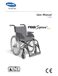
Parts of the wheelchair
4
3
12
11
5
1
6
13
7
10
8
1.
2.
3.
4.
5.
INVACARE® SPINx
Frame (chassis)
Cross members
Backrest
Push handles
Seat
2
14
6.
7.
8.
9.
10.
Rear wheel
Handrims
Brakes
Castors
Anti tip device
11.
12.
13.
14.
Armrests
Sideguards
Legrests
Footplate
3
NB!
This symbol means warning.
On this page a number of points affecting your personal safety are
shown. Please Read it carefully!
Invacare® is only responsible for product changes carried out by personnel who we authorise. We reserve the right to make any changes
to equipment and specifications without prior notice.
Failure to comply with instructions given may result in personal injury
and/or product damage.
- that all parts are attached securely to the frame
- that all wheels and knobs are properly tightened
- that all brakes and anti-tip devices function correctly
backrest stay or by the adjustable push handles.
because of the risk of tipping.
over.
"
injury to your hands.
#$%
& %
is reduced in wet and slippery conditions, as well as when on a
slope.
'
*
chair.
" + :
greater the risk of tipping the wheelchair becomes.
;
long time exposure to sun reach temperatures over 41 °C.
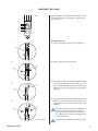
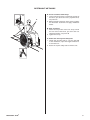
LIFTING THE WHEELCHAIR
Always lift the wheelchair by gripping
the frame at the points shown in the
diagram. Never lift the wheelchair by
the removable armrests or the footrests. Ensure that the backrest and push
handles are securely in place. Also read
the chapter Safety instructions/Propelling techniques.
4
INVACARE® SPINx
Intended use
?® Spinx is a manual wheelchair aimed for those who use
the wheelchair during a longer period of time (several hours in a
row).
?® Spinx is designed for the user who can manoeuvre the
wheelchair them-selves and as well for the user that requires assistance.
?® Spinx have abilities and accessories that make it possible
to adjust the sitting posture so it becomes comfortable and possible
to keep for several hours.
?® Spinx have many adjustment possibilities. With the right
adjustments, carried out by a professional the wheelchair can be
set up more specific to the user and assistants requirements. The
possible adjustments are described in the Owners Manual that is
delivered together with the wheelchair.
*
@
KQXX%YXXZ
?®
Spinx be used both indoor and outdoor. We recommend the larger
wheels when the wheelchair is used on un-even ground.
?® Spinx may tip over, backwards, when being
wheeled uphill, especially when the incline is more than 8° or if the
rearwheels are mounted more forward on the rearwheel attachment. The effect of having the rear wheel fitted in the most forward
position is that the chair will be easier to manoeuver, there is a
however an increased risk of tipping backwards, therefore the use of
anti tippers are recommended in this case. Use the Anti tip devises
when there is a risk of that the chair will tip over and to achieve a
higher stability.
?® Spinx is designed to have a seat cushion on the seat.
The seat cushion improves the body posture by the user and makes
it possible to sit comfortable for a longer period of time in the
wheelchair.
Daily performance check
Check that the following parts are securely fitted on the wheelchair
INVACARE® SPINx
<
'
%
=
>
'
5
Upholstery and frame colours
Upholstery
Black Nylon TR33, Black Jemima TR18
Frame colours
Blue, Red, Black, Grey (Limegreen and orange as special)
Equipment and accessories
Invacare® Spinx has a wide range of accessories and options.
6
Backrest
Slingtype
Tension adjustable
Backrest bar
Mistral2 cushion
Seat
Sling seat depth adjustable 5 cm
Padded seat
Tension and depth adjustable seat
Seat cushions
Standard 5 cm
Legrests
80º & 90º fixed legrest
Angle-adjustable legrest
Amputee legrest
Fixed footplate
Angle- and depth adjustable footplate
One piece footrest
Heel straps
Calf strap
Armrests
Flip-up armrest
Height adjustable armrest
Long or short pad
Autolocking
Castors
100-200 mm, pneumatic or solid, wide or narrow
Rear wheels
22", 24", pneumatic or puncture-proof
Brake
User-brake
Carer-operated brake
Extended brake arm
One-arm brake
Others
Several types of handrims
Spoke guard
Anti-tip devices
Reflectors Kit
Table Tray
Pump
Cane holder
Tool kit
External push handles
Pelvic belt
Mudguard
Sideguard
Step tube
INVACARE® SPINx
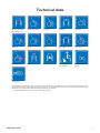
Technical data
38, 40.5, 43, 45.5,
48**, 50.5** cm
40, 45, 50 (-5) cm
41-53 cm
35-49 cm
19–29 cm
32-58 cm
0°– 6°
±12°
Seat width + 21 cm
76-113 cm
80-126 cm
29 cm
13 kg
max 125 kg
max 135 kg**
7,5 kg
Transport weight
Crash test*
*Our wheelchairs comply with ISO norm 7176-19 and have been tested in a basic configuration. The use in other configurations has not been
tested. See section "Test report from dynamic safety restraint test", for test configuration. Wheelchair users should however transfer to the
vehicle seat and use the vehicle installed restraint system whenever it is feasible
** For seat widths 48 and 50,5 cm the maximum user weight is 135 kg.
INVACARE® SPINx
7
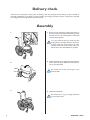
Delivery check
Check that all components comply with the delivery note. Any damage incurred during transport should be
reported immediately to the delivery company. Retain all packaging until the transport company has inspected
the consignment and an agreement has been reached.
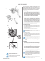
Assembly
1.
1. Attach the rear wheels by pressing the button in
the centre of the hub whilst simultaneously sliding
the axle into the rear wheel position attachment
of the positioning plate.
It is very important that you check that the
locking pin has actually locked the wheel into
position when the centre button has been
released. Take hold of the wheels and try to
detach them. This should NOT be possible.
2.
2. Unfold the backrest by pulling backrest backward
until it clicks into place. Make sure that the backrest is securely locked.
Be careful not to trap your fingers in the
backrest links.
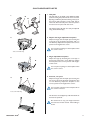
3.
3. Unfold the wheelchair.
Be careful not to trap your fingers between
seat and frame tube.
8
INVACARE® SPINx
4.
4. Insert the armrest by fitting it into the attachment
on the backrest frame and then swing it down until
it fits into position.
Do not place any fingers on the seat frame.
When having detachable armrests, just press
them down in the reciver.
5.
5. Legrests
Attach the legrests by pushing the tube at the
upper part of the legrests down into the tubes on
the wheelchair. You must angle the legrestsoutwards when inserting them.
Lock the legrests by turning them inwards. The
legrests are automatically locked so there is no
risk of them coming off the wheelchair.
Be careful not to trap your fingers between
frame and legrest.
INVACARE® SPINx
9
Adjustments
ANGLE ADJUSTABLE LEGRESTS
1.
Angle adjustable legrests support the legs and reduce
pressure. The legrests can be used for bandaged legs,
but not for legs in plaster casts. The legrests must
always be fitted with calf pads, footplates and heel
straps.
B
It is important to adjust the height and angle of the
legrests to obtain a good seating position.
1. Height adjustment
Loosen screw (A) with an Allen key. Adjust the
legrest into a suitable height and the screw is
caught by one of the recesses on the legrest tube.
Then retighten the screw.
A
"
z{
2. Angle adjustment
Pull the lever (B) with one hand while supporting the legrest with your other hand. When a
suitable angle is obtained, let go of the lever and
the legrest will look into one of seven preset
positions (C).
2.
B
Do not place anything heavy, or let children
sit on the legrest. It may cause damage to the
mechanism.
C
The distance between the lowest part of
the footrest and the ground must be at least
40 mm.
FIXED LEGRESTS
C
A
Height adjustment
Loosen screw (A) with an Allen key. Adjust the legrest
into a suitable height and the screw is caught by one
of the recesses on the legrest tube. Then retighten
the screw.
NOTE! Don't touch the upper screw (C).
The distance between the lowest part of
the footrest and the ground must be at least
40 mm.
"
z{
10
INVACARE® SPINx
CALF PADS/FOOTPLATES
C
1.
D
B
1. Calf pads
The calf pads can be fitted in four different depth
positions. Swing the pad forwards. Unscrew screw
(B) using an Allen key. Remove the large nut (C) on
the reverse side and place it in the other attachment hole. Move the calf pad to the new position
and secure it into place with the screw.
The height of the calf pads can easily be adjusted
using the handwheel (D).
2.
2. Depth- and angle adjustable footplates
Adjust the angle and the depth by loosening the
screw (A) at the footplate attachment with a 5
mm Allen key. Adjust the footplate to the correct
position and retighten the screw.
Do not place anything on the footplate when
the screw is loose.
A
"
z{
3.
A
3. Angle adjustable footplates
Adjust the angle by loosening the screw (A) on
the footrest tube with a 5 mm Allen key. Adjust
the footplate to the correct position and retighten the screw.
Do not place anything on the footplate when
the screw is loose.
4.
A
4. Footrest, one piece
Adjust the angle and the depth by loosening the
two screws (A) at the footplate attachment with
a 5 mm Allen key. Adjust the footplate to the
correct position and retighten the screws.
Do not place anything on the footplate when
the screws are loose.
"
z{
The footrest can be flipped up. Lift the left side of
the footrest upwards.
Be careful not to trap your fingers between
the footrest and the reciever when folding it
down.
INVACARE® SPINx
11
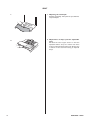
SEAT
1.
2.
12
1. Adjusting the seat depth
Fold the seat slightly. Lift up the rear part. Pull into
required depth.
2. Adjustment of shape (tension adjustable
seat)
= + adjustable Velcro straps are visible. Use these
straps to adjust the shape of the seat. Always have
a cushion on the seat when testing its adjusted
shape.
INVACARE® SPINx
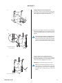
BACKREST
1.
Height adjustment, fixed backrest.
1. Use a pair of scissors and remove the plastic ties
(A) at the bottom of the backcloth. Then fold the
chair slightly, by lifting the seat upwards.
A
2.
2. Remove screws (B) on the back of the backrest
tube with an Allen key. It is now possible to lower
and raise the back. Fasten the screws and nuts and
tighten.
C
When adjusting the height, the embossed mark
(C) on the backrest tube must NEVER be visible above the frame tube. Otherwise the backrest may come loose and cause serious injury.
Make sure that the backrest is safely secured.
"
z
10 mm spanner
B
1.
Height adjustment, foldable backrest.
1. Loosen screws (C) on the back of the backrest
tube with an Allen key. It is now possible to lower
and raise the back. Retighten the screws.
NOTE! Don't touch the lower screws (D).
When you have fitted the backrest in the correct position, it is important that you check
thoroughly that the screws are tightened
securely. This is important for your own
safety!
C
"
z
INVACARE® SPINx
D
13
TENSION ADJUSTABLE BACKREST
Adjustment of backrest height
1. Detatch the left hand side of the back brace by
depressing the catch on the inside of the left hand
bracket and then rotate the brace downwards.
Fold the chair slightly by taking hold of the the
seat and pulling upwards. Then loosen and fold the
backcloth forward, so that it rests on the seat.
1.
2. Slacken the screws (A) on the rear of the back
tube, using an Allen key. It is now possible to
raise or lower the back and then retighten the
screws.
2.
"
z
3.
A
Adjustment of backrest tension
3. Adjust the shape of the backrest by adjusting the
Velcro straps.
The user should be seated in the chair and the
back brace should be in place when adjusting the
Velcro straps. When adjustment is complete fold
the backcloth back into position and secure it with
the Velcro straps.
When you loosen the backrest, the tip-risk
increases. We recommend the use of anti-tip
devices.
4.
14
4. Please observe that the backrest bar may not be
used for lifting the chair!
INVACARE® SPINx
BACKREST RECLINE
When the Spinx is equipped with a foldable backrest,
the backrest angle can be adjusted in angles from 0 °
to ±12° (pic. A).
A.
3°
6°
9°
12°
0°
Angle adjustment
1. Loosen the screw (a) using an 5 mm Allen key.
1.
b.
2. Remove the screw (a) and nut (b).
2.
a.
b.
3.
c.
d.
4.
a.
b.
4. To lock the backrest tube, first place the nut (b) in
it's slot on the lower tube, then attach the screw
(a) and tighten. Make sure that the backrest is still
foldable.
Note that when the backrest is angled backwards, it also increases the risk of tipping
the chair backwards. Adjust the rear wheels
to a stable position. We recommend the use
of anti-tip devices.
"
z
INVACARE® SPINx
3. The backrest tube can now be angled forward
or backward. Place the upper tube (c) in the
desired angle and make sure that one of the angle
holes (A) is visible through the hole in the lower
tube (d).
Make sure that the backrest is safely secured.
15
ARMRESTS/MUDGUARD
Adjusting the height of the armrests
1. Flip up armrest
If your chair is equipped with armrests that can be
raised or lowered, this is achieved by loosening the
screw (A), moving the armrest into the required
position and retightening the screw.
1.
When adjusting the height, do not place your
fingers between armrest pad and side plate as
they may get trapped.
A
"
z
2. Detachable armrest
If your chair is equipped with armrests that can
be raised or lowered, this is achieved by pulling
up the armrest and loosening the screw (B) under
the armrest. Move the screw up or down to the
desired position and retighten the screw. Lower
the armrest again.
2.
When adjusting the height do not place your
fingers between seat tube and side plate as they
may get trapped.
B
"
z
3-4.
D
E
C
"
}
5 mm Allen key
16
3. Mudguard
Adjust the height of the mudguard by pulling up
the mudguard and loosening the screw (C). Move
the screw up or down to the desired position and
retighten the screw. Insert the mudguard again in
it's attachment.
When adjusting the height do not place your
fingers between seat tube and side plate as they
may get trapped.
4. To adjust the depth of the mudguard, unscrew
screws (D) using an Allen key. Remove the nuts (E)
on the reverse side. Move the mudguard into the
required position and fasten the screws again.
INVACARE® SPINx
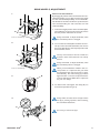
REAR WHEELS, ADJUSTMENT
Active rear wheel fixation
By changing the position of the rearwheel on the rearwheel attachment you can alter both the seat height
and the manoeuvrability/stability of the wheelchair.
The further forward the rearwheel is positioned, the
more manoeuvrable your chair becomes, but with
reduced stability.
1.
1. To alter the height position of the rearwheel plate,
use an Allen key to remove the screws (A), choose
the new position and fasten the screws.
A
Always remember to adjust the brakes, when
the rearwheel position is changed.
"
z{
2.
2. To move the rearwheel (either backwards or forwards) on the rearwheel attachment, first remove
the screws (B), adjust to the required position and
then fasten the screws.
The tip risk increases if the rear wheels are
located in front of the backrest. Use anti-tip
devices.
D
B
C
Always remember to adjust the brakes, when
the rearwheel position is changed.
"
z{
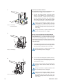
3.
D
When you have fitted the wheels in the correct position, it is important that you check
thoroughly that the nuts and screws are tightened securely. The axle housing (C) must be
tightened with a manual and dynamometric
wrench calibrated to 40Nm.This is important
for your own safety!
3. To obtain lower seat heights, the clamp (D) can
be mounted upside down (pic 3).
4.
F
Always make sure that the arrow (E) and the
line (F) is pointing upwards, when mounting
the rearwheel attachment.
E
Do not try to loosen nut (G)!
G
INVACARE® SPINx
17
Passive rear wheel fixation
By changing the position of the rear wheel fixation you
can alter the seat height of the wheelchair.
1.
1. To alter the height position of the rear wheel
fixation, use an Allen key and a fixed spanner to
remove the screws , washers and nuts. Choose
the new position and fasten the screws again.
Note that the holes (A) are the reference holes
$
~
@
A
When you have fitted the wheels in the correct position, it is important that you check
thoroughly that the screws and nuts are
tightened securely. This is important for your
own safety.
"
z
10 mm fixed spanner
Always remember to adjust the brakes, when
the rear wheel position is changed.
2.
Active rear wheel fixation with drumbrake
By changing the position of the rearwheel on the rearwheel attachment you can alter both the seat height
and the manoeuvrability/stability of the wheelchair.
The further forward the rearwheel is positioned, the
more manoeuvrable your chair becomes, but with
reduced stability.
A
2. To alter the height position of the rearwheel plate,
use an Allen key to remove the screws (A), choose
the new position and fasten the screws again.
Always remember to adjust the brakes, when
the rearwheel position is changed.
"
z{
3.
B
3. To move the rearwheel (either backwards or forwards) on the rearwheel attachment, first remove
the screws (B), adjust to the required position and
then fasten the screws.
The tip risk increases if the rearwheels are
located in front of the backrest. Use anti-tip
devices.
Always remember to adjust the brakes, when
the rearwheel position is changed.
"
z{
18
When you have fitted the wheels in the correct position, it is important that you check
thoroughly that the nuts and screws are
tightened securely. This is important for your
own safety!
INVACARE® SPINx
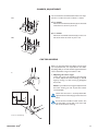
CAMBER, ADJUSTMENT
You can mount the rearwheel attachment in two ways.
One for 0° camber and one to obtain 3° camber.
3a.
A
3a. 0° camber
Mount the rearwheel attachment (A) on the inside
of the frame as shown in picure 3a.
3b. 3° camber
Mount the rearwheel attachment (A) on the outside of the frame as shown in picure 3b.
3b.
A
CASTOR WHEELS
When you have found the seat height and seat angle
+
propelling ability to control that the angle between the
castor attachment and ground surface is 90°.
1.
1. Adjusting the castor angle.
Loosen the screws (A) and (B) by approximately
2–3 turns. Adjust the castor housing to desired
angle by turning it to the correct jag. Retighten
the screws.
Note! It is possible to have negative adjustment of
the castor housing (-3° and -6°) but this is NOT
recommended!
A
Check that the castor is securely fitted after
replacement and that the jags lockes into each
other.
0°
3°
6°
Do not loosen screw B more than 5 turns. The
corresponding nut will then come loose and
fall out of the castor housing.
"
z
B
INVACARE® SPINx
19
BRAKES
C
1.
X
MA
A
To apply the brake to the chair, move the lever (A)
forwards. To release the brake, move the lever
backwards (towards you).
Take care not to trap your fingers between
the brake shaft and tyre.
B
C
X
MA
B
Adjusting the brake
1. Check that the tyres are inflated to the correct air
pressure (indicated on the tyre wall). Then, using
an Allen key, loosen the screw and slide the brake
to the desired position and tighten. The correct
distance between the brake shaft (B) and the tyre
is approx. 15 mm.
NB.
The brake must not be moved further than indicated in the picture (C).
"
z
Incorrect adjustments or use of the brake can
reduce the effectiveness of the brake.
Free play
The lever of the brake where the handle is located,
have a free play. The lever folds up automatically
when the legrest have been swinged to its outward
position without activating the brake. To activate the
brake just press respectively pull at its most forward
respectively rear located position.
The reason behind is that when the legrests is
swinged to the side it will in some positions interfere
with the brake lever.
CARER-OPERATED BRAKE
1.
1. K@ Z brake will be applied.
2.
2.
move the lock catch (A) upwards. Then release
the handle.
A
3.
3. &
the lock catch will release automatically.
Incorrect adjustments or use of the brake can
reduce the effectiveness of the brake.
20
INVACARE® SPINx
ANTI-TIP DEVICES
B
1a.
A
The anti-tip device is foldable and adjustable in both
height and depth. Please pay special attention to the
placement of the anti-tip device when in use. A sticker
will warn you if the anti-tip device is not activated.
1. Mounting
a. Insert the two shorter screws into the holes in
the rear part of the chassis according to picture 1a.
Place the two spacers (B) on the screws. Note that
the curved surface should be towards the tube. Fit
the anti-tip device on the screws and tighten.
1b.
C
B
A
2-4.
E
b. Remove the back screw and nut on the rear
wheel attachment and discard them. Mount the
longer screw (C) through the rear wheel attachment according to picture 1b. Put the shorter screw
(A) into the hole in the rear part of the chassis. Place
one spacer (B) on the shorter screw (A) Note that
the curved surface should be towards the tube. Fit
the anti-tip device and tighten the screws.
2. Adjusting height
To adjust the height press the two knobs (B) on
each side of the housing and pull the tube (C) to
desired set of holes.
The knobs will lock the tube into position.
Do not use knobs (B) to fold or unfold the
anti-tip device.
B
3. Adjusting depth
To adjust the depth press knob (D) and pull the
wheel tube out to desired depth. The knob will lock
the tube into position.
C
The distance between the anti-tip wheel and
the ground, and the distance between the antitip wheel and rear wheel, should be approx.
5 cm.
4. Folding
To swing the anti-tip device under the wheelchair,
press the cap (E) downwards and then sideways.
NOTE! A red warning sticker can now be seen.
D
To activate the anti-tip device, just swing it back in
place and it will lock into position automatically.
NOTE! When the anti-tip device is correctly activa
ted the warning sticker will be hidden.
Make sure the anti-tip device is
securely locked before use.
For safety reasons we recommend the
use of two anti-tip devices!
INVACARE® SPINx
Use your foot when folding the anti-tip device. If
you do it by hand, there is an increased risk that
you will trap your fingers between the anti-tip
housing and the tube.
Never forget to fold down the anti-tip devices
or the wheelchair may tip over.
21
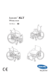
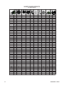
WHEELCHAIR HEIGHTS
22" Rear wheel
5
4
3
2
1
75
5
4
3
2
1
SD
150
110
12 34
4
3
2
1
4
3
2
1
H mm
X°
X"
pos.
pos.
pos.
pos.
pos.
mm
SD40
SD45
SD50
410
410
410
0
3
6
22
22
-
-
2
3
-
2
2
-
-
-
100
100
-
1,2,3,4
1,2,3,4
-
1,2,3,4
1,2,3,4
-
1,2,3,4
1,2,3,4
-
430
430
430
455
455
455
455
455
455
455
455
455
480
480
480
480
480
480
480
480
480
480
480
480
505
505
505
505
505
505
505
505
505
505
505
505
505
505
505
505
505
505
505
505
505
0
3
6
0
3
6
0
3
6
0
3
6
0
3
6
0
3
6
0
3
6
0
3
6
0
3
6
0
3
6
0
3
6
0
3
6
0
3
6
0
3
6
0
3
6
22
22
22
22
22
22
22
22
22
22
22
22
22
22
22
22
22
22
22
22
22
22
22
22
22
22
22
22
22
22
22
22
22
22
22
22
22
22
22
-
4
4
5
1
2
3
1
2
1
-
1
1
1
-
2
3
3
3
3
3
3
3
1
1
1
1
1
1
1
1
1
-
-
100
100
100
120
120
120
140
140
140
150
150
100
100
120
120
120
140
140
140
150
150
100
100
100
120
120
120
140
140
150
150
150
180
180
180
180
180
180
200
-
1,2,3,4
1,2,3,4
1,2,3,4
1,2,3,4
1,2,3,4
1,2,3,4
1,2,3,4
1,2,3,4
1,2,3,4
1,2,3
1,2,3
1,2,3,4
1,2,3,4
1,2,3,4
1,2,3,4
1,2,3,4
1,2,3,4
1,2,3,4
1,2,3,4
1,2,3,4
1,2,3,4
1,2,3,4
1,2,3,4
1,2,3,4
1,2,3,4
1,2,3,4
1,2,3,4
1,2,3,4
1,2,3,4
1,2,3
1,2,3
1,2,3
1,2
1,2
1,2
1,2
1,2
1,2
-
1,2,3,4
1,2,3,4
1,2,3,4
1,2,3,4
1,2,3,4
1,2,3,4
1,2,3,4
1,2,3,4
1,2,3,4
1,2,3,4
1,2,3,4
1,2,3,4
1,2,3,4
1,2,3,4
1,2,3,4
1,2,3,4
1,2,3,4
1,2,3,4
1,2,3,4
1,2,3,4
1,2,3,4
1,2,3,4
1,2,3,4
1,2,3,4
1,2,3,4
1,2,3,4
1,2,3,4
1,2,3,4
1,2,3,4
1,2,3,4
1,2,3,4
1,2,3,4
1,2,3,4
1,2,3,4
1,2,3,4
1,2,3,4
1,2,3,4
1,2,3,4
1,2,3,4
-
4
5
3
5
3
4
5
2
4
5
2
3
1
3
4
1
2
4
2
4
1
2
3
1
2
3
1
2
3
1
-
3
3
4
4
4
1
1
1
2
2
2
3
3
3
3
3
4
4
4
-
- = Not applicable
22
INVACARE® SPINx
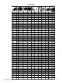
24" Rear wheel
5
4
3
2
1
- = Not applicable
75
5
4
3
2
1
SD
150
110
12 34
4
3
2
1
4
3
2
1
H mm
X°
X"
pos.
pos.
pos.
pos.
pos.
mm
SD40
SD45
SD50
410
0
24
-
4
2
-
-
100
1,2,3,4
1,2,3,4
1,2,3,4
410
3
24
-
5
2
-
-
100
1,2,3,4
1,2,3,4
1,2,3,4
410
6
-
-
-
-
-
-
-
0
24
-
1
-
-
100
-
430
3
1,2,3,4
1,2,3,4
1,2,3,4
430
3
24
-
4
1
-
-
100
1,2,3,4
1,2,3,4
1,2,3,4
430
6
24
-
5
1
-
100
1,2,3,4
1,2,3,4
1,2,3,4
430
0
24
-
-
4
-
120
1,2,3,4
1,2,3,4
1,2,3,4
430
3
24
-
2
4
-
4
-
120
1,2,3,4
1,2,3,4
1,2,3,4
430
6
24
-
5
-
4
-
120
1,2,3,4
1,2,3,4
1,2,3,4
455
0
-
-
-
-
-
-
-
-
-
-
-
3
-
120
1,2,3,4
1,2,3,4
1,2,3,4
455
3
24
-
455
6
24
-
3
4
455
0
24
-
1
-
3
-
120
1,2,3,4
1,2,3,4
1,2,3,4
-
3
-
140
1,2,3,4
1,2,3,4
1,2,3,4
455
3
24
-
2
-
3
-
140
1,2,3,4
1,2,3,4
1,2,3,4
455
6
24
-
3
-
3
140
1,2,3,4
1,2,3,4
1,2,3,4
480
0
-
-
-
-
-
-
-
-
-
-
480
3
24
-
1
-
1
-
120
1,2,3,4
1,2,3,4
1,2,3,4
480
6
24
-
2
-
1
1,2,3,4
1,2,3,4
1,2,3,4
0
24
5
-
-
-
4
120
480
120
1,2,3,4
1,2,3,4
1,2,3,4
480
3
-
-
-
-
-
-
-
-
-
-
480
6
24
-
2
-
4
1,2,3,4
1,2,3,4
0
24
4
-
-
4
120
140
1,2,3,4
480
-
1,2,3
1,2,3,4
1,2,3,4
480
3
24
5
-
-
-
4
140
1,2,3
1,2,3,4
1,2,3,4
480
6
-
-
-
-
-
-
-
-
-
-
480
0
24
4
-
-
1
-
150
1,2,3,4
1,2,3,4
1,2,3,4
1,2,3,4
480
3
24
5
-
-
1
-
150
1,2,3,4
1,2,3,4
480
6
-
-
-
-
-
-
-
-
-
505
0
24
3
-
-
-
1
100
1,2,3,4
1,2,3,4
1,2,3,4
505
3
24
4
-
-
-
1
100
1,2,3,4
1,2,3,4
1,2,3,4
505
6
24
5
-
-
-
1
100
1,2,3,4
1,2,3,4
1,2,3,4
505
0
24
3
-
-
-
2
120
1,2,3,4
1,2,3,4
1,2,3,4
505
3
24
4
-
-
-
2
120
1,2,3,4
1,2,3,4
1,2,3,4
505
6
24
5
-
-
-
2
120
1,2,3,4
1,2,3,4
1,2,3,4
505
0
24
2
-
-
-
140
1,2,3
1,2,3,4
1,2,3,4
505
3
24
3
-
-
-
2
2
140
1,2,3
1,2,3,4
1,2,3,4
505
6
-
-
-
-
-
-
-
-
-
-
505
0
24
3
-
-
-
3
150
1,2,3
1,2,3,4
1,2,3,4
505
3
24
4
-
-
-
3
150
1,2,3
1,2,3,4
1,2,3,4
505
6
24
5
-
-
3
1,2,3,4
1,2,3,4
0
24
3
-
-
-
150
180
1,2,3
505
1
-
1,2
1,2,3,4
505
3
24
4
-
-
1
-
180
-
1,2
1,2,3,4
505
6
-
-
-
-
-
-
-
-
-
505
0
24
3
-
-
-
4
180
1
1,2,3
1,2,3,4
-
4
180
1
1,2,3
1,2,3,4
4
180
1
1,2,3
1,2,3,4
-
200
200
*
1,2
1,2,3,4
-
*
1,2
1,2,3,4
-
-
-
-
-
-
-
-
-
-
-
-
-
-
1
140
1,2,3
1,2,3,4
1,2,3,4
-
-
-
1
140
1,2,3
1,2,3,4
1,2,3,4
-
-
-
1
150
1,2,3
1,2,3,4
1,2,3,4
2
-
-
-
1
150
1,2,3
1,2,3,4
1,2,3,4
24
3
-
-
-
1
150
1,2,3
1,2,3,4
1,2,3,4
0
24
1
-
-
-
2
180
1
1,2,3
1,2,3,4
530
3
24
2
-
-
-
2
180
1
1,2,3
1,2,3,4
530
6
24
3
-
-
-
2
180
1
1,2,3
1,2,3,4
530
0
24
1
-
-
-
3
200
*
1,2
1,2,3,4
530
3
24
2
-
-
-
3
200
*
1,2
1,2,3,4
530
6
24
3
-
-
-
3
200
*
1,2
1,2,3,4
505
3
24
4
-
-
505
6
24
5
-
-
505
0
24
2
-
-
505
3
24
3
-
-
1
1
505
6
-
-
-
-
530
0
-
-
-
-
530
3
24
2
-
530
6
24
4
530
0
24
1
530
3
24
530
6
530
INVACARE® SPINx
23
22" Passive rear wheel fixation
5
4
3
2
1
5
4
3
2
1
75
150
110
4
3
2
1
4
3
2
1
H mm
X°
X"
pos.
pos.
pos.
pos.
pos.
mm
410
0
3
22
22
2
3
2
2
22
22
22
22
22
22
22
22
22
22
22
1
2
3
1
1
1
-
-
100
100
6
0
3
6
0
3
6
0
3
6
0
3
6
0
3
6
0
3
6
0
3
6
0
3
6
0
3
6
0
3
6
0
3
6
0
3
6
0
3
6
0
3
6
0
3
6
-
1
2
4
5
22
22
3
5
3
3
22
22
22
22
22
22
22
22
3
4
5
2
4
5
2
3
22
22
22
22
22
22
1
3
4
1
2
4
22
22
22
22
22
22
22
22
22
22
22
2
4
1
2
3
1
2
3
1
2
3
22
1
-
-
-
2
3
3
3
3
3
3
3
410
410
430
430
430
455
455
455
455
455
455
455
455
455
480
480
480
480
480
480
480
480
480
480
480
480
505
505
505
505
505
505
505
505
505
505
505
505
505
505
505
505
505
505
505
505
505
4
4
5
1
-
1
1
1
1
1
1
1
1
1
-
4
4
4
1
1
1
2
2
2
3
3
3
3
3
4
4
4
-
100
100
100
120
120
120
140
140
140
150
150
100
100
120
120
120
140
140
140
150
150
100
100
100
120
120
120
140
140
150
150
150
180
180
180
180
180
180
200
-
- = Not applicable
24
INVACARE® SPINx
24" Passive rear wheel fixation.
- = Not applicable
5
4
3
2
1
5
4
3
2
1
INVACARE® SPINx
75
150
110
4
3
2
1
4
3
2
1
H mm
X°
X"
pos.
pos.
pos.
pos.
pos.
mm
410
410
410
430
430
430
430
430
430
455
455
455
455
455
455
480
480
480
480
480
480
480
480
480
480
480
480
505
505
505
505
505
505
505
505
505
505
505
505
505
505
505
505
505
505
505
505
505
530
530
530
530
530
530
530
530
530
530
530
530
0
3
6
0
3
6
0
3
6
0
3
6
0
3
6
0
3
6
0
3
6
0
3
6
0
3
6
0
3
6
0
3
6
0
3
6
0
3
6
0
3
6
0
3
6
0
3
6
0
3
6
0
3
6
0
3
6
0
3
6
24
24
24
24
24
24
24
24
24
24
24
24
24
24
24
24
24
24
24
24
24
24
24
24
24
24
24
24
24
24
24
24
24
24
24
24
24
24
24
24
24
24
24
24
24
24
24
24
24
24
5
4
5
4
5
3
4
5
3
4
5
2
3
3
4
5
3
4
3
4
5
2
3
2
4
1
2
3
1
2
3
1
2
3
4
5
3
4
5
2
4
5
3
4
1
2
3
1
2
2
-
2
2
1
1
1
-
4
4
4
3
3
3
3
3
1
1
1
1
1
1
1
1
-
4
4
4
4
1
1
1
2
2
2
2
2
3
3
3
4
4
4
1
1
1
1
1
2
2
2
3
3
3
100
100
100
100
100
120
120
120
120
120
140
140
140
120
120
120
120
140
140
150
150
100
100
100
120
120
120
140
140
150
150
150
180
180
180
180
180
200
200
140
140
150
150
150
180
180
180
200
200
200
25
Accessories
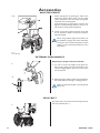
AMPUTEE LEGREST
1-2.
A
B
1. Attach the legrests by pushing the tube at the
upper part of the legrests down into the tubes
on the wheelchair. You must angle the legrests
outwards when inserting them.
Lock the legrests by turning them inwards. The
legrests are automatically locked so there is no
risk of them coming off the wheelchair.
2. Loosen screw (A) to adjust the angle of the pad
and its position in depth. Loosen screws (B) to
adjust the height.
When using amputee legrests the balance of
the wheelchair changes. The risk is reduced by
moving the drive wheels backwards. See the
chapter on drive wheel attachment for more
information.
"
4 mm Allen key
EXTERNAL PUSH HANDLES
Adjusting the height of the push handles
1.
1. To raise or lower the height of the push handles turn the knob and raise the handles to the
required height.Tighten when the correct position is achieved.
2.
2. When hole (A) is visible, just above the attachment,
the handle will be in the right “locking-position”.
A
Make sure the push handles is securely locked
before use.
PELVIC BELT
1.
26
The pelvic belt is mounted on the brackets placed at
the rear of chassis (Pic 1).
INVACARE® SPINx
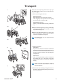
Transport
1.
B
When you are transporting the Invacare® Spinx you
can easily remove certain parts to make the chair
smaller and lighter.
1. Start by removing the armrests.
A
Flip up armrests
Press the button (A), swing up the armrest.
Lift it straight up. You may need to hold it slightly
forward then lift it straight up (B).
Detachable armrests
When you have detachable armrests, just lift them
up.
2a.
B
2a. Remove the fixed legrests by pressing the level (B),
whilst turning the footrests outwards or inwards
and pull them straight up.
2b.Remove the adjustable legrests by pressing the
level (C) backwards, whilst turning the legrests
outwards and pull them straight up.
C
Be careful not to trap your fingers between
frame and legrest.
2b.
3.
Alt. 1
Alt. 2
3. Folding the chair
Q
If you have a backrest bar first detach the left hand
side of the backrest stay by depressing the catch on
the inside of the left hand bracket and then rotate
the stay downwards. Fold the chair by pulling the
seat upwards.
Y
After removing the wheels, flip down the backrest
by grabbing the wire at the lower back of the
backrest and twisting it to release the backrest
locking.
Please be careful when folding the backrest
forward onto the seat as there is a risk of
finger entrapment.
4.
4. Remove the rearwheels by pressing the button in
the centre of the hub whilst pulling the wheel away
from the wheelchair.
INVACARE® SPINx
27
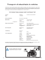
Transport of wheelchairs in vehicles
The Invacare® Spinx has been tested for safety in collisions according to ISO 7176-19. The Invacare® Spinx can be
used for transport in vehicles that have been specially adapted for this purpose. The wheelchair must be securely
fastened in the vehicle according to the methods described on the following page. Remember that the best solution is always to move the user from the wheelchair into a normal car seat.
TEST REPORT FROM DYNAMIC SAFETY RESTRAINT TEST
Test no:
Date:
Pulse specification:
Wheelchair:
=XYX
21/06/2006
?&'
ISO 7176-19 / ISO-10542
>
?&'
?® Spinx
Safety restraint device:
#;;
<<&~">~{~&<<&~*~">~{~&
#
=
&
=&
User safety belt:
#;;
?&~}~">~<
Testdummy:
Hybrid III
<
Test configuration:
< ' ;
&
;<}~;*z
YXY
"
;z
>$XYXX}
Y
QX$}
'heel straps, pelvic belt
The safety restraint devices used in this test must be approved according to ISO10542. We have chosen to work
with Unwin, a well-known quality manufacturer of safety restraint devices for wheelchairs.
Only chairs equipped with transport kit
and pelvic belt (see picture to the right)
are approved for transport in vehicles.
28
INVACARE® SPINx
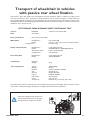
Transport of wheelchair in vehicles
with passive rear wheel fixation
The Invacare® Spinx with passive rear wheel fixation has been tested for safety in collisions according to ISO
7176-19. The Invacare® Spinx with passive rearwheel fixation can be used for transport in vehicles that have
been specially adapted for this purpose. The wheelchair must be securely fastened in the vehicle according to the
methods described on the following page. Remember that the best solution is always to move the user from the
wheelchair into a normal car seat.
TEST REPORT FROM DYNAMIC SAFETY RESTRAINT TEST
Test no:
Date:
Pulse specification:
Wheelchair:
=X}
23/11/2006
?&'
ISO 7176-19 / ISO-10542
?&'
?® Spinx with passive rearwheel fixation
>
Safety restraint device:
#;;
<<&~">~{~&<<&~*~">~{~&
#
=
&
=&
User safety belt:
#;;
?&~}~">~<
Testdummy:
Hybrid III
<
Test configuration:
<
'
;
&
;<zz~;*z
YXX
"
;z
>$XYXX}
Y
QX$}
'
The safety restraint devices used in this test must be approved according to ISO10542. We have chosen to work
with Unwin, a well-known quality manufacturer of safety restraint devices for wheelchairs.
Only chairs equipped with transport kit
and pelvic belt (see picture to the right)
are approved for transport in vehicles.
INVACARE® SPINx
29
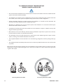
TO OBSERVE BEFORE TRANSPORTING
WHEELCHAIRS IN VEHICLES
<
system of the vehicle whenever feasible.
"
"
;
user manual, section "Test report from dynamic safety restraint test", for test configuration.
$
secured in the vehicle during transit (for example table trays).
without the written consent of Invacare®.
%
diagonal restraint (3-point belt).
'
postural restraints, wheels, etc. (See illustration below.)
"?;QXzY%Y
%
%
system, according to the methods described in this manual.
"
%
lied.
"
as possible.
Please observe that even if these products and recommendations are provided in order to increase security and
safety, injury to vehicle occupants still might occur in the event of a collision or other accidents and no guarantee
is given in this respect.
Correct placement of belt
30
Incorrect placement of belt
INVACARE® SPINx
RESTRAINT METHODS
B
C
A. Front restraints with straps
1. Connect the front straps around the front tube of
the frame, just above the lower polyamid block,
see picture A.
2. Release brakes and tension front straps by pulling
the wheelchair backwards. Re-apply wheelchair
brakes.
B. Rear restraints
1. Attach the snap hooks of the rear straps around
the rear tube of the frame, just above the rear
wheel attachment, see picture B.
2. Tighten the straps.
C. Pelvic belt and 3-point safety belt
1. Check that the pelvic belt is correctly attached
to the wheelchair, adjust the length and fasten it
around the user.
2. Fasten the 3-point safety belt around the user..
A
INVACARE® SPINx
31
Safety instructions/
propelling techniques
We recommend that the qualified person who has prescribed your wheelchair for you, tests the wheelchair and
that he/she makes the adjustments that you want, taking your build and needs into account. We also hope that
you have received help in learning how best to use your chair. Start by practising carefully until you are familiar
+
Moving to and from the wheelchair
Propel the wheelchair as near as possible to the seat that you want to
move to. Apply the brake. Remove/flip up the armrests and detach the
legrests/move them outwards. Do not put any of your weight on the
foot plates, as the chair may tip forwards.
When transfering from the wheelchair do not place your fingers
between frame tube and seat tube.
Stretching and bending
Propel the wheelchair as near as possible. When stretching and bending, do always have full contact between the backrest and the back
otherwise the wheelchair may tip over. Stretching behind the back is
not recommended.
Propelling up a slope
Many experienced users manage to propel up a slope by themselves. In
order not to lose control of the steering and to avoid tipping backwards,
you should always lean forwards whilst propelling up a slope. Propel
the wheelchair forwards using short, quick strokes applied to the hand
rims, in order to maintain speed and steering control.
Generally, help is needed in the case of steep slopes.
If you have to stop on a slope, it is particularly important to ensure that
you do not make any sudden or unexpected backward movements when
you start moving the wheelchair forwards again. As the wheelchair is
already leaning backwards, such a movement can cause the wheelchair
to tip backwards.
Be careful not to trap your fingers between brakepin
and tyre.
Propelling down a slope
We recommend that you get the help of one or more assistants when
going down steep and wet slopes.
First check the slope to see if there are any particular risks, such as
potholes, slippery sections, etc. Never use your brake to slow down.
When you apply the brake on a downward slope, the wheels lock and
the wheelchair can suddenly pull to one side, tip sideways or stop
immediately, which can cause you to be thrown out of the chair. Always
control the speed with the hand rims. Remember that the hand rims may
become hot due to friction, and this may cause injury to your hands. Try
to propel down the slope in a straight line as much as possible. Never
change direction when propelling down a slope. Never propel up or
down a slope crosswise.
32
INVACARE® SPINx
Onto a kerb
This method is for when the assistant is always behind the wheelchair
and creates the greatest safety for the user.
"
Illustration 1
% + securely on the footrests and cannot slide off. Then lean the wheelchair
backwards and push it forwards against the kerb.
Illustration 2
Lower the frontal part of the wheelchair onto the pavement and place
yourself as close to the chair as possible, before you lift up the whole
wheelchair.
Illustration 3
Lean forward and lift/roll the wheelchair over the pavement edge.
Illustration 4
Lower the wheelchair onto the pavement so that the weight is divided on
all four wheels. Ensure that the wheelchair does not roll backwards.
Off a kerb
Follow the procedure above, but in reverse order (step 4, 3, 2 and then
1) to move off a kerb.
Kerbs – alternative method
Generally this method is used by experienced assistants who are stronger
than average. The method can also be used when the kerb or step is
low and only constitutes a minimal obstacle.
The assistant goes backwards onto the pavement and then pulls the
wheelchair up onto the pavement. It is important for the assistant to use
his/her body correctly to prevent injury. Tip the wheelchair backwards
and roll the chair over the kerb onto the pavement. Take particular
care if the kerb is wet or slippery.
Escalators
Do not use the escalator when you are in the wheelchair. Find out
whether there is a lift nearby.
Stairs
We advise you to avoid going up/down stairs in your wheelchair where
possible, and to choose an alternative route instead.
We recommend that you receive help from two assistants to get up and
down stairs. One assistant goes in front of the chair and hold the frame
of the wheelchair, whilst the other assistant goes behind the chair and
holds the push handles. Fold the anti-tip device upwards. Balance the
wheelchair on the drive wheels until the balance point is found. The
wheelchair is then rolled down the stairs, step by step, by letting the
drive wheels roll over the edge of each step. Assistants must remember
not to hold removable armrests or legrests. In addition, assistants should
remember to lift correctly, using their legs and keeping their backs as
straight as possible.
INVACARE® SPINx
33
Guarantee
We provide a two-year guarantee from the delivery date. Damage due to wear
and tear on upholstery, tyres, (rubber) tubes, hand rims and castors etc., is not
covered by the guarantee. Damage that has been caused through physical violence
or abnormal use is not covered. Damage caused by users who weigh more than
125 kg is not covered. The guarantee will only apply if the maintenance instructions are followed.
Maintenance instructions
Your Invacare® Spinx is easy to keep clean and in good condition. Just follow the
instructions below.
Cleaning
<
detergent may be used. If necessary, the upholstery can be washed at 40ºC.
Ordinary washing powder/liquid can be used.
>
K$ XZ gent.
Washing and Disinfection
1. Remove all loose and removable covers and wash these in a washing machine
following the washing instructions for each article.
2. Spray the wheelchair with detergent, for example a car-cleaning agent with wax,
and leave on to work.
3. Rinse the wheelchair with a high-pressure cleaning or ordinary jet of water
depending on how dirty the chair is. Do not aim the jet towards bearings and
draining holes. If the wheelchair is washed in a machine the water must not be
hotter than 60 degrees.
4. Spray the chair with alcohol for disinfection.
5. Leave the chair to dry in a drying cabinet. Remove parts where water has collected for example in end tubes, ferrules etc. If the chair has been washed in a
machine, blow-drying with compressed air is recommended.
Wheels and tyres
<$
=
pumped up using the same type of pump used for cars.
When inflating tyres there is a risk of explosion if over inflated. The recommended pressure is written on the side of the tyre
Technical servicing
?+
be used.
?+"
authorised wheelchair technicians or Invacare's service department once a year.
The address and telephone number are on the back cover of the manual.
?
contact Invacare immediately. The address and telephone number are on the
back cover of this manual.
34
INVACARE® SPINx
Service life
We estimate that Invacare® Spinx has a service life span of five years. It is difficult to
state the exact length of the service life of our products, and the length stated is an
estimated average life span based on normal use.
The life span may be considerably longer if the wheelchair is used to a limited
extent, and if it is used with care, maintained and handled properly. The life span
may be shorter if the wheelchair is subjected to extreme use.
Accidents/Near-accidents
Please inform your Invacare sales company (phone number is on the back cover) of
any accidents/near-accidents that were caused by this wheelchair and that have led to/
could have led to personal injury.
The relevant authority in your country must also be notified.
Testing
Invacare® Spinx has been tested and approved by The Swedish Handicap Institute and
TÜV in Germany and is CE -marked according to the Medical Device Directive.
Recycling
"
=
#
<
=
Chassis
The chassis is produced in aluminium and is fully recyclable. Recycling aluminium requires
Yz
Plastic parts
The plastic parts in the chairs are produced of plastic of the family "Thermoplastic" and
K
@Z"
material is polyamide. This material can be recycled or burned in approved facilities.
Upholstery
Upholstery is produced of polyester, nylon or PVC. The efficient way to recycle the
parts is to burn them in approved facilities.
Wheels, tyres and tubes
"
and can be recycled according to above.
"
Packing
All Invacare Rea AB packing material is developed to fit the products in an optimal way
to reduce unnecessary waste in material. All boxes are recyclable.
Contact your local recycling agent to get correct information how to handle the above
mentioned materials.
Surface treatment
;
@%
lacquered aluminium parts are anodised. Visible wooden parts are lacquered.
INVACARE® SPINx
35
Manufacturer:
Invacare Rea AB
Växjövägen 303 S-343 71 DIÖ SWEDEN
Sales companies:
Sales Units:
Danmark:
Invacare A/S, Sdr. Ringvej 37, DK-2605 Brøndby
Tel: (45) (0)36 90 00 00, Fax: (45) (0)36 90 00 01
[email protected]
Deutschland:
Invacare Aquatec GmbH, Alemannenstraße 10,
D-88316 Isny
Tel: (49) (0)75 62 7 00 0, Fax: (49) (0)75 62 7 00 66
[email protected]
Ulrich Alber GmbH, Vor dem Weissen Stein 21,
D-72461 Albstadt-Tailfingen
Tel: (49) (0)7432 2006 0, Fax: (49) (0)7432 2006 299
[email protected]
European Distributor Organisation:
Invacare, Kleiststraße 49, D-32457 Porta Westfalica
Tel: (49) (0)57 31 754 540, Fax: (49) (0)57 31 754 541
[email protected]
España:
Invacare SA, c/Areny s/n, Polígon Industrial de Celrà,
E-17460 Celrà (Girona)
Tel: (34) (0)972 49 32 00, Fax: (34) (0)972 49 32 20
[email protected]
France:
Invacare Poirier SAS, Route de St Roch, F-37230
Fondettes
Tel: (33) (0)2 47 62 64 66, Fax: (33) (0)2 47 42 12 24
[email protected]
Ireland:
Invacare Ireland Ltd, Unit 5 Seatown Business
Campus, Seatown Road, Swords, County Dublin Ireland
Tel: (353) 1 810 7084, Fax: (353) 1 810 7085
[email protected]
Italia:
Invacare Mecc San s.r.l., Via dei Pini 62, I-36016
Thiene (VI)
Tel: (39) 0445 38 00 59, Fax: (39) 0445 38 00 34
[email protected]
Nederland:
Invacare BV, Celsiusstraat 46, NL-6716 BZ Ede
Tel: (31) (0)318 695 757, Fax: (31) (0)318 695 758
[email protected]
[email protected]
Norge:
Invacare AS, Grensesvingen 9, Postboks 6230,
Etterstad, N-0603 Oslo
Tel: (47) (0)22 57 95 00, Fax: (47) (0)22 57 95 01
[email protected]
[email protected]
Österreich:
Mobitec Mobilitätshilfen GmbH, Herzog Odilostrasse 101, A-5310 Mondsee
Tel: (43) 6232 5535 0, Fax: (43) 6232 5535 4
[email protected], austria@invacare.
com
Portugal:
Invacare Lda, Rua Estrada Velha, 949, P-4465-784
Leça do Balio
Tel: (351) (0)225 1059 46/47, Fax: (351) (0)225
1057 39
[email protected]
Sverige & Suomi:
Invacare AB, Fagerstagatan 9, S-163 91 Spånga
Tel: (46) (0)8 761 70 90, Fax: (46) (0)8 761 81 08
[email protected]
[email protected]
Switzerland:
Mobitec Rehab AG, Benkenstrasse 260, CH-4108
Witterswil
Tel: (41) (0)61 487 70 80, Fax: (41) (0)61 487 70 81
[email protected]
[email protected]
United Kingdom:
Invacare Limited, Pencoed Technology Park, Pencoed, Bridgend CF35 5HZ
Switchboard Tel: (44) (0)1656 776200, Fax: (44)
(0)1656 776201
Customer services Tel: (44) (0)1656 776222, Fax:
(44) (0)1656 776220
[email protected]
Art. No. 1493022-3 2011-06-20
Belgium & Luxemburg:
Invacare nv, Autobaan 22, B-8210 Loppem
Tel: (32) (0)50 83 10 10, Fax: (32) (0)50 83 10 11
[email protected]


![Deep Time User Manual ver.1.3 [ENG]](http://vs1.manualzilla.com/store/data/005775250_1-8eb61345983a4e3ef84e4b82ef32f1cf-150x150.png)