1
F.2. FORCED-AIR CONVECTION
227
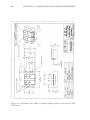
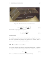
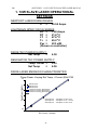
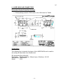
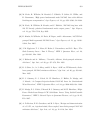
Figure F.1: Heatsink dimensions, measured in metres.
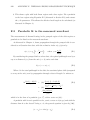
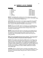
hf
μ
¶¸
24
1=68I 3
1 exp
,
=
24
1=68I 3
(F.4)
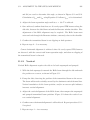
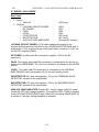
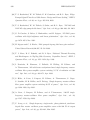
where F is the n spacing parameter, given by
μ
I = 100=7Vi
W
Oi
¶1@4
(F.5)
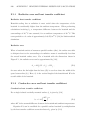
Conductive area
The conductive area of the heatsink is calculated by determining the total surface
area of the heatsink ns and spacings, while the at, back mounting surface is
excluded since it does not see the ambient conditions.
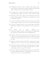
F.2
Forced-air convection
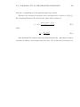
When cooling a heatsink using forced-air convection, radiation is not a signicant
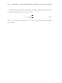
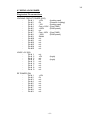
heat dissipation method. Therefore, Equation F.1 can be simplied and written as
vd =
1
kf Df
where Af is calculated as for natural convection (Section F.1.2).
(F.6)