1
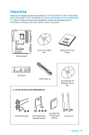
Pepwave Device Connector User Manual Table of Contents 1. Getting Started .................................................................................................................................................4 What’s in the Box .................................................................................................................................................5 Get to Know Your Device Connector............................................................................................................6 Device Connector ............................................................................................................................................6 Device Connector 300M ...............................................................................................................................6 Device Connector IP55/600M IP55 ........................................................................................................6 Device Connector IP67/300M IP67 ........................................................................................................7 Device Connector 600M IP67 ....................................................................................................................7 Access the Web Admin Interface ...................................................................................................................8 Connect by Ethernet ......................................................................................................................................8 Connect by Wi-Fi .............................................................................................................................................8 Choose Your Connection Mode ......................................................................................................................9 Wi-Fi Mode.........................................................................................................................................................9 Wired Mode .......................................................................................................................................................9 2. Basic Setup ...................................................................................................................................................... 10 Basic Setup........................................................................................................................................................... 11 WAN Mode ...................................................................................................................................................... 12 WAN IP Settings ............................................................................................................................................ 13 Wi-Fi WAN Settings (Wi-Fi Mode Only) ............................................................................................. 14 LAN Interface ................................................................................................................................................. 17 Radio Settings ................................................................................................................................................ 18 Roaming Settings (Wi-Fi Mode Only) .................................................................................................. 19 AP Settings ...................................................................................................................................................... 19 3. Advanced Settings........................................................................................................................................ 22 Advanced AP Settings...................................................................................................................................... 23 Keep AP Mode (Wi-Fi Mode Only) ........................................................................................................ 23 AP Transmit Power Adjustment ............................................................................................................ 24 Primary/Secondary/Tertiary AP Settings ......................................................................................... 24 Profile Settings (Wi-Fi Mode Only)............................................................................................................ 25 PepVPN Settings ................................................................................................................................................ 27 Web Administration Settings ....................................................................................................................... 28 Web Access Settings.................................................................................................................................... 29 Web Access Protection .............................................................................................................................. 29 4. Troubleshooting and Maintenance ....................................................................................................... 30 Checking Device Status ................................................................................................................................... 31 Scanned AP (Wi-Fi Mode Only) .............................................................................................................. 31 WAN Connection .......................................................................................................................................... 33 PepVPN............................................................................................................................................................. 33 Ethernet ........................................................................................................................................................... 34 Client ................................................................................................................................................................. 34 Checking and Updating the Firmware Version..................................................................................... 35 Checking for Firmware Updates Online.............................................................................................. 35 Manually Uploading Firmware Updates ............................................................................................. 35 Enabling SNMP................................................................................................................................................... 35 SNMP Settings................................................................................................................................................ 36 Using the Included Diagnostic Tools......................................................................................................... 37 Enabling Remote Event Logs ....................................................................................................................... 37 Remote Syslog Settings .............................................................................................................................. 38 Turning on Remote Assistance.................................................................................................................... 38 Changing the Device Connector’s Operating Mode............................................................................. 38 Restoring Factory Settings ............................................................................................................................ 39 Rebooting the Device Connector ................................................................................................................ 39 Downloading Configuration and Debug Information ........................................................................ 39 5. Appendix.......................................................................................................................................................... 40 Federal Communication Commission Interference Statement...................................................... 41 IMPORTANT NOTE: FCC Radiation Exposure Statement ................................................................. 41 Taiwan NCC Statement ................................................................................................................................... 41 Copyright .............................................................................................................................................................. 41 Disclaimer ............................................................................................................................................................ 42 1. Getting Started What’s in the Box DCS-GN 12V power supply 2.4GHz 5dBi omni antenna DCS-AGN 12V power supply 2x dual-band 5dBi omni antenna DCS-GN-IP55/DCS-AGN-IP55 12V power supply 12V Pepwave passive PoE DCS-GN-IP67/DCS-AGN-IP67 1x waterproof Ethernet kit DCS-AGN2-IP67 1x console adapter 1x waterproof power connector kit 2x waterproof Ethernet kit Get to Know Your Device Connector Device Connector Device Connector 300M Device Connector IP55/600M IP55 Device Connector IP67/300M IP67 Device Connector 600M IP67 Access the Web Admin Interface There are two ways to access the Web Admin page. Connect by Ethernet To access the Web Admin page by Ethernet, your PC must be in the same subnet as the Device Connector (i.e. 192.168.20.X). Your PC should be set up as follow on the Internet Protocol (TCP/IP) Properties or Network screen: Connect by Wi-Fi Connect to the SSID: PEPWAVE_XXX where XXXX represents the last four digits of your device’s serial number (e.g. 7D6E). Passphrase is the last 8 hexadecimal digits of your device’s LAN MAC address (e.g. DDC3CCC0) Now you are ready to start the first time configuration of the Pepwave Device Connector. On your PC, start a web browser, go to this URL: http://192.168.20.1/ Choose Your Connection Mode The Device Connector supports both Wi-Fi and wired connection modes. Wi-Fi Mode Use Wi-Fi mode to communicate with vending machines, thermostats, surveillance cameras, and other Ethernet-only devices using TruePower Wi-Fi. For information on configuring Wi-Fi mode, see Basic Setup. Wired Mode To use the Device Connector as a Layer 2 wired bridge, ideal for situations where Wi-Fi access is unnecessary or a security risk, choose wired mode. For information on configuring wired mode, see Basic Setup. To change settings in Wi-Fi or wired mode, make sure the appropriate mode is selected on the Dashboard page under Switch WAN Mode, and then click the Settings button on the right side of the page. 2. Basic Setup Basic Setup The Basic Settings page offers a variety of common settings to help you get your Device Connector up and running quickly. To access the Basic Settings page, click the Settings button on the Dashboard (or the Settings link found at the top of all pages besides the Dashboard), and then make sure the Basic Settings button on the right side of the next page is selected. WAN Mode To begin setting up the Device Connector in Wi-Fi mode, first make sure that the Wireless radio button, found under WAN Mode, is selected. To set up the Device Connector in wired mode, first make sure that the Wired radio button, found under WAN Mode, is selected. WAN IP Settings Select one of the available options here to choose the method the Device Connector will use to connect to the WAN. Configure Manually Choose this option when assigning a static IP address to the Device Connector. In addition to specifying a static IP address and subnet mask, enter the IP address of your default gateway and preferred and alternate DNS server (if available). Obtain an IP Address Using DHCP To allow your network’s DHCP server to assign an IP address to the Device Connector, select this option. Obtain an IP Address Using PPPoE Select this option to connect the Device Connector to the network using PPPoE authentication. In addition to entering a user name and password used to access the service, specify a preferred and alternate DNS server (if available). None To administer the Device Connector over the WAN using a LAN IP address, select None. Wi-Fi WAN Settings (Wi-Fi Mode Only) Use the controls in this section to specify the settings the Device Connector will use to connect to the Wi-Fi network. Profile Select Once you’ve set up one or more Wi-Fi WAN connection profiles via the Profile Settings page, use this drop-down menu to select the profile the Device Connector will use to connect with other devices on the network. To add a connection profile, click the button. To mark a profile as a favorite, click the button. Wireless Network Name (SSID) Enter the SSID of the network to which you want to connect the Device Connector. To see a list of available networks, click inside this field. If the network you’re looking for doesn’t appear, click the Refresh link to update the list with the latest network changes. To connect to a displayed network, select it from this list. Authentication Choose the type of authentication used by the wireless network the Device Connector will login to. Available values include Open, Static with WEP Key, 802.1x with Dynamic WEP Key, WPA/WPA2-Enterprise, and WPA/WPA2Personal. If an SSID has been selected in the Wireless Network Name (SSID) field, the appropriate encryption type will be selected automatically. Encryption Key If the network the Device Connector will connect to uses encryption, enter the encryption key here. To toggle key visibility, click the Hide / Show Encryption Key link. Auto Login (Portal) Use this control to enable or disable automatic network login. If you choose to enable this setting, enter the username and password to be used for automatic logins. To toggle password visibility, click the Hide / Show Password link. Management VID To restrict VLAN management to a particular VLAN ID, change the default Management VID from 0 to the appropriate value. To allow management sessions without VLAN ID restrictions, leave Management VID set to the default value. Note that a Management VID value of 0 disables session tagging rather than tagging management sessions with 0. MAC Clone If your WAN allows only a single active Internet connection, enable MAC address cloning using this control. When MAC Clone is enabled, the Device Connector will be assigned the same MAC address used to connect to the Internet, regardless of the Device Connector’s actual MAC address. Connect to Any Open Mode AP When this option is enabled, the Device Connector will scan for unencrypted networks and automatically connect to the one with the strongest signal. Custom MAC Enable this option to assign a custom MAC address to the Device Connector using the Custom MAC Address field. Because enabling this option can cause the Device Connector to lose connectivity, it is recommended for advanced users only. Custom MAC Address If you have enabled Custom MAC, enter the desired MAC address here. Loop Protection Enable loop protection to prevent the Device Connector from connecting to an AP SSID, which could cause a signal loop and disrupt Internet access. Preferred AP To connect the Device Connector to a preferred access point automatically, enter the AP’s MAC address here or click a link appearing below APs with matching SSID to fill the field. To specify a minimum signal strength to attempt a connection, set the desired strength using the Min. Signal Strength field. LAN Interface These settings are used to manage the connection between the Device Connector (public) and the LAN (private, protected) sides of the network. IP Address Here, you can set the the internal, or private, ID used to manage the Device Connector. Leaving this field set to the default value is recommended. Subnet Mask Use the subnet mask to specify how many computers the device will support. Leaving this field set to the default value is recommended. Radio Settings Use the settings in this section to manage the Device Connector’s Wi-Fi radio settings. If you are connecting to a wired or cellular WAN, configure these settings according to your preferred Wi-Fi LAN settings. If you are connecting to a Wi-Fi WAN, choose settings that provide the maximum number of usable networks. Radio Mode Radio mode is set to 802.11ng, which is compatible with 802.11n networks and backward-compatible with 802.11bg networks. Channel Width Use the options here to set channel width for 802.11n bonding. Choosing Auto (20/40 Mhz) allows simultaneous use of both channel widths. If you require standard width channels only, choose 20 Mhz. Country Choose your country from the drop-down menu to match frequencies and output power to values allowed in your area. AP Channel (Wired Mode Only) If you are operating the Device Connector in wired mode, select an AP channel from 1 to 11 using this drop-down menu. Channel Scanning Mode (Wi-Fi Mode Only) Choose the channel scanning mode used by the Device Connector’s radio. To scan all channels, select Full. Otherwise, restrict the range of channels to be scanned using: Selective Single or Ch. 1, 6, & 11 Bit Rate Here, you can specify the bit rate used when sending packets. Unless you have a need to specify a particular rate, allowing the Device Connector to automatically negotiate the rate by selecting Auto from this drop-down menu is highly recommended. Roaming Settings (Wi-Fi Mode Only) The settings in this section determine the way roaming is handled when using the Wi-Fi WAN setting. When roaming is enabled, the Device Connector will periodically scan for a connection with a stronger signal but without disrupting the current connection. This behavior is particularly useful when the Device Connector can choose from multiple APs, as in many hotspots and other large area networks. Most home and home office networks, however, would not benefit from enabling roaming. AP Settings Use the options in this section to manage the local area Wi-Fi network that appliances connected to the Device Connector will connect to. Configure Manually Select this option to manually specify AP SSID, authentication method, and encryption key. To clone these values so that the Wi-Fi WAN acts as a repeater, select Configure Automatically. AP SSID Enter the SSID of the Wi-Fi network to which connected appliances will connect. Authentication Choose the type of authentication used by local area Wi-Fi network. Available values include Open, Static with WEP Key, 802.1x with Dynamic WEP Key, WPA/WPA2-Enterprise, and WPA/WPA2-Personal. Encryption Key If the local area Wi-Fi network uses encryption, enter the encryption key here. To toggle key visibility, click the Hide / Show Encryption Key link. Configure Automatically (Wi-Fi Mode Only) To clone the settings of the Wi-Fi WAN, select Configure Automatically. Disable To disable connections to the local area Wi-Fi network, select this option. Keep AP (Wi-Fi Mode Only) Select Enable to broadcast a Wi-Fi SSID even when no active connection is available. Because disabling this setting will result in having to configure the device via wired Ethernet, enabling this feature is highly recommended. AP Transmit Power Adjustment Select from Low, Medium, High, and Max to control the Wi-Fi AP’s transmit power. Note that changing this setting does not affect the power of the connection to a WiFi WAN. Broadcast SSID When this setting is disabled, clients must be manually configured to connect to the network. Enabling this setting is recommended. Client Isolation Enabling this feature prevents devices connected to the same AP SSID from communicating directly with one another. Enabling Client Isolation improves security, especially when allowing untrusted users to connect to the network. Multicast Enhancement When this setting is enabled, multicast packages are converted to unicast packages, improving multicast traffic performance in most cases. Multicast Rate If you have disabled Multicast Enhancement, the setting here will determine a fixed rate for multicast traffic. Changing this setting is recommended only for advanced users. VLAN ID (Wi-Fi Mode Only) If you are using virtual LANs, assign a VLAN ID here. Once the above settings are correct, click Save to make them active. 3. Advanced Settings Advanced AP Settings The Advanced AP Settings page gives you fine-grained control over primary, secondary, and tertiary AP configuration. To access this page, click the AP Settings link found on the left side of the Settings page. Keep AP Mode (Wi-Fi Mode Only) Select Enable to broadcast a Wi-Fi SSID even when no active connection is available. Because disabling this setting will result in having to configure the device via wired Ethernet, enabling this feature is highly recommended. AP Transmit Power Adjustment Select from Low, Medium, High, and Max to control the Wi-Fi AP’s transmit power. Note that changing this setting does not affect the power of the connection to a WiFi WAN. Primary/Secondary/Tertiary AP Settings Use the options in this section to manage the primary, secondary, and tertiary local area Wi-Fi networks that appliances connected to the Device Connector will connect to. Configure Manually Select this option to manually specify AP SSID, authentication method, and encryption key. To clone these values so that the Wi-Fi WAN acts as a repeater, select Configure Automatically. AP SSID Enter the SSID of the Wi-Fi network to which connected appliances will connect. Authentication Choose the type of authentication used by local area Wi-Fi network. Available values include Open, Static with WEP Key, 802.1x with Dynamic WEP Key, WPA/WPA2-Enterprise, and WPA/WPA2-Personal. Encryption Key If the local area Wi-Fi network uses encryption, enter the encryption key here. To toggle key visibility, click the Hide / Show Encryption Key link. Configure Automatically (Wi-Fi Only) To clone the settings of the Wi-Fi WAN, select Configure Automatically. Disable To disable connections to the local area Wi-Fi network, select this option. Broadcast SSID When this setting is disabled, clients must be manually configured to connect to the network. Enabling this setting is recommended. Client Isolation Enabling this feature prevents devices connected to the same AP SSID from communicating directly with one another. Enabling Client Isolation improves security, especially when allowing untrusted users to connect to the network. Multicast Enhancement When this setting is enabled, multicast packages are converted to unicast packages, improving multicast traffic performance in most cases. Multicast Rate If you have disabled Multicast Enhancement, the setting here will determine a fixed rate for multicast traffic. Changing this setting is recommended only for advanced users. VLAN ID (Wi-Fi Mode Only) If you are using virtual LANs, assign a VLAN ID here. Profile Settings (Wi-Fi Mode Only) On the Profile Settings page, you can create separate AP profiles for easy management of various usage scenarios. To get started, click the Profile Settings link found on the left side of the Settings page. To add a new profile, click the button. Once you’ve created a new, basic profile, click the down arrow next to the profile’s name to begin customizing it. SSID Enter the SSID of the Wi-Fi network to which connected appliances will connect. Authentication Choose the type of authentication used by the wireless network the Device Connector will login to. Available values include Open, Static with WEP Key, 802.1x with Dynamic WEP Key, WPA/WPA2-Enterprise, and WPA/WPA2Personal. Profile Name Enter a new name for the profile or accept the default name. Auto Login (Portal) Use this control to enable or disable automatic network login. If you choose to enable this setting, enter the username and password to be used for automatic logins. To toggle password visibility, click the Hide / Show Password link. Once you’ve correctly set up your AP profile, click Save to store the profile. To delete a profile, click the button. To make a profile a favorite, click . If you’d like to sort the profile list by SSID, authentication type, or profile name, click the up or down arrows next to the appropriate column heading. PepVPN Settings PepVPN allows you to easily establish a secure VPN tunnel over any WAN link. To set up PepVPN for use with the Device Connector, first click the PepVPN button found on the left side of the Settings page. To enable PepVPN, select PepVPN from the Mode drop-down menu found at the top of the PepVPN page. Note that PepVPN can be used only when the Device Connector is in router mode. To set up router mode, see Changing the Device Connector’s Operating Mode. Local ID To allow a peer to identify the Device Connector over PepVPN, enter a Local ID for this connection. Name Enter a name for the PepVPN connection in this field. Encryption Choose either 256-bit AES encryption for all VPN traffic or set encryption to Off. Encrypting VPN traffic is highly recommended. RemoteID To allow the Device Connector to identify a PepVPN peer, enter a Remote ID here. Authentication Select a method for authenticating VPN clients. Available values are By Remote Id Only and Preshared Key. Remote IP Address / Host Name When connecting to remote PepVPN peers using a serial number, enter that number here. Data Port Enter a custom outgoing UDP data port from 1 to 65535 or select Default to use port 4500. When port 4500 is unavailable or the remote peer’s firmware version is 5.3 or lower, the outgoing UDP data port defaults to 32015. Layer 2 Bridging To enable Layer 2 bridging, select Yes, and then select None, Manually, or DHCP from the Tunnel IP Address drop-down menu. If you’re configuring a manual tunnel IP address, enter the details in the IP Address and Subnet Mask fields. Once you’ve correctly set up PepVPN, click Save to store your configuration. Web Administration Settings On the Web Administration page, you can specify how administrators can access Device Connector settings remotely, as well as configure remote access security. To view or change these settings, click the Web Administration link found on the left side of the Settings page. Web Access Settings Web Access Protocol Select standard HTTP or secure HTTPS as the protocol used when accessing the Device Connector. Unless using HTTP is required by your network configuration, HTTPS is recommended. Management Port Enter the port to use for remote management. HTTP to HTTPS Redirection To automatically redirect HTTP remote management session requests to HTTPS, select Enable. Web Access Protection Mode Choose WAN Only to allow remote management via WAN but not via LAN. Choose WAN and LAN to allow remote management from any location. To disable Web access protection, select None (not recommended). Password If remote management access requires a password, enter it here. To toggle password visibility, click the Hide / Show Password link. Note that the username used for all remote management sessions is admin. Once you’ve correctly configured remote management access, click Save to store your settings. 4. Troubleshooting and Maintenance Checking Device Status To see the status of WAN connections, PepVPN sessions, Ethernet connections, and more, click the Status link at the top of any page. Scanned AP (Wi-Fi Mode Only) Click the Scanned AP button found on the left side of the page for details on all APs scanned by the Device Connector. WAN Connection Click the WAN Connection button found on the left side of the page for details on device addresses, packet transmission, and more. PepVPN To review PepVPN uptime, tunnel status, and more, click the PepVPN button found on the left side of the page. Ethernet On the Ethernet page, you can find important details about Ethernet connections, including information on errors and dropped packets. Client To see a list of connected network clients, click the Client button found on the left side of the page. Checking and Updating the Firmware Version Click the Firmware link found at the top of any page for details on the current firmware version, as well as tools that allow you to check for and upload updated firmware. Checking for Firmware Updates Online To check for updated firmware, click the Online firmware check button. If updated firmware is available, you’ll find details in the Status bar located under the Online firmware check button. Manually Uploading Firmware Updates To manually upload a firmware update, select the file by clicking the Choose File button, and then highlighting the file stored on your system. To upload the selected file, click the Upload button. Enabling SNMP The Simple Network Managmement Protocol (SNMP) can be a helpful tool to monitor your Device Connector’s operation and detect conditions that need to be addressed by a network administrator. To begin setting up SNMP for use with your Device Connector, first click the System link found at the top of any page, and then click the SNMP button found on the left side of the System page. Note that enabling SNMP increases system overhead, so it’s best to use this feature only when troubleshooting. SNMP Settings v1, v2, v3 To enable SNMP v1, v2, and/or v3, which offer various levels of network management functionality, check the appropriate box(es). Read only community name (v2 only) To restrict SNMP read permission to a particular group of SNMP devices, enter a case-sensitive name, which acts as a shared password, in the Read only community name field. You can also leave this field blank, which sets a default value of Public. Read and write community name (v2 only) To assign read and write permissions to a particular group of SNMP devices only, enter a case-sensitive name, which acts as a shared password, in the Read and write community name field. You can also leave this field blank, which sets a default value of Public. Read only user (v3 only) To configure read permission for SNMP v3, enter the appropriate user name and passwords for the security protocols in use on your network. Read and write user (v3 only) To configure read permission for SNMP v3, enter the appropriate user name and passwords for the security protocols in use on your network. Using the Included Diagnostic Tools To quickly display network settings and help diagnose network problems, you can access a number of common diagnostic tools without leaving the Device Connector Web Admin Interface. To access these tools, click the Tools link found at the top of any page. Next, enter the appropriate network address in the Destination field, and then click either the Ping, lperf, Traceroute, or Nutttcp button to run the selected diagnostic. Enabling Remote Event Logs To set up remote event logging, first click the System link found at the top of any page, and then click the Event Log button found on the left side of the System page. Note that enabling logging increases system overhead, so it’s best to use this feature only when troubleshooting. Remote Syslog Settings Remote Syslog To turn on remote event logging and begin sending device event logs to a particular remote host, check Enable. Remote Syslog Host Enter the IP address of the remote system to which event logs should be sent. Remote Syslog Port Enter the desired port number to be used by the remote system to receive event logs. Once you’ve correctly configured remote syslog settings, click Save to store them. Turning on Remote Assistance To allow a remote troubleshooter to help set up and manage the Device Connector, enable remote assistance by clicking the Misc link found at the top of any page and then clicking Turn On next to Remote Assistance. Changing the Device Connector’s Operating Mode To toggle between router and bridge mode, click the Misc link found at the top of any page, and then click Switch to Bridge Mode or Switch to Router Mode. Restoring Factory Settings To restore the Device Connector to factory settings, click the Misc link found at the top of any page, and then click Restore and Reboot. Rebooting the Device Connector To reboot the Device Connector and clear its memory contents, click the Misc link found at the top of any page, and then click Reboot. Downloading Configuration and Debug Information To help with troubleshooting, you can download the Device Connector’s configuration files, as well as a debug log. To download these files to your system, click the Misc link found at the top of any page, and then click Download next to Configuration File and/or Debug Information. 5. Appendix Federal Communication Commission Interference Statement This equipment has been tested and found to comply with the limits for a Class B digital device, pursuant to Part 15 of the FCC Rules. These limits are designed to provide reasonable protection against harmful interference in a residential installation. This equipment generates, uses and can radiate radio frequency energy and, if not installed and used in accordance with the instructions, may cause harmful interference to radio communications. However, there is no guarantee that interference will not occur in a particular installation. If this equipment does cause harmful interference to radio or television reception, which can be determined by turning the equipment off and on, the user is encouraged to try to correct the interference by one of the following measures: 1) Reorient or relocate the receiving antenna. 2) Increase the separation between the equipment and receiver. 3) Connect the equipment into an outlet on a circuit different from that to which the receiver is connected. 4) Consult the dealer or an experienced radio/TV technician for help. This device complies with Part 15 of the FCC Rules. Operation is subject to the following two conditions: (1) This device may not cause harmful interference, and (2) this device must accept any interference received, including interference that may cause undesired operation. FCC Caution: Any changes or modifications not expressly approved by the party responsible for compliance could void the user’s authority to operate this equipment. IMPORTANT NOTE: FCC Radiation Exposure Statement This equipment complies with FCC radiation exposure limits set forth for an uncontrolled environment. This equipment should be installed and operated with minimum distance 20cm between the radiator & your body. This transmitter must not be co-located or operating in conjunction with any other antenna or transmitter. Taiwan NCC Statement 經型式認證合格之低功率射頻電機,非經許可,公司、商號或使用者均不得擅自 變更 頻率、加大功率或變更原設計之特性及功能 低功率射頻電機之使用不得影響飛航安全及干擾合法通信;經發現有干擾現象 時,應 改善至無干擾時方得繼續使用。前項合法通信,指依電信法規定作業之無 線電通信。 低功率射頻電機須忍受合法通信或工業、科學及醫療用電波輻射性電 機設備之干 擾。 Copyright Copyright © 2013 Peplink The content of this documentation may not be reproduced in any part or as a whole without the prior written permission of Peplink. Disclaimer Peplink does not assume any liability arising out of the application or use of any products, or software described herein. Neither does it convey any license under its patent right nor the patent rights of others. Peplink further reserves the right to make changes in any products described herein without notice. This documentation is subject to change without notice.