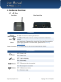
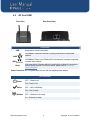
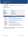
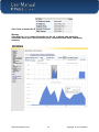
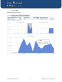
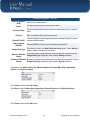
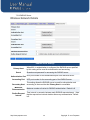
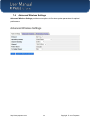
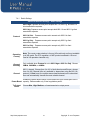
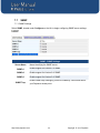
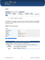
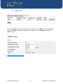
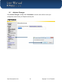
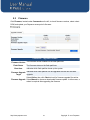
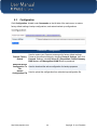
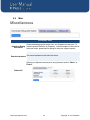
1
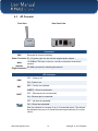
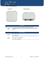
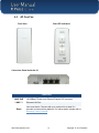
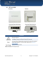
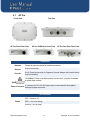
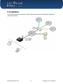
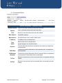
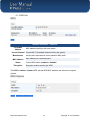
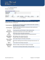
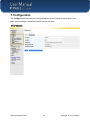
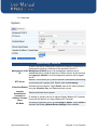
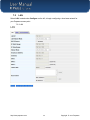
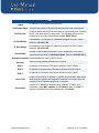
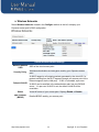
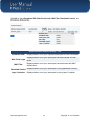
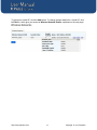
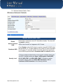
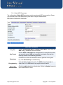
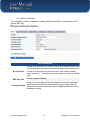
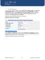
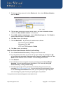
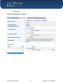
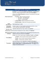
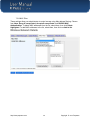
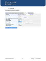
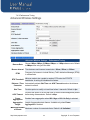
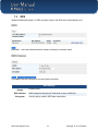
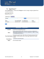
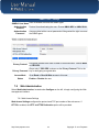
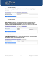
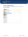
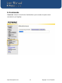
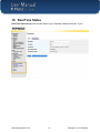
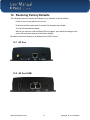
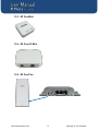
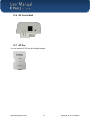
Pepwave AP One Series: AP One / AP One 300M / AP One mini / AP One AC mini / AP One Flex / AP One In-Wall Pepwave AP Pro Series: AP Pro Sept 2014 COPYRIGHT & TRADEMARKS Specifications are subject to change without notice. Copyright © 2014 Pepwave Ltd. All Rights Reserved. Pepwave and the Pepwave logo are trademarks of Pepwave Ltd. Other brands or products mentioned may be trademarks or registered trademarks of their respective owners. User Manual Table of Contents 1. Introduction and Scope .....................................................................................................4 2. Product Features and Benefits .........................................................................................5 3. Package Contents.............................................................................................................6 3.1 AP One ............................................................................................................................6 3.2 AP One 300M ..................................................................................................................6 3.3 AP One mini ....................................................................................................................6 3.4 AP One AC mini ..............................................................................................................6 3.5 AP One Flex ....................................................................................................................7 3.6 AP One In-Wall................................................................................................................7 3.7 AP Pro .............................................................................................................................7 4. Hardware Overview ............................................................................................................8 4.1 AP One ............................................................................................................................8 4.2 AP One 300M ..................................................................................................................9 4.3 AP One mini ..................................................................................................................10 4.4 AP One AC mini ............................................................................................................11 4.5 AP One Flex...................................................................................................................12 4.6 AP One In-Wall..............................................................................................................14 4.7 AP Pro ...........................................................................................................................15 5. 5.1 6. 6.1 7. Installation ........................................................................................................................16 Installation Procedures ................................................................................................17 Information .......................................................................................................................18 System ..........................................................................................................................19 Configuration ...................................................................................................................26 7.1 System ..........................................................................................................................27 7.2 LAN................................................................................................................................32 7.3 Wireless Networks .......................................................................................................35 7.4 Advanced Wireless Settings ........................................................................................50 7.5 WDS...............................................................................................................................54 7.6 SpeedFusion™ .............................................................................................................55 7.7 SNMP .............................................................................................................................59 http://www.pepwave.com 2 Copyright © 2014 Pepwave User Manual 7.8 Web Administration......................................................................................................62 8. Tools - Diagnostic Tools .................................................................................................64 9. Commands .......................................................................................................................65 9.1 Activate Changes .........................................................................................................66 9.2 Firmware .......................................................................................................................67 9.3 Configuration ................................................................................................................68 9.4 Misc ...............................................................................................................................69 10. Real Time Status ...........................................................................................................70 11. Peplink Balance AP Controller ....................................................................................71 12. Restoring Factory Defaults ..........................................................................................72 12.1 AP One ........................................................................................................................72 12.2 AP One 300M ..............................................................................................................72 12.3 AP One Mini.................................................................................................................73 12.4 AP One AC Mini ..........................................................................................................73 12.5 AP One Flex.................................................................................................................73 12.6 AP One In-Wall ...........................................................................................................74 12.7 AP Pro .........................................................................................................................74 13. Appendix .......................................................................................................................75 http://www.pepwave.com 3 Copyright © 2014 Pepwave User Manual 1. Introduction and Scope Pepwave’s AP Series of enterprise-grade 802.11b/g/n Wi-Fi access points is engineered to provide fast, dependable, and flexible operation in a variety of environments, all controlled by an easy-to-use centralized management system. From the small but powerful AP One mini to the top-of-the-line AP Pro, the Pepwave AP Series offers wireless networking solutions to suit any business need, and every Pepwave access point is loaded with essential features such as multiple SSIDs, VLAN, WDS, and Guest Protect. A single Pepwave access point can masquerade as up to four virtual access points, each with its own security policy (WPA, WPA2, etc.) and authentication mechanism (802.1x, open, captive portal, etc.), allowing faster, easier, and more cost-effective network builds. Each member of the Pepwave AP Series family also features a high-powered Wi-Fi transmitter that greatly enhances coverage and performance while reducing equipment costs and maintenance. http://www.pepwave.com 4 Copyright © 2014 Pepwave User Manual 2. Product Features and Benefits Key features and benefits of the Pepwave AP series: High-powered Wi-Fi transmitter enhances coverage and lowers cost of ownership. Independent security policies and encryption mechanisms for each virtual access point allow fast, flexible, cost-effective network builds. Centralized management via InControl reduces maintenance expense and time. WDS support allows secure and fast network expansion. Guest Protect support guards sensitive business data and sub-networks. WMM (Wi-Fi Multimedia) and QoS (Quality of Service) support keeps video and other bandwidth-intensive data flowing fast and lag-free. http://www.pepwave.com 5 Copyright © 2014 Pepwave User Manual 3. Package Contents 3.1 AP One Each Pepwave AP One package contains: 1 x Pepwave AP One 1 x omni-directional antenna 1 x power supply 1 x instruction sheet 3.2 AP One 300M Each Pepwave AP One 300M package contains: 1 x Pepwave AP One 300M 2 x omni-directional antennas 1 x power supply 1 x instruction sheet 3.3 AP One mini Each Pepwave AP One mini package contains: 1 x Pepwave AP One mini 1 x omni-directional antenna 1 x power supply 1 x instruction sheet 3.4 AP One AC mini Each Pepwave AP One AC mini package contains: 1 x Pepwave AP One AC mini 1 x power supply 1 x instruction sheet http://www.pepwave.com 6 Copyright © 2014 Pepwave User Manual 3.5 AP One Flex Each Pepwave AP One Flex package contains: 1 x Pepwave AP One Flex 1 x instruction sheet 3.6 AP One In-Wall Each Pepwave AP One In-Wall package contains: 1 x Pepwave AP One In-Wall 1 x mounting kit 1 x instruction sheet 3.7 AP Pro Each Pepwave AP Pro package contains: 1 x Pepwave AP Pro 1 x instruction sheet 1 x installation guide http://www.pepwave.com 7 Copyright © 2014 Pepwave User Manual 4. Hardware Overview 4.1 AP One Front View Rear Panel View Connectors Antenna RP-SMA connector for attaching the antenna. (Left Connector) WAN Reset 10/100BaseT Ethernet connector, normally connected to a back haul network. Inset reset button. Depress with a pin and hold for at least five seconds to restore factory defaults. For further details, please refer to Restoring Factory Defaults. Power Connector DC 12V power input for use with the supplied power adapter. LED Indicators OFF– Power is off. Power Status ON – Power is on. OFF – Unit is initializing. ON – Unit is ready. Ethernet OFF – Ethernet port is not connected. ON – Ethernet port is connected. Wireless OFF – Wireless is not ready. On – Wireless is ready. http://www.pepwave.com 8 Copyright © 2014 Pepwave User Manual 4.2 AP One 300M Front View Rear Panel View Connectors USB WAN Reserved for future functionality. 10/100BaseT Ethernet connector, normally connected to a back haul network. 10/100BaseT Power over Ethernet 802.3af connector, normally connected to a back haul network. WAN Inset reset button. Depress with a pin and hold for at least five seconds to restore factory defaults. For further details, please refer to Restoring Factory Defaults. Power Connector DC 12V power input for use with the supplied power adapter. Reset LED Indicators Power OFF – Power is off. ON – Power is on. Status OFF – Unit is initializing. ON – Unit is ready. Wireless OFF – Wireless is not ready. On – Wireless is ready. http://www.pepwave.com 9 Copyright © 2014 Pepwave User Manual 4.3 AP One mini Front View Rear Panel View Connectors USB Reserved for future functionality. Power Connector DC 12V power input for use with the supplied power adapter. 10/100BaseT Ethernet connector, normally connected to a back haul WAN network. Antenna RP-SMA connector for attaching the antenna. (Right Connector) LED Indicators PWR OFF – Power is off. ON – Power is on. RDY RED – Device is not booted. AMBER – Device is not booted. ENET OFF – Ethernet port is not connected. ON – Ethernet port is connected. OFF – No client is associated. ON – Clients are associated. Each bar indicates an increase of up to 10 connected clients. The shortest bar indicates from one to 10 clients while the longest indicates 31 or more clients. http://www.pepwave.com 10 Copyright © 2014 Pepwave User Manual 4.4 AP One AC mini Front View Rear Panel View Connectors Power Connector DC 12V power input for use with the supplied power adapter. 100/1000BaseT Ethernet connector, normally connected to a back haul WAN network. LED Indicators Status OFF – Power is off. ON – Power is on. Wi-Fi OFF – Wi-Fi is not connected. ON – Wi-Fi is connected http://www.pepwave.com 11 Copyright © 2014 Pepwave User Manual 4.5 AP One Flex Front View Rear LED Indicators Connectors Panel inside the lid Connectors LAN1*PoE LAN2 / 3 Reset 10/100BaseT Power over Ethernet Passive PoE connector Ethernet LAN Port Inset reset button. Depress with a pin and hold for at least five seconds to restore factory defaults. For further details, please refer to Restoring Factory Defaults. http://www.pepwave.com 12 Copyright © 2014 Pepwave User Manual LED Indicators OFF – Unit is initializing. ON – Unit is ready. OFF – Ethernet port is not connected. LAN ON – Ethernet port is connected. Indicate the signal strength. Mounting the Unit Pepwave AP One Flex can be mounted on a flat surface or a pole using the wall/pole mount (available separately). http://www.pepwave.com 13 Copyright © 2014 Pepwave User Manual 4.6 AP One In-Wall Front View Top View Connectors Panel at the bottom Connectors Panel at the side Connectors LAN POE IN LAN/UPLINK Reset Pass Through Ethernet LAN ports 10/100BaseT Power over Ethernet Passive PoE connector Inset reset button. Depress with a pin and hold for at least five seconds to restore factory defaults. For further details, please refer to Restoring Factory Defaults. Digital pass through for PBX Power Connector DC 48V power input. http://www.pepwave.com 14 Copyright © 2014 Pepwave User Manual 4.7 AP Pro Front View Top View AP Pro Rear Panel View AP Pro 300M Rear Panel View AP Pro Duo Rear Panel View Connectors Antenna Female N-type connectors for attaching antennas. Ground Ground connection. Console RJ-45 Console connector for Pepwave Console Adapter with remote factory reset functionality. WAN Power Connector 10/100BaseT Power over Ethernet 802.3af connector, normally connected to a back haul network. A connector for DC 10V-30V power input, to be used with the supplied waterproof power connector. LED Indicators OFF – Power is off. Status RED – Unit is initializing. GREEN – Unit is ready. http://www.pepwave.com 15 Copyright © 2014 Pepwave User Manual 5. Installation Your Pepwave access point acts as a bridge between wireless and wired Ethernet interfaces. A typical setup follows: http://www.pepwave.com 16 Copyright © 2014 Pepwave User Manual 5.1 Installation Procedures 1. Attach the antenna to your Pepwave access point. 2. Connect the Ethernet port on the unit with the backbone network using an Ethernet cable. The port should auto sense whether the cable is straight-through or crossover. 3. Connect the power adapter to the power connector of the unit. Plug the power adapter into a power source. 4. Wait for the status LED to turn green. 5. Connect a PC to the backbone network. Configure the IP address of the PC to be any IP address between 192.168.0.4 and 192.168.0.254, with a subnet mask of 255.255.255.0. 6. Using Microsoft Internet Explorer 6 or above, Mozilla Firefox 2.0 or above, or Google Chrome 2.0 or above, connect to https://192.168.0.3. 7. Enter the default admin login ID and password, admin and public respectively. After logging in, the following Information main page appears. Click System, located under Configure on the left, to begin setting up your access point. http://www.pepwave.com 17 Copyright © 2014 Pepwave User Manual 6. Information The Information section contains a number of tabs to keep you up-to-date on your access point’s status and operation. http://www.pepwave.com 18 Copyright © 2014 Pepwave User Manual 6.1 System Click System, located under Information on the left, to display tabs for basic and advanced AP configuration options. System Information Model Firmware Version Model name of your access point. Firmware version number running on your access point. AP Name Name of your access point as defined in the configuration. Location Location of your access point as defined in the configuration. Serial Number Serial number of your access point. MAC Address MAC address of your access point. Network IP Information Current gateway IP address of your access point. System Time Current system time with respect to the configured time. Up Time Up time of your access point since the most recent boot. Click the Detail link next to Network IP Information to check IP Address Mode, IP Address, Subnet Mask, Default Gateway, and DNS Server. http://www.pepwave.com 19 Copyright © 2014 Pepwave User Manual Click Close to dismiss the IP Info dialog. Wireless Click Wireless, located under Information on the left, to display tabs containing information about your Pepwave access point, connected clients, WDS, and nearby networks. http://www.pepwave.com 20 Copyright © 2014 Pepwave User Manual 6.1.1 AP Info http://www.pepwave.com 21 Copyright © 2014 Pepwave User Manual Wireless Information – AP Info Wireless Network SSID Radio Security Policy Channel Default VLAN ID MAC Address (BSSID) SSID of your access point. Frequency used by your access point’s radio. Wireless authentication and encryption methods used by your access point. 802.11 channel used by your access point. VLAN ID tagged onto all outgoing packets generated using the current wireless network profile. Detailed BSSIDs for the current wireless network profile. Usage Data Type Data display used in the Wired Network Usage graph. Check Hourly to display usage in 60-minute increments. Wireless Network Usage Wireless network usage displayed using the options selected from the Usage Data Type drop-down menu and the Hourly checkbox. Number of Wireless Number of wireless clients displayed using the options selected from the Usage Data Type drop-down menu and the Hourly checkbox. Clients Click Info to see Web Portal Login, Wireless Network Firewall, MAC Filter, Bandwidth Control, and Layer 2 Isolation. Click Close to dismiss the Info dialog. Click Stat to check Packets Sent, Bytes Sent, Packets Received, and Bytes Received. Click Close to dismiss the Stat dialog. http://www.pepwave.com 22 Copyright © 2014 Pepwave User Manual 6.1.2 Connected Clients Wireless Information – Connected Clients Refresh Interval Refresh Total Interval used when refreshing connected client data. Click to manually refresh connected client data. Number of connected clients since the last refresh. MAC address Client MAC address. Manufacturer AP manufacturer name, based on MAC prefix. IP Address Type Signal IP address of the connected client. Radio mode of the connected client. Duration Signal strength of the connected client. Time the listed client has been connected to the network, as reported at the last refresh. TX/RX Rate Transmit and receive data rates for the connected client, as reported at the last refresh. TX/RX Bytes (Packets) Transmit and receive data volume for the connected client, as reported at the last refresh. Packet data shown in parenthesis. TX Errs Number of transmit errors for the connected client, as reported at the last refresh. RX Errs Number of receive errors for the connected client, as reported at the last refresh. http://www.pepwave.com 23 Copyright © 2014 Pepwave User Manual 6.1.3 WDS Info Wireless Information – WDS Info Local MAC Address MAC address identifying the local system. Current Channel Current 802.11 broadcast channel used by the system. Manufacturer Access point manufacturer name, based on MAC prefix. MAC Address MAC address for connected peers. Status Encryption Current WDS status: enabled or disabled. Encryption method used by the WDS. Click Edit to enable or disable WDS, edit the WDS MAC address, and select an encryption method. http://www.pepwave.com 24 Copyright © 2014 Pepwave User Manual 6.1.4 Nearby Networks Wireless Information – Nearby Networks Displays whether your access point is set to scan and discover nearby Network Discovery access points. How often your access point scans for nearby access points, providing Scanning Interval Network Discovery is Enabled. Scanning Time Group by Manufacturer SSID Security MAC address Channel Signal (RSSI) Last Seen Status Quantity dropdown menu Refresh Channel scan interval used by your access point when searching for nearby access points. Grouping method used for display of nearby access points. Access point manufacturer name, based on MAC prefix. SSID used to refer to the nearby access point. Client authentication method(s) used by the nearby access point. MAC address of the nearby access point. Channel used by the nearby access point. Radio signal strength of the nearby access point. Time stamp indicating when the nearby access point was last seen, if at all. Current status of the nearby access point. Number of nearby access points to display on one page. Click this link to manually refresh nearby access point data. http://www.pepwave.com 25 Copyright © 2014 Pepwave User Manual 7. Configuration The Configure section allows you to set up all aspects of your Pepwave access point, from basic system settings to advanced wireless options and more. http://www.pepwave.com 26 Copyright © 2014 Pepwave User Manual 7.1 System Click System, located under Configure on the left, to display tabs for basic and advanced AP configuration options. 7.1.1 Basic System Settings - Basic AP Name User-specified name assigned to your Pepwave access point. This name can be retrieved via SNMP. Location User-specified name for the location of your access point. This name can be retrieved via SNMP. Timezone Time region used by the system. All choices are based on UTC. Keep Default IP When enabled, this option maintains 192.168.0.3 as your access point’s default IP address. IP Address Mode IP Address Mode options are Automatic and Manual. Automatic: The IP address of your access point is acquired from a DHCP server on the Ethernet segment. Manual: A user-specified IP address is used for your access point. See next page for an example. http://www.pepwave.com 27 Copyright © 2014 Pepwave User Manual IP Address Mode – Manual Unique IP address used by your Pepwave access point to communicate Static IP Address on the Ethernet segment. This IP address is distinct from the admin IP address (192.168.0.3) on the Ethernet segment. Subnet Mask Default Gateway DNS Server Subnet mask used by your access point. Default gateway used by your access point. DNS server address used by your Pepwave access point to resolve host names. IP Address Mode –Advanced This specifies the username required in order to connect via PPPoE to PPPoE Username acquire Internet connectivity. The information is typically determined by and can be obtained from the ISP. This specifies the password required in order to connect via PPPoE to PPPoE Password acquire Internet connectivity. The information is typically determined by and can be obtained from the ISP. PPPoE Service Name This is a PPPoE parameter which is provided by the ISP. Note: Leave this field empty if you are not sure. http://www.pepwave.com 28 Copyright © 2014 Pepwave User Manual 7.1.2 Advanced System Settings - Advanced VLAN ID from which management sessions are allowed. Establishment of management sessions is restricted to the specified VLAN ID. If Management VLAN Management VLAN ID is set to 0, management sessions can be ID established without VLAN ID restrictions. Default value is 0, which means that tagging is disabled, not that management sessions will be tagged with 0. Network Time Protocol (NTP) Server hostname used when synchronizing NTP Server your access point’s system clock. Default value is pool.ntp.org. Automatic reboot schedule. Check Enable, then set the reboot schedule Scheduled Reboot using the Schedule, Day, and Time drop-down menus. Ethernet Ethernet send and receive speed. Speed/Duplex Controller IP IP address or domain name of an optional Peplink Balance AP Controller. Address / Domain Leave this field blank if not using a Balance AP Controller. Name Access point operation mode. Choose Bridge or Router. When Router is AP Mode selected, the following Manual Router Settings will be available: http://www.pepwave.com 29 Copyright © 2014 Pepwave User Manual 7.1.2.1 Manual Router Settings Manual Router Settings are available only when AP Mode in Advanced System Settings is set to Router. When using Router mode, your Pepwave access point can be used as a DHCP server for devices located behind it in the network. Manual Router/DHCP Server Parameters LAN IP DHCP server IP address. LAN Subnet Mask Subnet mask of the DHCP server. DHCP Server Check to enable the DHCP server feature of your Pepwave access point. The following options will be enabled once you have checked and enabled DHCP Server. IP Start Range First address in the range of IP addresses assigned to DHCP clients. IP Stop Range Last address in the range of IP addresses assigned to DHCP clients. Subnet Mask Subnet mask used by DHCP clients. Broadcast Address Broadcast address used by DHCP clients. Gateway Default routing gateway used by DHCP clients. DNS 1 IP address of the primary DNS server offered to DHCP clients. DNS 2 IP address of the secondary DNS server offered to DHCP clients. DNS 3 IP address of the tertiary DNS server offered to DHCP clients. http://www.pepwave.com 30 Copyright © 2014 Pepwave User Manual Lease Time Length of time that an IP address of a DHCP client remains valid. When lease time has expired, the assigned IP address is no longer valid, and renewal of the IP address assignment is required. http://www.pepwave.com 31 Copyright © 2014 Pepwave User Manual 7.2 LAN Select LAN, located under Configure on the left, to begin configuring a local area network for your Pepwave access point. 7.2.1 LAN http://www.pepwave.com 32 Copyright © 2014 Pepwave User Manual LAN LAN IP IP address of your Pepwave access point. LAN Subnet Mask Specifies the number of clients that can connect to your access point. DHCP Server Check to enable the DHCP server feature of your access point. Enabling DHCP is the best option for most users. The following options will be enabled once you have checked and enabled DHCP Server. IP Start Range First address in the range of IP addresses assigned to DHCP clients. Default is 192.168.1.100 IP Stop Range Last address in the range of IP addresses assigned to DHCP clients. Default is 192.168.1.200. Subnet Mask Number of clients that can connect to your access point. This value should match the value in LAN Subnet Mask. Default is 255.255.255.0. Broadcast Address Broadcast address used by DHCP clients. Gateway Default routing gateway used by DHCP clients. DNS 1 IP address of the primary DNS server offered to DHCP clients. DNS 2 IP address of the secondary DNS server offered to DHCP clients. DNS 3 IP address of the tertiary DNS server offered to DHCP clients. Lease Time Length of time that an IP address of a DHCP client remains valid. When lease time has expired, the assigned IP address is no longer valid, and renewal of the IP address assignment is required. Reservation Assigns an IP address to a specific MAC address. To add a new reservation, enter MAC address and IP Address, then click Add. To remove a reservation from the displayed list, click Delete. http://www.pepwave.com 33 Copyright © 2014 Pepwave User Manual 7.2.2 DMZ DMZ DMZ DMZ IP Enable your AP One unit to become a DMZ device. Address used by external users to connect to your IP’s ports. 7.2.3 Port Forward Port Forward Name IP Port Name for your port forwarding rule. IP address to which ports are forwarded. Choose TCP or UDP to forward the selected port or port range using the specified protocol. Select port options from the drop-down menus on the right, then click Apply to make the port forwarding rule active. http://www.pepwave.com 34 Copyright © 2014 Pepwave User Manual 7.3 Wireless Networks Select Wireless Networks, located in the Configure section on the left, to display your Pepwave access point’s SSID configuration. General Wireless Network Settings Wireless Network SSID of the virtual access point. SSID Wireless authentication and encryption used by your Pepwave access Security Policy point. Default VLAN ID Status MAC Address (BSSID) VLAN ID tagged on all outgoing packets generated by the virtual AP (i.e., packets traveling from the Wi-Fi segment through your access point to the Ethernet segment via the LAN port). If 802.1x is enabled, a per-user VLAN ID can be specified in the authentication reply from the RADIUS server. If a per-user VLAN ID is set, the default VLAN ID will be overridden. Virtual AP status of your access point. Displays Enable or Disable. Detailed BSSID used by your access point. http://www.pepwave.com 35 Copyright © 2014 Pepwave User Manual Click Info to check Broadcast SSID, Web Portal Login, MAC Filter, Bandwidth Control, and Layer 2 Isolation. General Wireless Networks Settings – Info Broadcast SSID Displays whether or not your Pepwave access point’s SSID is broadcast. Displays whether or not your access point can be accessed via Web Web Portal Login portal. MAC Filter Displays whether or not your access point controls access with MAC address filters. Bandwidth Control Displays whether or not your access point is using bandwidth controls. Layer 2 Isolation Displays whether or not your access point is using Layer 2 isolation. http://www.pepwave.com 36 Copyright © 2014 Pepwave User Manual To add a new virtual AP, click the Add button. To change network details for a virtual AP, click its Edit link, which give you access to Wireless Network Details, explained on the next page. http://www.pepwave.com 37 Copyright © 2014 Pepwave User Manual 7.3.1 Wireless Network Details - Basic Wireless Network Details - Basic Enable Select Yes to enable the virtual AP. Select No to disable. The virtual AP is enabled by default. Wireless Network SSID of the virtual AP as it appears to Wi-Fi clients. SSID Check Enable to allow Wi-Fi clients to scan the virtual AP’s ESSID. Note that the BSSID (i.e., the MAC address of the virtual AP) cannot be hidden Broadcast SSID from the scan. To associate with the virtual AP, clients must specify the correct ESSID upon association. Broadcast SSID is enabled by default. Security Level Configures wireless authentication and encryption methods used by the virtual AP. Available options are Open - No Encryption, Static WEP, 802.1X, WPA-TKIP, and WPA2-AES:CCMP. For details on setting encryption options, please see Static WEP Parameters, 802.1x Parameters, WPA Parameters in the following sections. http://www.pepwave.com 38 Copyright © 2014 Pepwave User Manual 7.3.1.1 Static WEP Parameters The configuration of Static WEP parameters enables pre-shared WEP key encryption. Please note that static WEP offers weak security and does not support authentication. Static WEP Parameters Key Size Choose 40 bits (64-bit WEP) or 104 bits (128-bit WEP). When using the WDS setting, 128 bits will also be available. Key Format Choose ASCII or HEX.ASCII can be applied only to encryption keys that are manually entered. HEX can be applied to encryption keys that are manually entered or automatically generated. Passphrase Combination of words and characters used to generate an encryption key. Click Generate Key to create the key. Encryption Key User-specified encryption key value. For ASCII format, key length is either 5 or 13. For HEX format, key length is either 10 or 26. Shared Key Authentication Check to enable shared key authentication. Default is disabled, meaning open authentication is used. http://www.pepwave.com 39 Copyright © 2014 Pepwave User Manual 7.3.1.2 802.1X Parameters The configuration of 802.1X parameters enables RADIUS-based 802.1X authentication with a dynamic WEP key. 802.1x Parameters 802.1X Version Choose v1 or v2 of the 802.1x EAPOL. When v1 is selected, both v1 and v2 clients can associate with the access point. When v2 is selected, only v2 clients can associate with the access point. Most modern wireless clients support v2. For stations that do not support v2, select v1. Default is v2. WEP Key Size Choose 40 bits or 104 bits. Re-keying Period Length of time throughout which the broadcast key remains valid. When the re-keying period expires, the broadcast key is no longer valid, and broadcast key renewal is required. Default is 14400 seconds (four hours). 0 disables re-keying. http://www.pepwave.com 40 Copyright © 2014 Pepwave User Manual 7.3.3.3 WPA parameters The configuration of WPA parameters enables WPA-TKIP, WPA2-AES:CCMP, and WPA-TKIP and WPA2-AES:CCMP. To enable WPA and WPA-PSK, configure WPA-TKIP. To enable WPA2 and WPA2-PSK, configure WPA2-AES. When WPA or WPA2 is configured, RADIUSbased 802.1x authentication with TKIP encryption method is enabled. When using this configuration, Pre-Shared Key should be disabled. The security level of this method is known to be very high. When WPA-PSK or WPA2-PSK is configured, a Pre-Shared Key or Passphrase is used for data encryption and authentication. When using this configuration, Pre-Shared Key should be enabled. Key length must be from 8 to 63 characters. The security level of this method is known to be high. http://www.pepwave.com 41 Copyright © 2014 Pepwave User Manual 7.3.4 Web Portal Login Once your Pepwave access point is registered with Pepwave InControl, you can apply configurations, update firmware, and monitor network activity remotely using this centralized management system. For details, see http://www.pepwave.com/products/incontrol/. 7.3.4.1 Tip: How to Set Up a Pepwave AP Guest Portal in InControl To set up a Guest Portal, (1) enable the guest portal function and (2) create guest accounts and set up a portal page. Step One: Enable the Guest Portal 1. Log into InControl with your username and password. <https://incontrol.pepwave.com/> 2. Click the Configuration tab, then locate the desired configuration profile. http://www.pepwave.com 42 Copyright © 2014 Pepwave User Manual 3. To find your wireless network, click the Wireless tab. Next, check Wireless Networks, then click More…. 4. Click the name of the SSID you have set up. Note: If you have not added a wireless network, click New wireless network... to create one. 5. On the Edit a wireless network page, click the Web Portal Login tab. Click Enable to enable Web portal logins. Click OK to continue. 6. Click Save to save your changes. 7. Click the Web Admin tag and setup the web access as follows: Web Access Protocol: HTTPS Management Port: 443 HTTP to HTTPS Redirection: Enable 8. Click Save to save your settings. Step Two: Create Guest Accounts and Set Up a Portal Page 9. Go to Guest Portal and Accounts by clicking on the link on the left. 10. You can generate more than one account at one time. Change the parameters in No. of accounts to be generated, Username prefix, Sequence number suffix, and Time Quota. Default time limit is set to 24 hours. You can change the time limit. 11. Click Generate. 12. You should now have some guest accounts generated as shown Unused Guest Accounts. You can download account information in CSV format by clicking All, Generated today, or Not generated today. 13. A standard portal page will be generated automatically after guest accounts are generated (http://guest.pepwave.com). You can customize the portal page by clicking on the Portal Page Customization tab, where you can upload your logo image and enter a message for guests. Preview your portal page, then publish it. Your guest accounts and portal page are now ready for use. http://www.pepwave.com 43 Copyright © 2014 Pepwave User Manual 7.3.5 Guest Protect http://www.pepwave.com 44 Copyright © 2014 Pepwave User Manual Wireless Network Details - Guest Protect Enables settings to Block all private IPs / Custom Subnet / Block Exception. If you have selected Block all private IPs or Custom Subnet, these IPs / subnets will be blocked no matter what Firewall Mode is selected. When Block Exception is selected, IPs entered will be excluded from the blocking list. Block LAN Access Block SpeedFusion™ Bandwidth Management Upstream Limit Private IP – Blocks common private IPs: o 192.168.0.0 – 192.168.255.255 o 172.16.0.0 – 172.31.255.255 o 10.0.0.0 – 10.255.255.255 Custom Subnet – Blocks user-specified IP subnets. Block Exception – Blocks all IPs except those specified. Block SpeedFusion™ traffic. Enables settings to control upstream and downstream limits. You can control bandwidth usage Per VAP or Per Client. Upstream bandwidth limit in kbps. Default is 0: Unlimited. Downstream Limit Downstream bandwidth limit in kbps. Default is 0: Unlimited. Maximum Number Maximum number of clients that can be simultaneously connected to your Pepwave access point. Default is 0: unlimited. of Clients Enables one of three firewall modes: Lockdown, Flexible, and Disable. Lockdown – Block all traffic except pre-defined exceptions. Firewall Mode Flexible – Allow all traffic except pre-defined exceptions. Disable – Firewall mode is disabled. (Default) Exceptions Specifies exceptions when Lockdown or Flexible Firewall Mode is selected. Exceptions can be added by type, including Port, Domain, IP Address, MAC Address, and Application/Service. Click Apply to save changes and make them active. http://www.pepwave.com 45 Copyright © 2014 Pepwave User Manual 7.3.6 MAC Filter These settings allow your administrator to control access using Mac address filtering. Choose from None, Deny all except listed, Accept all except listed, and RADIUS MAC Authentication. To delete MAC addresses from the list, select them, then click Delete highlighted. To add MAC addresses to the list, select them, then click <<<Add to list. http://www.pepwave.com 46 Copyright © 2014 Pepwave User Manual 7.3.7 Advanced http://www.pepwave.com 47 Copyright © 2014 Pepwave User Manual Wireless Network Details - Advanced Data Rate Choose Fixed or Auto. Fixed forces all data packets to be transmitted using the selected transmit rate. Auto selects the best transmit rate, using the selected transmit rate as the minimum auto transmit rate. The rate options and values chosen here will be affected by selected Protocol and Channel Bonding. Multicast Filter Enables filtering multicast network traffic to the wireless SSID. Multicast Rate Transmit rate used for sending multicast network traffic. The rate value chosen here will be affected by selected Protocol and Channel Bonding. IGMP Snooping (Multicast Enhancement) Enables listening to Internet Group Management Protocol traffic between your Pepwave access point and hosts. Enabling this option ensures that hosts receive multicast traffic only from groups they have joined. DHCP Setting Choose None, Relay, or Server. Choosing Relay or Server will forward DHCP requests to a specified DHCP server and prevent broadcast messages from being propagated on the Ethernet segment. Upon selecting this option, the DHCP server IP address (or DHCP server settings) will be prompted. Default VLAN ID VLAN Pooling VLAN ID to be tagged on all outgoing packets generated from the virtual AP (i.e., packets that travel from the Wi-Fi segment through your Pepwave access point to Ethernet segment via the LAN port). If 802.1x is enabled and a per-user VLAN ID is specified in authentication reply from the Radius server, then the value specified by Default VLAN ID will be overridden. Default value is 0, which means that tagging is disabled, not that management sessions will be tagged with 0. Enables VLAN pooling using the values specified in VLAN Pool. Network Priority (QoS) 802.1p QoS value marked on all outgoing packets generated from the virtual AP (i.e., packets traveling from the Wi-Fi segment through your Pepwave access point to the Ethernet segment via the LAN port). Choose Gold, Silver, or Bronze. Layer 2 Isolation Layer 2 refers to the second layer in the ISO Open System Interconnect model. When this option is enabled, clients on the same VLAN, SSID, or subnet are not allowed to communicate directly via the Layer 2 Protocol(s). Traffic is passed to upper communication layer(s). With this option disabled, clients on the same VLAN communicate with each other directly. (Windows network resources browsing is possible.) Default is disabled. http://www.pepwave.com 48 Copyright © 2014 Pepwave User Manual 7.3.8 RADIUS Server RADIUS Server Settings Primary Host Secret When 802.1x authentication is configured, the RADIUS server specified by this setting will be used for authentication and accounting. Shared secret password for accessing the RADIUS server. Authentication Port UDP port number for the authentication port of the RADIUS server. Accounting Port UDP port number for the accounting port of the RADIUS server. Secondary Host This setting allows the RADIUS server to used for authentication and accounting in the event that the Primary Host is unavailable. Maximum Retransmission Maximum number of retries for RADIUS authentication. Default is 3. Radius Request Interval Time interval, in seconds, between each RADIUS request attempt. Note that the request time interval doubles after every retransmission. Default is 3. http://www.pepwave.com 49 Copyright © 2014 Pepwave User Manual 7.4 Advanced Wireless Settings Advanced Wireless Settings provides more options to fine-tune system parameters for optimal performance. http://www.pepwave.com 50 Copyright © 2014 Pepwave User Manual 7.4.1 Radio Settings Advanced Wireless Settings - Radio Settings 802.11bgn: Pepwave access point accepts 802.11b, 802.11g, and 802.11n client association requests. 802.11b/g: Pepwave access point accepts both 802.11b and 802.11g client association requests. Protocol 802.11b Only: Pepwave access point accepts only 802.11b client association requests. 802.11g Only: Pepwave access point accepts only 802.11g client association requests. 802.11n Only: Pepwave access point accepts only 802.11n client association requests. Operating Country Note: The country code selection is for non-US model only and is not available to all US model. Per FCC regulation, all WiFi product marketed in US must fixed to US operation channels only. Channel Bonding Only available when Protocol is set to 802.11bgn or 802.11n Only. Choose 20MHz, 20/40MHz, or 40MHz. Channel 802.11 channel. Choose from 1 to 11. In North America and Europe, choose from 1 to 13. (Channel 14 is only available in Japan when using the 802.11b protocol.) If Auto is set, the system scans channels based on the scheduled time and automatically chooses the most suitable channel. Enables the power boost feature, which maximizes your access point’s Wi-Fi Power Boost capacity. Please enable only if local regulations permit. Tx Output Power Choose Max, High, Medium, or Low transmission output power. http://www.pepwave.com 51 Copyright © 2014 Pepwave User Manual 7.4.2 Advanced Features Advanced Wireless Settings – Advanced Features Discover Nearby Networks Enables your Pepwave access point to scan and discover nearby networks. Specifies how often your access point goes to other channels to discover Scanning Interval nearby networks. Scanning Time Specifies how long your access point stays on other channels to discover nearby networks. Scheduled Radio Availability Click Add to specify radio availability schedule options. If no options are specified, the radio defaults to On. WMM Enables Wi-Fi Multimedia (WMM), also known as Wireless Multimedia Extensions (WME), on your access point. Default is enabled. http://www.pepwave.com 52 Copyright © 2014 Pepwave User Manual 7.4.3 Performance Tuning Advanced Wireless Settings – Performance Tuning Beacon Rate Choose 1Mbps, 2Mbps, 5.5Mbps, 6Mbps, or 11Mbps beacon rate. Default is 6Mbps when using a 5Ghz radio. Beacon Interval Time between each beacon transmission: 100ms, 250ms, or 500ms. DTIM RTS Threshold Frequency for beacon to include Delivery Traffic Indication Message (DTIM) in milliseconds. Minimum packet size needed to send an RTS using the RTS/CTS handshake. A setting of 0 disables this feature. Distance / Time Automatically adjusts Slot Time and ACK Timeout based on the distance entered in meters. Convertor Slot Time Provides option to modify unit wait time before it transmits. Default is 9μs. ACK Timeout Provides the option to set the wait time to receive acknowledgement packet before doing retransmission. Default is 48μs. Frame Aggregation Enables frame aggregation when 802.11bgn or 802.11n Only is selected. Aggregation Length Length of aggregation data frames. Available only when Frame Aggregation is enabled. Maximum Number Maximum number of connected clients. Default is 0: Unlimited. of Clients http://www.pepwave.com 53 Copyright © 2014 Pepwave User Manual 7.5 WDS Wireless Distributed System, or WDS, provides a way to link APs when wired cabling is not preferable. WDS also extends wireless network coverage for wireless clients. Click Add to add and configure a new WDS peer connection. WDS Settings Enable MAC Address Encryption Enables WDS. MAC address of the other AP with which to form a WDS link. Security policy used for WDS peer connections. http://www.pepwave.com 54 Copyright © 2014 Pepwave User Manual 7.6 SpeedFusion™ Select SpeedFusion™, located under Configure on the left, to begin configuring SpeedFusion connection parameters. SpeedFusion™ - SpeedFusion™ Local ID Name Local ID to be recognized by peers. Name representing this profile. The name can be any combination of alphanumeric characters (0-9, A-Z, a-z), underscore (_), dash (-), and/or non-leading/trailing spaces ( ). Remote peer serial number. Note that your Pepwave access point will Peer Serial Number establish a VPN connection with a remote peer identified with a serial number. Peer Address Status IP address of the remote peer. Peer connection status. http://www.pepwave.com 55 Copyright © 2014 Pepwave User Manual 7.6.1 SpeedFusion™ Settings Click Add to add a new SpeedFusion connection. http://www.pepwave.com 56 Copyright © 2014 Pepwave User Manual SpeedFusion™ - SpeedFusion™ Settings Enable Select Yes to enable this SpeedFusion profile. Name Name representing this profile. The name can be any combination of alphanumeric characters (0-9, A-Z, a-z), underscore (_), dash (-), and/or non-leading/trailing spaces ( ). Encryption Select 256-bit AES to enable encryption or select Off to disable it. Remote ID Name representing the remote peer. The VPN profile will established only if the remote unit’s ID or serial number matches Remote ID. This ensures that connections are made only with authorized remote units. If a remote unit is later replaced, Remote ID must be updated to match the unit’s ID or serial number. Authentication Peer authentication method. Choose from By Remote ID only or Preshared key. Pre-shared Key Optional field which defines the pre-shared key used for this particular VPN connection. The VPN connection's session key will be further protected by the factor of the pre-shared key. The connection will be up only if the pre-shared keys on each side match. When the peer is running firmware 5.0 or 5.1, this setting will be ignored. Remote IP Addresses / Host Names Enter Internet host names and/or the IP addresses of the remote unit in this field. You may enter only one of the remote unit's WAN IP addresses/host names here even if I the remote unit has multiple WAN connections. Note that IP addresses/host names must be separated by a space or a carriage return. When this field is filled, connection to the remote unit will be attempted. If this field is left blank, the corresponding field at the remote unit must be filled. When the state of any WAN connection changes, the WAN IP addresses will be exchanged. Layer 2 Bridging When this check box is unchecked, traffic between local and remote networks will be IP forwarded. To bridge the Ethernet network of an Ethernet port on a local and remote network, select this check box. When this check box is selected, the two networks will become a single LAN, and any broadcast (e.g., ARP requests) or multicast traffic (e.g., Bonjour) will be sent over the VPN. This field specifies the VLAN ID with which the VPN's traffic should be tagged before sending the traffic to the bridge port. If no VLAN tagging is Management VLAN needed, select No VLAN. To define a new VLAN ID, click New... and ID input the VLAN ID. VLAN IDs that are not referenced by any VPN profiles will be removed from the list automatically. Default is No VLAN. http://www.pepwave.com 57 Copyright © 2014 Pepwave User Manual IP Address Mode IP Address Subnet Mask Data Port IP Address Mode options are Automatic and Manual. Automatic: The IP address of your access point is acquired from a DHCP server on the Ethernet segment. Manual: A user-specified IP address is used for your access point. User-specified IP address for use with Manual IP Address Mode, above. Subnet mask used by your access point. This field specifies the outgoing UDP port number for transporting VPN data. If Default is selected, port 4500 will be used by default. Port 32015 will be used if the remote unit's firmware version is prior to 5.4 or the port 4500 is unavailable for use. If Custom is selected, you can input a custom outgoing port number between 1 and 65535. http://www.pepwave.com 58 Copyright © 2014 Pepwave User Manual 7.7 SNMP 7.7.1 SNMP Settings Select SNMP, located under Configure on the left, to begin configuring SNMP server settings. SNMP - SNMP Settings Server Name Name identifying the SNMP server. SNMPv1 Enable support for Version 1 of SNMP. SNMPv2 Enable support for Version 2 of SNMP. SNMPv3 Enable support for Version 3 of SNMP. SNMP Trap Enable SNMP trap messaging, which is initiated by a client and sent to your Pepwave access point. http://www.pepwave.com 59 Copyright © 2014 Pepwave User Manual 7.7.2 SNMPv1 / SNMPv2 Communities Using SNMPv1/v2 communities, access rights can be controlled. Click New to add a new SNMP v1/v2 community, or click Edit to change the settings of an existing community. Click Remove to delete a community. SNMPv1 / SNMPv2 Community - Settings Community Name Password for getting or setting SNMP values. IP Address and IP IP and subnet address that is allowed to access the SNMP server. Mask Choose Read Only or Read & Write. Access Mode Status Enable or Disable this community. http://www.pepwave.com 60 Copyright © 2014 Pepwave User Manual 7.7.3 SNMPv3 Users By adding SNMPv3 users, access rights can be controlled. Click New to add a new SNMPv3 user, or click Edit to change the settings of an existing user. Click Remove to delete an SNMPv3 user. http://www.pepwave.com 61 Copyright © 2014 Pepwave User Manual SNMPv3 User - Settings SNMPv3 User Name User ID allowed to access the SNMP agent. Authentication Protocol Protocol for authenticating the user. Choose HMAC-MD5 or HMAC-SHA. Authentication Password Users provided with a correct password will be granted the right to access the SNMP agent. Privacy Protocol Encryption method to be used in SNMPv3 communication. Choose None or CBC-DES. Shown only if CBC-DES is chosen as the Privacy Protocol. This is the Privacy Password key for decrypting encrypted data. Access Mode Status 7.8 Grant Read or Read & Write access to this user. Enable or Disable this user. Web Administration Select Web Administration, located under Configure on the left, to begin configuring the Web management interface. 7.8.1 Web Access Settings Web Access Settings configures the protocol and TCP port number of the web server. If HTTPS is enabled, the HTTP to HTTPS Redirection option will be provided. http://www.pepwave.com 62 Copyright © 2014 Pepwave User Manual 7.8.2 Admin Username Admin Username configures the administrator username used to access the Web Admin Interface. To change the administrator username, enter a new username in New Admin Username. 7.8.3 Admin Password Admin Password configures the administrator password used to access the Web Admin Interface. To change to the administrator password, enter the new password into New Password and New Password (confirmation). Note that the two entries must match exactly. 7.8.4 Web Administration Disable Web Administration turns off access to Web Admin Interface. After being turned off, the Web Admin Interface can be re-enabled using SNMP. http://www.pepwave.com 63 Copyright © 2014 Pepwave User Manual 8. Tools - Diagnostic Tools This selection provides three useful tools for diagnosing problems on your network: Ping, Traceroute, and Nslookup. http://www.pepwave.com 64 Copyright © 2014 Pepwave User Manual 9. Commands Commands, located on the left side of the Main Menu, puts a number of system control commands at your fingertips. http://www.pepwave.com 65 Copyright © 2014 Pepwave User Manual 9.1 Activate Changes Click Activate Changes, located under Commands on the left, and confirm to save your configuration and activate your Pepwave access point. http://www.pepwave.com 66 Copyright © 2014 Pepwave User Manual 9.2 Firmware Click Firmware, located under Commands on the left, to check firmware versions, select a boot ROM, and update your Pepwave access point’s firmware. Commands – Upgrade Firmware Firmware Version The firmware version loaded into the flash partitions. Flash Status Boot from The firmware status on the flash partitions. Indicates which flash partition boots up the system. Firmware Upgrade Indicates which flash partition will be upgraded with the next firmware upgrade. Target Select Online, then click Check to look for firmware upgrade files online. Firmware Upgrade Select Manual to choose a downloaded firmware update. In either case, a reboot is required after upgrading the firmware. http://www.pepwave.com 67 Copyright © 2014 Pepwave User Manual 9.3 Configuration Click Configuration, located under Commands on the left side of the main menu, to restore factory default settings, backup configurations, and restore backed up configurations. Commands - Configuration Restore Factory Default Used to restore your Pepwave access point’s factory default settings. Preserve the network settings by checking Preserve Settings, then click Proceed. Settings, including Server IP, Subnet Mask, Default Gateway, DNS Server, and Management VLAN ID will be preserved. Download Active Configuration To Used to download the active configuration for backup purposes. File Upload Used to upload the configuration from a backed up configuration file. Configuration File http://www.pepwave.com 68 Copyright © 2014 Pepwave User Manual 9.4 Misc Commands - Misc Download Debug Information Download debugging information from your Pepwave access point. To facilitate prompt resolution by Pepwave technical support in the event of technical issues, please send a debug file with your support request. Remote Assistance Get remote assistance with technical issues. Reboot your Pepwave access point using firmware saved in Flash 1 or Flash 2. Reboot AP http://www.pepwave.com 69 Copyright © 2014 Pepwave User Manual 10. Real Time Status Real Time Status displays the current status of your Pepwave acess point device. If your access point is managed by a Peplink Balance, the default access of the Balance will be shown. http://www.pepwave.com 70 Copyright © 2014 Pepwave User Manual 11. Peplink Balance AP Controller Since firmware 3.0.6, Pepwave access points can be managed and configured using a Peplink Balance. For details, including the Captive Portal configuration or how Peplink Balance works as an AP Controller, please refer to the Peplink website, FAQs, and Peplink Balance User Manual. http://www.pepwave.com 71 Copyright © 2014 Pepwave User Manual 12. Restoring Factory Defaults The following procedure restores the settings of your Pepwave to factory defaults: Power on the unit and wait for one minute. Press and hold the reset button for at least five seconds, then release. The unit will automatically reboot. Wait for one minute or until the Status LED turns green, upon which the settings of the device will have been restored to the factory defaults. By default, the unit will acquire an IP address from a DHCP server. 12.1 AP One 12.2 AP One 300M http://www.pepwave.com 72 Copyright © 2014 Pepwave User Manual 12.3 AP One Mini 12.4 AP One AC Mini 12.5 AP One Flex http://www.pepwave.com 73 Copyright © 2014 Pepwave User Manual 12.6 AP One In-Wall 12.7 AP Pro You can restore AP Pro via the Console Adapter. http://www.pepwave.com 74 Copyright © 2014 Pepwave User Manual 13. Appendix Federal Communication Commission Interference Statement This equipment has been tested and found to comply with the limits for a Class A digital device, pursuant to Part 15 of the FCC Rules. These limits are designed to provide reasonable protection against harmful interference in a residential installation. This equipment generates, uses and can radiate radio frequency energy and, if not installed and used in accordance with the instructions, may cause harmful interference to radio communications. However, there is no guarantee that interference will not occur in a particular installation. If this equipment does cause harmful interference to radio or television reception, which can be determined by turning the equipment off and on, the user is encouraged to try to correct the interference by one of the following measures: 1) Reorient or relocate the receiving antenna. 2) Increase the separation between the equipment and receiver. 3) Connect the equipment into an outlet on a circuit different from that to which the receiver is connected. 4) Consult the dealer or an experienced radio/TV technician for help. This device complies with Part 15 of the FCC Rules. Operation is subject to the following two conditions: (1) This device may not cause harmful interference, and (2) this device must accept any interference received, including interference that may cause undesired operation. FCC Caution: Any changes or modifications not expressly approved by the party responsible for compliance could void the user's authority to operate this equipment. IEEE 802.11b or 802.11g operation of this product in the U.S.A. is firmware-limited to channels 1 through 11. IMPORTANT NOTE FCC Radiation Exposure Statement This equipment complies with FCC radiation exposure limits set forth for an uncontrolled environment. This equipment should be installed and operated with minimum distance 20cm between the radiator & your body. This transmitter must not be co-located or operating in conjunction with any other antenna or transmitter. The availability of some specific channels and/or operational frequency bands are country dependent and are firmware programmed at the factory to match the intended destination. http://www.pepwave.com 75 Copyright © 2014 Pepwave www.pepwave.com Contact Us: Address: Sales Hong Kong Office A5, 5/F, HK Spinners Industrial Building Phase 6 481 Castle Peak Road Cheung Sha Wan, Kowloon Hong Kong http://www.pepwave.com/contact/sales/ Support http://www.pepwave.com/contact/ Business Development and Partnerships http://www.pepwave.com/partners/channelpartner-program/ Tel: +852 2990 7600


![Pepwave APシリーズ 取扱説明書[第4版]](http://vs1.manualzilla.com/store/data/006695739_3-260f6ffb399071dcdcaa28aa3bab2a76-150x150.png)