1
Axial Loading & Off-Axis Loading
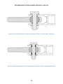
Differentiation exists between the recommended axial load and off-axis load. Please
consider and understand the following definitions:
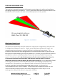
Axial Loading:
A force which acts parallel to and along the cylindrical axis of the rack.
Off-Axis Loading (OAL):
Any components of the loads applied to the rack not
parallel to the rack axis.
In order to determine the OAL the tie-rod load is separated into two components based
on the angle between the tie-rod and rack axis. Note that the methods below assume
that the rack axis is perpendicular to the vehicle longitudinal centerline and parallel to
the ground plane. The loading on the rack must also be considered as the net sum of
the two tie-rod loads. Consider that the maximum pinion tooth loading occurs when
tie-rod forces are acting in the same direction, whereas significant axial rack loading still
occurs when they are acting in opposite directions (such as under hard braking). It is
also recommended to operate the rack under the minimum possible off-axis conditions;
as off-axis loading has detrimental effects to the rack and pinion tooth mesh, rack
bearing loads and friction, and out-of-plane mounting bulkhead loading. In extreme
cases, off-axis loading will result in decreased service life, increased steering effort
requirements, and a larger overall turning circle radius than what might otherwise be
possible.
The calculations presented here are simplified and for reference only. It is
recommended that final design calculations be based on vector representations for all
forces and moments and be conducted throughout the full spectrum of the suspension
and steering travel under all driving conditions.
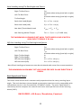
Tie-Rod Angle using Vertical and Longitudinal Offsets
Point 1: Steering Clevis Node
Point 2: Steering Arm Node
Tie-Rod Length:
Vertical Offset :
Longitudinal Offset:
(X1, Y1, Z1)
(X2, Y2, Z2)
TRL
∆Z = Z2 – Z1
∆X = X2 – X1
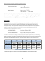
Tie-Rod Angle
𝛼 = sin−1 (
√∆𝑋 2 + ∆𝑍2
𝑇𝑅𝐿
)
*Note that it is recommended to work in degrees!
THE MAXIMUM ALLOWABLE TIE-ROD ANGLE IS 10°… 0±5° IS RECOMMENDED.
10