1
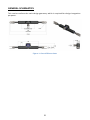
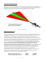
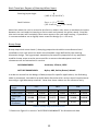
262 MK1
TABLE OF CONTENTS
LIST OF FIGURES AND TABLES .................................................................. 2
INTRODUCTION & ACKNOWLEDGEMENTS.............................................. 4
TERMS AND CONDITIONS OF SALE ........................................................... 5
SPECIFICATIONS ........................................................................................ 7
GENERAL SCHEMATICS ............................................................................. 8
DESIGN INFORMATION ............................................................................ 9
Maximum Rated Load ........................................................................... 9
Axial Loading & Off-Axis Loading ...................................................... 10
Tie-Rod Angle using Vertical and Longitudinal Offsets ................... 10
Axial Loading using Tie-Rod Angle and Forces ................................ 11
Off-Axis Loading using Tie-Rod angle and forces ............................ 11
Rack Speed and Travel ........................................................................ 11
Rack Travel per Degree of Steering Wheel Input ............................ 12
Bump Stops ..................................................................................... 12
Clevis Connection to Tie-Rods ............................................................ 13
ASSEMBLY DIAGRAM ............................................................................. 15
INSTALLATION & OPERATION ................................................................ 17
Mounting Blocks.................................................................................. 17
Hardware ............................................................................................ 17
Lubrication .......................................................................................... 18
Input Shaft Integration........................................................................ 18
Additional Notes.................................................................................. 19
ACCESSORY DRAWINGS ......................................................................... 21
1
LIST OF FIGURES AND TABLES
Table 1: Specifications ....................................................................................................... 7
Table 2: Bump Stop Characteristics ................................................................................. 12
Table 3: Parts List ............................................................................................................. 15
Figure 1: Overall Dimensions ............................................................................................. 8
Figure 2: Installation .......................................................................................................... 9
Figure 3: Recommended Tie-Rod Connection to Clevis, Full Size Bolt (Section) .............. 14
Figure 4: Recommended Tie-Rod Connection to Clevis, Undersized Bolt (Section) ........ 14
Figure 5: zRack 262 Assembly View ................................................................................. 15
Figure 6: Housing Retaining Screws ................................................................................. 16
Figure 7: Safety Wire ....................................................................................................... 18
Figure 9: Bump Stops ....................................................................................................... 21
Figure 10: Upper Mounting Block .................................................................................... 22
Figure 11: Lower Mounting Block .................................................................................... 22
2
LIST OF SYMBOLS AND ACRONYMS
RS
Rack Speed – Linear travel per degree of wheel input
LtL
Lock to Lock – Distance rack travels from full left to full right.
CtC
Center to Center – The distance between two axes.
OAL
Off-Axis-Loading – Any force not parallel to the rack axis
TRL
Tie-Rod Length
SRack
Rack Displacement from Center
β
Steering Wheel Angle from Center
FTR
Tie-Rod Load
Fx
Rack Off-Axis Load Component
Fy
Rack Axial Load Component
3
INTRODUCTION & ACKNOWLEDGEMENTS
Thank you and congratulations on your decision to include zRack technology in your
vehicle project. This product has been engineered to meet the strictest class
requirements for its size and as such should serve its purpose well for many seasons to
come. In order to obtain the best possible performance and longevity from your zRack
please consider and implement the guidelines and recommendations presented in this
document carefully.
zRack was envisioned and created by a small group of dedicated engineers with
extensive FSAE histories and experiences. From the onset, it has always been apparent
to us that many of the products which small race teams use are not particularly suited
towards their requirements, but rather are simply all that is available. We hope that by
filling this special niche the issue will never again be a matter of compromise, and we
will do our utmost to keep the product on the cutting edge of technology and
optimization.
In addition to an advanced product, we offer our combined experience and expertise in
the field of steering and vehicle dynamics and kinematics to assist individuals and teams
execute the installation and utilization of it with a focus on safety and integrity. Should
you have any questions or concerns about the product which are not explicitly or
satisfactorily addressed in this document please do not hesitate to contact us
immediately.
We would also like to acknowledge and thank the many individuals who have
contributed their valuable feedback and experience with the product, and also those
teams who showed the interest and trust in us to implement and test the product in its
early stages. We welcome any and all feedback which is available, so if you have any
comments about your experience or opinions of the product please share them with us,
your feedback is greatly appreciated!
Thank you again, and we wish you all success in your driving endeavors!
Sincerely,
The zRack Team
4
TERMS AND CONDITIONS OF SALE
OPENING THIS PACKAGE INDICATES YOUR AGREEMENT TO BE BOUND BY THE FOLLOWING
TERMS AND CONDITIONS OF SALE
SHOULD YOU NOT AGREE WITH ANY PORTION OF THIS AGREEMENT, RETURN THE PRODUCT
UNUSED IN ITS ORIGINAL PACKAGING ACCORDING TO INSTRUCTIONS IN SECTION 7
1. Orders. All orders are subject to final acceptance by ZEDARO at its principal place of business in Ontario, Canada.
ZEDARO reserves the right to cancel any uncompleted order or to suspend delivery in the event Buyer (1) becomes
insolvent, files for or is the subject of any bankruptcy action, or has a receiver appointed for it; or (2) breaches any
term of this agreement
2. Delivery and Title. Unless otherwise noted, all goods shall be delivered F.O.B. ZEDARO’s Ontario offices and risk
of loss or damage shall pass to Buyer upon ZEDARO’s delivery of goods to shipper or carrier for delivery. Buyer is
responsible for all shipping, handling and insurance charges. Unless Buyer specifically requests a method of
shipment, ZEDARO shall exercise its reasonable discretion in selecting a carrier. If Buyer requests delivery via an
insured and express courier such as Federal Express, Airborne or DHL, where possible, Buyer can provide ZEDARO
with its account number with such courier to facilitate shipment. Times quoted for shipment will be from the date
of order confirmation to Buyer. Unless the parties specifically agree to the contrary, time will not be deemed of the
essence in the transaction.
3. Taxes. All applicable taxes, levies or duties (of whatever nature) will be paid by Buyer, or in lieu thereof, the
Buyer shall provide ZEDARO with a tax exemption certificate acceptable to the taxing authorities.
4. Payments. Each shipment shall be considered a separate transaction and payment shall be made accordingly. In
the event of default by Buyer, ZEDARO may decline to make further shipments without in any way affecting its
rights under other orders. Should ZEDARO decide to continue to make shipments despite any default by Buyer, its
action shall not constitute a waiver of such default or in any way offset or limit ZEDARO’s legal remedies for such
default.
5. Limited Warranty.
A. ZEDARO warrants the following with respect to Product manufactured by ZEDARO or bearing the ZEDARO label:
(1) that the Product is free from defects in material and workmanship and when used in accordance with the user
manual supplied with the Product, will operate substantially in accordance with the applicable functional
specifications applicable to the product purchased; and (2) that upon payment in full for the Product, they shall be
rendered free and clear of liens, claims or encumbrances.
B. The above Product warranty shall extend to the original end user purchaser of the Product for a period of twelve
(12) months from the date of shipment. With respect to any products sold but not manufactured by ZEDARO or
bearing the ZEDARO label, ZEDARO will assign to Customer all available manufacturer warranties. The warranty
period for repaired or replaced Products shall be the remainder of the original warranty period for the repaired or
replaced item.
C. ZEDARO's sole liability under this warranty shall be (a) either to repair or to replace, at ZEDARO’s option, the
defective Product component(s) in accordance with ZEDARO’s return and repair procedures, or (b) if after repeated
efforts ZEDARO is unable to resolve the defect by repair or replacement, to refund the purchase price upon return
of the defective item. ZEDARO shall incur no obligation under this warranty if (1) the allegedly defective Product is
returned to ZEDARO more than thirty (30) days after the expiration of the applicable warranty period; (2) if
ZEDARO’s verifiable tests disclose that the alleged defect is not due to defects in material or workmanship; or (3) if,
in ZEDARO’s sole judgment, the Product has been subjected to misuse or neglect, alteration, improper
maintenance or damage due to excessive physical or heat or stress. This Product warranty is void if the serial
number of the Product has been defaced, altered or removed.
5
6. Warranty Limitations and Exclusions.
A. THE WARRANTIES SET FORTH ABOVE FOR THE PRODUCTS PROVIDED HEREUNDER ARE COMPLETE AND ARE IN
LIEU OF, AND CUSTOMER HEREBY WAIVES, ALL OTHER CONDITIONS,
REPRESENTATIONS, AND WARRANTIES, EXPRESS OR IMPLIED BY STATUTE, USAGE, CUSTOM OF THE TRADE OR
OTHERWISE, INCLUDING WITHOUT LIMITATION, THE IMPLIED WARRANTIES OF MERCHANTABILITY AND FITNESS
FOR A PARTICULAR PURPOSE. NOTWITHSTANDING ANY OTHER OR PRIOR STATEMENT, WRITTEN OR ORAL,
ZEDARO MAKES NO OTHER WARRANTIES REGARDING THE QUALITY OF ITS PRODUCT(S) OR THE MATERIALS
COMTEMPLATED HEREUNDER AND ZEDARO EXPRESSLY DISCLAIMS ANY WARRANTIES OF DURABILITY, THAT THE
PRODUCT WILL MEET ALL OF CUSTOMER’S NEEDS OR THAT THE OPERATION OF THE PRODUCTS WILL BE ERROR
FREE.
B. Customer acknowledges and agrees that the Products supplied under this Agreement are intended for test
purposes within the confines of the Formula SAE competition, and are not specifically designed, manufactured or
intended for use or resale in critical applications or hazardous environments requiring fail-safe performance and in
which the failure of Products could lead directly to death, personal injury, or severe physical or environmental
damage (“High Risk Activities”). ZEDARO and its suppliers explicitly disclaim any express or implied warranty of
fitness for any such use and the customer hereby agrees to release and hold ZEDARO harmless from liability
resulting out of or in connection with implementation of these Products in High Risk Activities.
C. LIMITATION OF LIABILITY. ZEDARO’S LIABILITY SHALL BE LIMITED TO THE PRICE PAID BY CUSTOMER FOR THE
GOODS OR TO REPLACEMENT OF THE GOODS, AND CUSOMTER SHALL BE ENTITLTED TO NO OTHER REMEDY,
REGARDLESS OF THE FORM OF THE CLAIM. ZEDARO SHALL NOT BE LIABLE FOR INDIRECT, SPECIAL, INCIDENTAL,
CONSEQUENTIAL OR PUNITIVE DAMAGES ARISING FROM OR RELATING TO THE USE OF OR INABILITY TO USE THE
PRODUCT, WHETHER OR NOT SUCH DAMAGES ARE FORESEEABLE AND WHETHER OR NOT CUSTOMER HAS BEEN
ADVISED OF THE POSSIBILITY OF SUCH DAMAGES, INCLUDING BUT NOT LIMITED TO LOST PROFITS OR REVENUE,
ATTORNEYS' FEES, DAMAGE TO BUSINESS, LOSS OF USE OF EQUIPMENT, DOWN-TIME COSTS OR DAMAGES FOR
DELAY, OR FOR DAMAGES FOR ECONOMIC LOSSES OR PROPERTY DAMAGE ARISING FROM ANY ACTS OR
OMISSIONS, WHETHER IN NEGLIGENCE, STRICT LIABILITY, OR OTHER PRODUCT LIABILITY THEORIES. THE
LIMITATIONS OF LIABILITY AND WARRANTY DISCLAIMERS STATED IN THIS AGREEMENT FORM AN ESSENTIAL BASIS
OF THE BARGAIN BETWEEN THE PARTIES AND APPLY REGARDLESS OF WHETHER ANY LIMITED REMEDY
HEREUNDER FAILS OF ITS ESSENTIAL PURPOSE.
7. Product Repair and Return Procedures. No Product shall be returned without prior authorization from ZEDARO.
Inoperative or malfunctioning Product must be returned by Customer in protective material, securely packaged to
prevent damage in transit with the original proof of purchase, and shipped prepaid to: ZEDARO, 120 Otonabee
Drive, Kitchener, ON, N2C 1L6, Canada - Phone: (519) 725-2554
ZEDARO will return repaired/replaced Product via surface freight to Customer’s location. The cost of expedited
freight, if requested, shall be at Customer's expense. Product found to be operable after testing (i.e. no trouble
found), may be subject to ZEDARO's then-current handling charge. Repairable out-of-warranty Product will be
repaired at ZEDARO’s then-current repair charges upon receipt of the Product and Customer's applicable purchase
order or other written authorization to repair.
8. Entire Agreement; Assignment. This constitutes the entire agreement of the parties and supersedes all prior
written or oral agreements, representations or understandings relating to the subject matter hereof. Buyer will not
assign its order or any interest therein or any rights under this agreement without the prior written consent of
ZEDARO.
9. Force Majeure. Neither party shall be liable for any failure or delay in performance of its obligations under this
agreement where such performance is prevented or delayed by causes beyond its reasonable control, including
without limitation, flood, war, embargo, strike or other labor dispute, riot, acts of God or the intervention of any
government authority.
10. Governing Law; Disputes. The rights and obligations of the parties arising under or in connection with the sale
of ZEDARO product shall be governed by the laws of the Province of Ontario, Canada. In the event of a dispute
relating to ZEDARO product, it is agreed that the parties shall first submit their dispute to mediation pursuant of
the Commercial Mediation Rules of the Canadian Arbitration Association to be held in Ontario, Canada within 30
days from receipt of written notice of a claim or dispute. The parties shall make a good faith attempt to resolve
their dispute through mediation before seeking any other legal remedy. A party’s failure to respond to a request
for mediation or to attend a scheduled mediation shall entitle the other party to seek other legal relief.
6
SPECIFICATIONS
Property
Mass – Assembly Only
Mass – Installed, w/Mounts
0.235 kg
0.273 kg
zRack 262
0.52 lb
0.60 lb
Kinematic Length
Linear Travel Per Degree of Steering Input
262 mm
0.2383 mm
10.315 in
0.00938 in
Max Linear Travel Per Side
Max Rotary Input Per Side
25.1 mm
105.4°
0.988 in
Recommended Lin. Travel Per Side
Recommended Rotary Input Per Side
≤ 25.0 mm
≤ 104.9°
≤ 0.984 in
Max Axial Load Rating
Max Off-Axis Load Rating (Per Side)
Max Steering Torque
6670 N
2280 N
91 Nm
1500 lbf
512 lbf
67 lbf-ft
Recommended Max Axial Load
Recommended Max Off-Axis Load (Per Side)
Recommended Max Steering Torque
1780 N
780 N
24 Nm
400 lbf
175 lbf
18 lbf-ft
Max Allowable Tie Rod Angle
Recommended Tie Rod Angle
10°
0±5°
CG Vertical Location from Rack Axis
CG Lateral Displacement Range
5.950mm (Towards Pinion Axis)
0±11.633mm
Static Friction / Stiction Range
Static Friction Torque Range
8N ± 1N
0.2 Nm± 0.03Nm
Input Shaft Material / Hardness
AISI 4140H / 34 RC
Pitch Mass Moment of Inertia @ CG1
Yaw Mass Moment of Inertia @CG1
Roll Mass Moment of Inertia @CG1
47615 gmm2
1112699 gmm2
1020306 gmm2
Tie-Rod Clevis Cross Drill Diameter
6.363 ± 0.013 mm
0.2505 ± 0.0005 in
Table 1: Specifications
[1] Note: Mass moments of inertia indicated assuming pinion axis is horizontal, with rack
parallel to vehicle pitch axis and ground plane.
7
GENERAL SCHEMATICS
This section outlines the main design geometry which is required for design integration
purposes.
Figure 1: Overall Dimensions
8
DESIGN INFORMATION
This section is intended to provide information pertaining to the preferred installation
and design integration procedures. It is very important that these recommendations are
heeded in order to ensure the safe and reliable operation of the product.
All mounting block bolts are
M6x1, Class 12.9, DIN 912
Figure 2: Installation
Maximum Rated Load
The maximum rated load is the full axial force in tension or compression which the rack
is designed to withstand in service. Under normal driving conditions this load is not
typically experienced except in cases of collision involving the front wheels. The
maximum rated load has been designated as the maximum load that any person could
be expected to hold keeping the steering wheel still. In reality, the typical driver posture
and position make it nearly impossible to exert the maximum load on the steering
system. Furthermore, it is of critical importance for the sake of safety that drivers be
instructed and trained to release their grip from the steering wheel in cases of
imminent collision in order to reduce the risk of serious injury. For the purposes of load
matching the maximum rated load (6670 N) can be used to design related steering
components. Alternately, a more aggressive load rating can be used which better
matches actual driving conditions excluding impact events. In this case it is
recommended to use a load of 1780 N. Please note that components which are not
rated to withstand impact events must also be designed in such a way as to not
endanger the safety of the driver in any mode of failure.
Maximum Rated Axial Load
Recommended Design Axial Load
9
= 6670 N
= 1780 N
(1,500 lbf)
(400 lbf)
Axial Loading & Off-Axis Loading
Differentiation exists between the recommended axial load and off-axis load. Please
consider and understand the following definitions:
Axial Loading:
A force which acts parallel to and along the cylindrical axis of the rack.
Off-Axis Loading (OAL):
Any components of the loads applied to the rack not
parallel to the rack axis.
In order to determine the OAL the tie-rod load is separated into two components based
on the angle between the tie-rod and rack axis. Note that the methods below assume
that the rack axis is perpendicular to the vehicle longitudinal centerline and parallel to
the ground plane. The loading on the rack must also be considered as the net sum of
the two tie-rod loads. Consider that the maximum pinion tooth loading occurs when
tie-rod forces are acting in the same direction, whereas significant axial rack loading still
occurs when they are acting in opposite directions (such as under hard braking). It is
also recommended to operate the rack under the minimum possible off-axis conditions;
as off-axis loading has detrimental effects to the rack and pinion tooth mesh, rack
bearing loads and friction, and out-of-plane mounting bulkhead loading. In extreme
cases, off-axis loading will result in decreased service life, increased steering effort
requirements, and a larger overall turning circle radius than what might otherwise be
possible.
The calculations presented here are simplified and for reference only. It is
recommended that final design calculations be based on vector representations for all
forces and moments and be conducted throughout the full spectrum of the suspension
and steering travel under all driving conditions.
Tie-Rod Angle using Vertical and Longitudinal Offsets
Point 1: Steering Clevis Node
Point 2: Steering Arm Node
Tie-Rod Length:
Vertical Offset :
Longitudinal Offset:
(X1, Y1, Z1)
(X2, Y2, Z2)
TRL
∆Z = Z2 – Z1
∆X = X2 – X1
Tie-Rod Angle
𝛼 = sin−1 (
√∆𝑋 2 + ∆𝑍2
𝑇𝑅𝐿
)
*Note that it is recommended to work in degrees!
THE MAXIMUM ALLOWABLE TIE-ROD ANGLE IS 10°… 0±5° IS RECOMMENDED.
10
Axial Loading using Tie-Rod Angle and Forces
Right Tie-Rod Force
Tie-Rod Angle
Rack Axial Load (Right)
FTR1
(Positive when acting from left to right)
FTR2
(Positive when acting from left to right)
𝛼
𝐹𝑦1 = 𝐹𝑇𝑅1 cos(𝛼)
Rack Axial Load (Left)
𝐹𝑦2 = 𝐹𝑇𝑅2 cos(𝛼)
Net Axial (Tooth Mesh) Load
𝐹𝑦𝑁𝑒𝑡 = 𝐹𝑦1 + 𝐹𝑦2
Net Steering Wheel Torque
𝑇𝑁𝑒𝑡 = 𝐹𝑦𝑁𝑒𝑡 × (13.608 𝑚𝑚)
Left Tie-Rod Force
THE MAXIMUM ALLOWABLE NET AXIAL TOOTH MESH LOAD IS 6670 N
MAX INPUT TORQUE IS 91 Nm.
Off-Axis Loading using Tie-Rod angle and forces
Right Tie-Rod Force
FTR1
(Positive when acting from left to right)
FTR2
(Positive when acting from left to right)
𝛼1
𝛼2
𝐹𝑥1 = 𝐹𝑇𝑅1 sin(𝛼1 )
𝐹𝑥2 = 𝐹𝑇𝑅2 sin(𝛼2 )
Left Tie-Rod Force
Right Tie-Rod Angle
Right Tie-Rod Angle
Off-Axis Load (Right)
Off-Axis Load (Left)
Net off-axis loading and moments must be calculated with vector force representation.
THE MAXIMUM ALLOWABLE OFF-AXIS LOAD PER SIDE IN ANY DIRECTION IS
2280 N.
Rack Speed and Travel
The linear travel of the rack is constant and proportional to the rotary steering input
angle. The ratio has been chosen based on extensive experience to be compatible with
competitive entries in the Formula SAE / STUDENT classes. The term ‘Rack Speed’ is
commonly used to compare the ratio of rack linear travel per full turn of the steering
wheel (360°).
RACK SPEED = 85.8 mm / Revolution, Constant.
11
Rack Travel per Degree of Steering Wheel Input
Steering Input Angle
β
(-105.4° ≤ β ≤ 105.4°)
Rack Position
𝑆𝑅𝑎𝑐𝑘 = β ×
360°
(-25.1 mm ≤ 𝑆𝑅𝑎𝑐𝑘 ≤ 25.1 mm)
85.8 𝑚𝑚
Note that when the rack is moved to the limit on either side, there is mechanical contact
between the rack and the housing to limit travel and protect the pinion teeth. Consider
that such contact will inevitably cause some wear to the rack and housing. If possible it
is recommended to use a slightly lower travel for design (i.e. ≤ 25 mm)
Bump Stops
Bump stops with some elastic / damping properties should be manufactured and
installed to limit rack travel to within the allowable range defined by the steering
kinematic design. The hygroscopic expansion/contraction properties of any polymers
used for bump stops must be accounted for to ensure that adequate travel and
clearances can be maintained in service.
RECOMMENDED:
Urethane, Silicone, PEEK
NOT RECOMMENDED:
Nylon, ABS, Delrin/Acetal, Metals
In order to streamline the design of bump stops for specific applications, the following
table is presented, intended to provide basic dimensions for various travel requirements
assuming a rigid bumpstop material. Note that these values are for reference only.
Lock to Lock
Angle
Total Travel
Travel per
Side
Bump Stop
Thickness
170°
180°
210°
mm
40.375
in
1.5896
mm
42.750
in
1.6831
mm
49.875
in
1.9636
20.188
0.7948
21.375
0.8415
24.938
0.9818
5.020
0.1980
3.833
0.1509
0.270
0.0106
Table 2: Bump Stop Characteristics
* Please see Figure 9 in section “ACCESSORY DRAWINGS” for dimensional data.
12
Clevis Connection to Tie-Rods
Tie-rod clevises which are compatible with standard spherical rod end connectors
ranging in size M4-M6 (#8-¼ in) from have been supplied. The clevis pin bore diameter
is 6.35mm (0.25 in), and in cases where smaller diameter pins or bolts are desired it is
necessary to manufacture spacers with stepped bosses to account for the difference in
size.
Spacers which have stepped bosses should be designed such that the top of the boss
does not extend beyond the outer faces of the clevis; otherwise the clamping force of
the clevis bolt will not be applied equally to the clevis and spacer/rod-end stack. Boss
tolerances should create a transitional fit (H9/n6).
Use high quality fasteners to make the connection between the tie-rod spherical ball
joints and the clevises. It is recommended to use partially threaded fasteners which are
not threaded in the shear zones between the clevis forks, spacers, and the tie-rod ball.
13
RECOMMENDED TIE-ROD CONNECTION BOLTS: AN4-10A
Figure 3: Recommended Tie-Rod Connection to Clevis, Full Size Bolt (Section)
Figure 4: Recommended Tie-Rod Connection to Clevis, Undersized Bolt (Section)
14
ASSEMBLY DIAGRAM
Figure 5: zRack 262 Assembly View
Table 3: Parts List
1 - Front Housing
2 - Rear Housing
3 - Rack
4 - Pinion
5 - Input Shaft
6 - Clevis (2)
7 - 153 End Collet (2)
8 - Scraper (2)
9 - Wear Ring (2)
10 - Pinion Bearing (2)
11 - Input Shaft Retaining Screw
12 - Belleville Washer
13 – Rack Support Saddle
14 – Clevis Retaining Screws (2)
15 – Housing Retaining Screws
ZD0101
ZD0102
ZD0104
ZD0105
ZD0107
ZD0112
ZD0117
ZD0120
ZD0123
6802-2RS (24x15x5)
M4x0.7-10mm DIN 7985-ISR
0.19x0.47x0.04 DIN 137A
ZD0108
M6x1-16mm DIN 912-A2
See Figure 6 DIN 7985-ISR
15
Figure 6: Housing Retaining Screws
16
INSTALLATION & OPERATION
The design was created around a very specific set of specifications and tolerances and
supporting hardware and vehicle integration must abide by ALL specifications listed
below to ensure proper operation.
Mounting Blocks
Mounting Clamps can be purchased directly from Zedaro. A drawing has also been
provided in case customers choose to manufacture their own.
Please see Figure 10 & 11 in section “ACCESSORY DRAWINGS” for dimensional data.
All circled dimensions in the drawings are necessary to adhere to for proper fit and
function.
Hardware
All housing retaining bolts must be installed with low strength LOCTITE® 222MS™
Threadlocker. Clevis Retaining bolt must be installed with medium strength LOCTITE®
242™ Threadlocker. All hardware must also be torqued to the specified torque settings
listed below.
All M3 Screws:
M4 Retaining Screw:
M6 Clevis Screw:
0.85 Nm
7.5 lbf-in
0.9 Nm
8.0 lbf-in
6.7 Nm
60 lbf-in
M6 Clevis retaining screw must be safety wired to prevent loosening of the screw, as
shown in the following diagram:
17
Figure 7: Safety Wire
Lubrication
The assembly is factory lubricated with Mobil 1™ rack lube (Mobilith SHC 1500) and
does not require any routine maintenance. Disassembly should be avoided if possible in
order to ensure proper operation and maximum service life.
Input Shaft Integration
The input shaft (MD0326) may be attached to the steering shaft by various methods:
1)
2)
3)
4)
5)
6)
Pinning
Keying
Splining
Clamping
Bonding
Welding
To weld the input shaft:
1)
It is recommended to use a filler rod which is most compatible with the
steering shaft material.
2)
Install the rack assembly into the chassis.
3)
Assemble the steering column and steering shaft, and slide the steering shaft
over the input shaft to test fitment and alignment.
4)
Once satisfied with the fit, secure the input shaft to the steering shaft by
clamping or taping it in place. Make several witness marks between the input
18
shaft and steering shaft as visual alignment aids.
5)
Remove the steering shaft and input shaft from the vehicle. Double and triple
check your witness mark alignment before tacking.
6)
Tack weld in four quadrants, giving priority to opposing tacks.
7)
Final welding should be done in a single continuous loop with the part being
rotated by machine or assistant, minimizing heat input.
It is also possible to use plug welds as tacks, or even as the final weld.
The weld bead length can be increased by contouring the end of the steering shaft to
have a wave profile.
It is the sole responsibility of the end-user to ensure that the welding design and process
is suitable for any given application.
Additional Notes
The assembly must not be used as a structural frame member.
The component material and coatings cannot be welded, and will be destroyed by the
heat of any welding process. Do not attempt to weld on the assembly or any of the
components other than the input shaft.
Non-marring wrenches are recommended for use on the end caps during
assembly/disassembly. These can be purchased directly from us or our resellers if
needed.
Sealant is not used in the factory assembly of the housing pieces. The end-user may
apply sealant or bonding if desired, keeping in mind the end cap thread dimensions
must not be substantially affected or else the caps will not thread on properly.
If there is any doubt about any aspect of the product or its use, please contact our
support personnel; we are happy to help! Thank you.
19
20
ACCESSORY DRAWINGS
Figure 8: Bump Stops
21
Figure 9: Upper Mounting Block
Figure 10: Lower Mounting Block
22
23
zRack 262 Installation and Operation Guide
(2015.001)
Zedaro, LLC
120 Otonabee Drive, Level 1
Kitchener, ON, N2C 1L6, Canada
www.Zedaro.com
24
25