1
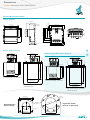
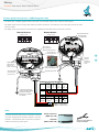
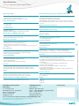
Overview / Installation Mounting Gladiator Microwave Smart Switch Series Overview Correct Mounting Angle Align Sender and Receiver Correct Elevation Rotate so that Visual Alignment Guide is in the same position on both sender and receiver. Maximum Signal Strength to Receiver is indicated by maximum brightness of Green LED on Receiver. Sending Unit Receiving Unit Microwave Beam Incorrect Elevation Sending Unit Receiving Unit > < Installation with Adjustable Mounting Blocked Chute Mounting MAIN PRODUCT FLOW Receiving Unit Sending Unit Position blocked chute detectors to one side of main product flow Mounting with Windowed Weldments Flow/No Flow Metal Bin/Chute Walls MAIN PRODUCT 4” UHMW Windowed Weldment FLOW Sender Receiver Fabricated Bracket 9 Position and aim fabricated brackets to separate structure flowAttach sensors Flow/No Flow Switch if bin/chute walls are subject to high vibration toward main Housing can be rotated within 200º after the mounting thread is tightened, to allow cable entries to face downwards or allow optimal cable clearance.