1
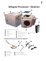
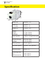
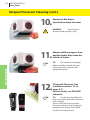
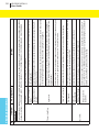
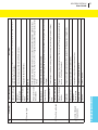
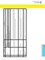
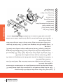
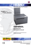
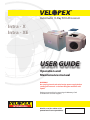
Automatic X-Ray Film Processor Intra - X Intra - XE USER GUIDE Operation and Maintenance manual WARNING: Do not plug into the electrical mains power supply before reading this manual – or before filling the machine with liquids Register your machine by returning the Warranty Card to enable full customer support. Machine serial number to be quoted on all correspondence: ii Introduction Thank you for purchasing your automatic film processor from Velopex - we certainly appreciate your business. In order to maintain the quality of our product and your processing it is important that you pay close attention to the instructions contained in this user manual. This will ensure a long life for your processor. This manual is to be used with the following Velopex processors: Intra-X, Intra-XE. The processor could be dangerous if incorrectly installed or maintained outside the guidelines set out in this manual and the warranty will be voided. This equipment can only be serviced by technically qualified engineer, trained on Velopex machines, and is not designed to be serviced by the end user other than as specified by in this manual. Caution: Use assistance when unpacking and putting the machine in place. Contacts EUROPE MEDIVANCE INSTRUMENTS LTD. Barretts Green Road . Harlesden London . NW10 7AP . UK Tel.: +44 (0)20 8965 2913 Fax: +44 (0)20 8963 1270 USA VELOPEX INTERNATIONAL INC. 105 East 17th Street . St. Cloud Florida . 34769 . USA Tel.: 888 - 835 - 6739 Fax: (407) 957 - 3927 www.velopex.com www.velopexusa.com iii Velopex Processor - Exterior 6 4 3 5 2 7 9 8 10 1 11 8 1 Velopex X-Ray Film Processor - Left Side 2 Film Collector 6 Viewer Cover 3 Endo Slide 7 Daylight Loader viewing Window 4 On/Off Power Switch 8 Hand entry port/Glove 5 ‘Run’ Button 9 Daylight Loader - Left Side 10 Film Entry Guide 11 Transport Module Machine Accessories and Extras Supplied 12 14 16 17 15 13 12 Silicone Grease 13 Film Collecting Tray 14 Cleaning Brush 15 Turning Tool 16 UK - Electricity Supply Cord 17 USA - Electricity Supply Cord 18 Continental - Electricity Supply Cord 18 iv Table of Symbols Symbol Description Alternating Current Off (Power: Disconnect from the mains) On (Power: Connect to the mains) Type ‘b’ equipment ‘RUN’ Button / Process switch Protective Earth (Ground) Symbols used within Manual Tip Attention / Warning 1 Specification ................................................................. 2 Installation* .................................................................. Pre Installation Instructions .............................................. Daylight Loader Installation (when required) ............... Filling with Chemicals ........................................................ 3 3 5 8 INSTALLATION Contents Service Log .................................................................... 24 © October 2005 Medivance Instruments Limited All rights reserved. Issue 6 OM13 I/LIT3601M MAINTENANCE Trouble Shooting .......................................................... 19 TROUBLE SHOOTING Maintenance .................................................................. 15 OPERATION Operation ...................................................................... 11 2 VELOPEX INTRA-X User Guide Specification (H) (D) (W) Width (W) 290mm / 11½” Depth (D) Inc. Loader 435mm / 17” 635mm / 25” Height (H) 315mm / 12½” Weight: Empty Full Tanks 12.1Kg / 26½lb 13.9Kg / 30½lb Tank Capacity 1.4litres / 2½Imp Pints each Standard Supply Voltage 220-240v 50Hz 110-120v 60Hz Warm-up time 10 min. approx. Film Feed Speed 470mm / 18½” per min. Max film width 65mm / 2½” Processing time: Dry Wet-Endodontic 4 min. approx. 2 min. approx. VELOPEX INTRA-X User Guide 3 INSTALLATION Pre Installation Instructions • Unpacking the VELOPEX NOTE: For unpacking and lifting the machine into position it is important to have assistance. The machine comes in a single carton containing: Machine, Operator’s Manual, Silicone Grease, Electrical Cord, Transport Module Turning Tool, Cleaning Brush, Chemical Change Chart and a box of Cleaning Tablets (UK only), and Daylight Loader (as required). 1. Familiarise yourself with the layout of the machine by referring to the images as you progress through the manual. 2. Lift the machine from the carton and position on counter top. Remove outer and inner packaging. The transport modules are protected by internal packing pieces: these must be discarded. 4 VELOPEX INTRA-X User Guide Pre Installation Instructions (cont.) INSTALLATION • Siting of the VELOPEX When using the machine in daylight or a darkroom, avoid sources of intense light. Do not mount the unit under a window, fluorescent light or flood lamp. IMPORTANT NOTE: A well ventilated position is mandatory. The ambient temperature must be below 80oF (27oC). Prevent siting the machine above or near other electrical or mechanical equipment. Surfaces susceptible to water or chemical damage should be avoided, such as carpeted areas. 1. COUNTER a. Use a stable and level counter that will support a weight of at least 100 lbs. (50 Kg.). b. When the machine is filled with chemicals, make sure the stand does not rock or shake. NEVER move the machine with chemicals in the tanks. 2. ELECTRICAL SUPPLY a. 115Vac 60Hz, 10A, 1150W (USA)/230Vac 50Hz, 10A, 1150W (World Wide). b. The power source must be within three (3) feet (1m) of the machine. It should be easily accessible for operation and maintenance. WARNING: X-ray radiation can be harmful to patient, technician and dentist. Inadequate lead shielding of the darkroom or film storage area will also cause fogging from exposure of films to stray x-ray radiation. Consult your local codes, Health Department or Dental Equipment Dealer for proper construction of darkroom or placement of film processing equipment in the vicinity of x-ray radiation sources. VELOPEX INTRA-X User Guide 5 1. Bring the Lid to the upright position. TIP: The Lid can be kept in the upright position while the machine is open, or lifted away. 2. 3a. Remove Side Panel by Sliding it Upwards in its Runners. Remove All Packing / Wrapping Material and Modules. TIP: Start with the Dryer Module, then the Water Module followed by the Fixer and Developer Modules. Those should be removed by sliding the Tanks out. INSTALLATION Daylight Loader Installation (as required) 6 VELOPEX INTRA-X User Guide Daylight Loader Installation (cont.) INSTALLATION 3b. WARNING: When Removing the Fixer and Developer modules, slide tanks sideways until completely clear of the immersion heaters mounted on the machine internal wall. (Retaining Screw X 2) 4. Unscrew the Two Retaining Screws and Remove White protective strip from sealing material on the back of the loader. (Back of Loader) 5. (Front of Loader) Remove Protective Film from Viewing Window Cover. VELOPEX INTRA-X User Guide 7 6. 7. Slide Loader over Film Entry Guide and ‘RUN’ Button, Press the Loader firmly against Machine. Secure Loader with the Two Retaining Screws. INSTALLATION Daylight Loader Installation (cont.) 8 VELOPEX INTRA-X User Guide INSTALLATION Filling with Chemicals 8. Remove Modules (see Installation Sections 1-3b). WARNING: Ensure machine is disconnected from mains power supply whilst filling. NEVER turn on the machine with the tanks empty. 9. Lift the Transport modules from their respective tanks WARNING: BEFORE filling with chemicals run the machine with clean water in the Developer, Fixer and Water tanks with Transport Modules in position – for a complete running cycle to remove all packing debris, dust etc. 10. Fill tanks with their respective chemical solutions or water, Pouring in 1½ quarts (1400ml) of fluid. TIP: Use VELOPEX chemicals designed for your unit. If unobtainable use ONLY another proprietary chemical & always read and follow instructions on bottle. WARNING: DO NOT use Chemistry or Film designed for manual processing. VELOPEX INTRA-X User Guide 9 11. 12. Fill the tanks up to the lowest edge of the Sight Glass. Lower Transport Modules carefully into their respective tanks. Top up - the correct liquid level will show half way up the sight glass. WARNING: This liquid level should be maintained at all times. 13. Grease Immersion Heaters for Developer and Fixer tanks with the lubricant provided. TIP: Spread a thin smear of lubricant over the two projecting metal heating elements. WARNING: grease. Do NOT over INSTALLATION Filling with Chemicals (cont.) 10 VELOPEX INTRA-X User Guide Filling with Chemicals (cont.) INSTALLATION (Drive Pin & Drive Dog) 14. To avoid spillage, carefully return tanks to the machine. Start with the Developer tank followed by the Fixer, Water and finally the Dryer tanks. Engage the module drive pins into the drive dogs, working from right to left. TIP: Slide the Developer and Fixer tanks sideways onto the immersion heaters till backed up fully against the machine internal wall. 15a. Return side panel and lid. WARNING: spilled solution. Wipe dry any 15b. The Machine may now be switched on. TIP: Check that all modules are engaged and running smoothly by passing a ‘clean-up film’ through the machine. If it fails to exit the machine, check engagement of modules. WARNING: The machine will not operate with the lid open. VELOPEX INTRA-X User Guide 11 Operating the Processor 1. Plug in electric cord and switch on. TIP: After approx. eight minutes the processor will go into ‘stand-by’ mode, by which time the chemicals will have reached their correct temperature. 2. Correct temperature is indicated when the red light is extinguished. TIP: The time taken to achieve the correct temperature depends on the room temperature (usually 10-15 min.). TIP: Intra-XE has no heating and therefore no temperature indicator. It relies on ambient room temperature of 20oC - 25oC. 3. (Image for instruction ONLY, Viewing Window is closed when operating machine) The Velopex is equipped with automatic stand-by mode. To initiate processing press the ‘RUN’ Button. TIP: From time to time the temperature light will illuminate for short intervals as the machine requires heat throughout the day (Intra-XE excluded). WARNING: Before placing in the machine, intra oral film packets should be wiped clean of all mouth contaminants. OPERATION WARNING: Always turn mains electricity switch off at night. 12 VELOPEX INTRA-X User Guide Operating the Processor (cont.) 4. Put Hands through Loading Ports and place Film inside Daylight Loader. WARNING: Always remove old film wrappers from inside the loader. OPERATION (Image for instruction ONLY, Viewing Window is closed when operating machine) 5. Press ‘RUN’ button, strip Wrapping from Film, Insert Film into Entry Slot. WARNING: A second film can be inserted only after the first has fully entered the machine. Do not remove hands from loading section until the film has completely entered the machine. (Image for instruction ONLY, Viewing Window is closed when operating machine) 6. Each day make sure Chemical Levels are correct. If necessary, top up Chemicals (See Installation sections 10, 11 and 12) TIP: Before processing run through “clean-up film” or any spare strip of extra oral film. This helps to clean the transport system. WARNING: The same film may be used for this purpose for one week, after which discard the old film and use a fresh one. VELOPEX INTRA-X User Guide 13 Operating the Processor (cont.) 7. All films are collected in the Film Catcher at the rear of the machine. 8. For quick viewing of X-Rays use the Endo Slide, which will halve the time of processing. To use: press the Endo Slide FULLY down, by pressing the latch and lowering the slide. TIP: This procedure is only “Dryto-Wet”, which means the film should be washed with water and hung up to dry when needed for archiving. WARNING: The Endo Slide must be returned to the ‘UP’ position before further processing. 9. Remove film from ENDO slot. TIP: After film exits, you can view and then wash it with water and hang it up to dry. WARNING: Make sure film does not fall back into the Velopex - remove it as soon as it emerges. OPERATION WARNING: At the end of the day turn off mains power switch. 14 VELOPEX INTRA-X User Guide Operating the Processor (cont.) 10. Film Feeding direction. TIP: Centre the film on the guide provided to post the film through the processor. OPERATION WARNING: Make sure the film is fed in squarely, and in the centre of the entry slot, short edge leading. Film Entry Film Film VELOPEX INTRA-X User Guide 15 Velopex Processor Cleaning 1. Quality Assurance - for instructions refer to back of VISCHECK Quality Manager board supplied with your machine. TIP: Regular use of this product will ensure the quality of the film processing and reduce the risk of retakes. Vischeck will also tell you when to change the chemicals. WARNING: Carry out the cleaning routine each chemical change or approx. once every four weeks, according to use. 3. Drain Modules over the tanks before removing them. TIP: Tip the Module and lean it on the edge of the tank letting it drain before completely removing. WARNING: The Modules are wet with chemicals; handle with care. May cause staining or corrosion of surfaces, skin and eye irritation. Wipe away any spillage immediately and flush with copious amounts of water. MAINTENANCE 2. Open Lid, remove side cover, and remove tanks & modules (see Installation sections 1-3b & 8-9) 16 VELOPEX INTRA-X User Guide Velopex Processor Cleaning (cont.) 4. Module cleaning - Immerse the Modules in a tank/sink filled with hot water and scrub with the supplied brush around the gears and roller ends. TIP: Use the turning tool; turn the gears and belts by hand to assist in thorough cleaning. WARNING: DO NOT use boiling water; it will damage the modules. Use ONLY cold water when cleaning the machine tanks. 5. Clean the Modules using the Velopex Cleaning Tablets: Empty Chemical and Water tanks. Re-fill with fresh cold water. MAINTENANCE WARNING: Do not empty cleaning solution into containers containing processing chemicals - FOLLOW INSTRUCTIONS SUPPLIED WITH CLEANING TABLETS. 6. Replace the modules in their tanks and run for one cycle. Empty tanks again, remove Modules and re-fill with fresh cold water. WARNING: Always return a Module to the tank it was removed from e.g. Developer-to-Developer. VELOPEX INTRA-X User Guide 17 Velopex Processor Cleaning (cont.) 8. 9. Replace Modules and run for TWO cycles at operating temperature. Dryer Module Cleaning - Place Dryer Module in container or sink filled with fresh cold water. Add one Velopex Cleaning Tablet and soak for at least 10 minutes. Rinse thoroughly with water to remove all cleaning solution. WARNING: Make sure you drip-dry the module before replacing in the dryer compartment. MAINTENANCE 7. Add Velopex Cleaning Tablets one per tank.. 18 VELOPEX INTRA-X User Guide Velopex Processor Cleaning (cont.) 10. Removal of film debris: Open Bottom hatch of Loader. WARNING: Ensure hatch is securely closed and light - tight. MAINTENANCE 11. Remove old film wrappers from daylight loader. Wipe clean the interior of loader. TIP: The interior of the daylight loader should be cleaned with cold sterilising solution, wipe dry after appropriate period. 12. Fill up with Chemicals (See Installation sections 10-12, pages 6-7). For best results, use VELOPEX chemicals. TIP: Use the chart provided and keep a note of the date when chemicals were changed. Process a Vischeck strip to produce the master reference strip and place in position on the Quality chart (follow Vischeck instruction for use). Temperature Indicator Light stays on 2 ACTIONS Check Mains Power is plugged in and supply switched on. NOTE - Velopex Machine will run one cycle when switched on and lid in correct position. The machine is fitted with a safety switch: if the lid is not correctly closed the safety switch will prevent the machine from operating. Check by opening and closing again. Check that cord is fully engaged in both plug and socket on the back of the machine. Lid Open Cord ENDO ‘interrupt’ bar Replace a Module TROUBLE SHOOTING Static Electricity in the Add a little domestic fabric softener to the washing water when washing dryer module to avoid Dryer Section of the ‘static’. IMPORTANT: Fabric softener should be used on the Dryer Module ONLY - do NOT use it Machine on the Developer, Fixer or Water Modules. Damaged/Torn Belt Check that all transport modules have been put through the correct cleaning procedure. Check the springs on the modules for correct positioning. Use the module turning tool to rotate the belts for inspection, and run a test film through the module using this tool. Check that bar is fully in the ‘up’ position. Check individual Module by rotating with turning tool to manually feed film. Check that the Transport Modules not transport modules are correctly located in their drive dogs and running correctly. If not, rein Place locate. Transport Modules not Open machine lid and check correct engagement of transport modules. in Place Machine is in ‘standby’ Press ‘Run’ button - machine may be in ‘standby’ mode. mode DO NOT USE MACHINE - Call for Service. (At normal room temperature average warm-up time is 10-15 minutes; in an unheated environment this time could lengthen): If light stays on for an abnormally long time, call for service. Switch off Mains power supply and unplug machine. Check the two fuses in cord socket on back of machine, if either fuse is blown, call Service. USA - Reset Circuit Breakers (See Technical Manual, item 14 on page 2) Blown Fuse Machine is in ‘standby’ Check by pressing ‘RUN’ button that machine is not in ‘standby’ mode. mode Power Supply POSSIBLE CAUSE Wrong Positioning of Transport Module 5 Film Lost in the Machine Spring Dirty Transport Modules Films Do Not Enter 4 through Film Entry Guide. 3 Solution(s) overheating Machine does not operate SYMPTOM 1 No. VELOPEX INTRA-X User Guide 19 SYMPTOM POSSIBLE CAUSE ACTIONS Dark Film There is Light Fog Check that the daylight loader is firmly secured, including removal of cover tapes from selfadhesive mounting. Daylight Loader not Secured Check that there has been no chemical mix-up, leading to cross-contamination. Check that the Developer has been correctly mixed (if relevant). Chemical Contamination Mixing of Developer Check temperature of Developer and Fixer tanks. These are generally set at: Developer 82ºF (27.5ºC), Fixer 82ºF (27.5ºC). If the Developer temperature is significantly higher, it could lead to dark film. Switch off the machine and call for service. Check Expiry date on film box to ensure films are not out of date. (Keep films in cool, dry place: excessive heat can cause premature ageing of film). Film Expired Temperature (XE excluded) Check whether films have been stored too close to X-ray source, and re-locate/replace. Check that window cover on loader has been correctly replaced and check at hand entry ports to ensure there is a good light seal around the wrists - if not, call for service. Do not remove your hands out of the hand entry ports before the film has fed completely into the machine (fog at one end only of the film indicates premature removal of hands from daylight loader). Close to X-ray Source Light Leaks Check that the dark room is light-tight, and that the safelight is sound (e.g. process a test film with safelight off ). Dark room not LightTight When the Daylight loader is used, ensure that the machine has not been sited in direct sunlight or in intense lighting conditions (e.g. directly under spotlights or strip lights). Check that the top lid is firmly in place. Lid Open Test for light fog by feeding an unexposed film through the machine. It should process as a transparent piece of film base and there should be no shadows or blackness on it. REGULAR USE OF VISCHECK IS THE BEST TOOL FOR EARLY DIAGNOSIS OF PROCESSING AND X-RAY PROBLEMS. 6 Films too Dark: No. TROUBLE SHOOTING 20 VELOPEX INTRA-X User Guide SYMPTOM Sudden Change in Image Density Chemicals Contaminated Check films have been exposed correctly. Clean module thoroughly and change water daily (insufficient cleaning can lead to a build-up of algae). Check transport modules are being cleaned correctly (see cleaning instructions above). Film Exposure Water Tank Dirty Transport Modules Dirty If found in wrong order, contamination will have occurred. Thoroughly clean modules and tanks; re-fill with fresh chemicals. Check for stray light entering machine - proceed as for fogging (see symptom # 6). Make sure solutions are in correct tanks. Replace Developer if contaminated with Fixer. Check Developer temperature. Check X-ray unit. Wrong Positioning of Modules Light Leaks Wrong Solutions Developer Contamination Temperature X-ray Unit. Chemical Level too Low Top up. If temperature indicator light does not go out, check with a thermometer - generally set at: Developer 82ºF (27.5ºC), Fixer 82ºF (27.5ºC) - if significantly below these temperatures, call for service. Temperature too Low (XE excluded) Chemical Level too Low Top up. Developer Incorrectly Replace with fresh (if relevant). Mixed Clean machine, replace chemicals with fresh solutions. Chemicals Exhausted ACTIONS Replace with fresh (this will depend on volume of film being processed and length of time since last chemical change). POSSIBLE CAUSE TROUBLE SHOOTING 9 8 Films Dirty or Marked 7 Films too Light: No. VELOPEX INTRA-X User Guide 21 SYMPTOM Black Parallel Lines ACTIONS Make sure Dryer is working and blowing hot air. Static Damage Belts Jammed Dirt Check for Dryer Module contaminated by fixer deposits. Fixer Deposits Check for exhausted Fixer. Check Fixer temperature. Takes the form of dots, fern-like lines or lightening strikes; check for LOW ambient humidity in processing area. Clean area with anti static solution. Check belts are turning properly. Clean Modules. Clean bridge-over rollers. Clean entry slot or feed guides Check for contaminated or wrongly mixed Fixer. Fixer Dryer Humidity Look for poor air circulation or HIGH humidity in processing area. Electrical Component Switch off machine. Switch on again after 10 seconds. If still not drying call for Service. POSSIBLE CAUSE 13 White Opaque Patches Temperature on Low Density Areas (Indicates Lack of Fixing) Fixer Light Areas on Film: 12 Dark Areas on Film 11 White Marks Deposits on Film: 10 Film not Drying No. TROUBLE SHOOTING 22 VELOPEX INTRA-X User Guide SYMPTOM POSSIBLE CAUSE See above, Symptom # 6. ACTIONS Chemicals Immediately switch processor off and unplug from Mains Power Supply. Contact your supplier. When changing Chemicals, make sure the tanks are completely empty and rinsed out. Fresh chemical will be spoiled by contamination, leading to poor results. After the processor has been running for two minutes, check that the air coming out of the vent Air Coming Out of the over the Dryer module is warm. If not, switch the processor off at the Mains Power Switch for Vent is NOT Warm. two minutes and switch it on again. If that does not correct the Check age and storage conditions of film. Light Fogging Clean Modules. Film Expired Dirty Transport Modules TROUBLE SHOOTING Abnormal Odour, 17 Overheated or Unusual Noises 16 Contamination 15 Films coming Out Wet 14 Mottle No. VELOPEX INTRA-X User Guide 23 / / / / / / / / / / / / / / / / / / / / / / / / / / / / / / / / / / / / Date Service Description Machine Installation Service Log: Serviced By 24 VELOPEX INTRA-X User Guide / / / / / / / / / / / / / / / TIP: Service Log Table Use this table to record any service/maintenance done, including: Installation, Engineer- Servicing, Parts replaced by user, etc. Keep this log for reference and use at any time you contact your supplier. MC = Monthly Cleaning ; WIA = When In Area ; SC = Service Call / / / / / / / / / / / / / / / VELOPEX INTRA-X User Guide 25 VELOPEX INTRA-X Technical Manual 19 Component Part Numbers (cont.) Balloon Number Issue -6 6/05 Issue -5 1/10/2002 (Page,Part) Part Description (8,30) Module Drive Gears (4 supplied) (8,31) Idler Gears (2 Supplied) 61 (8,32) Main Drive Gear (1 supplied) 41 (7,35) Drive Motor 38 42 (8,27) Drive Dog Spring (8,28) Thrust Washer 49 48 50 51 Part Cat. Number I/ELC2123F(230V) I/ELC2189F(115V) XE: I/ELC2101F(230V) I/ELC2102F(115V) Drive Gear train(only supplied complete) (8,29) Drive Dog (8,26) Drive Dog Shaft 53 Drive Dog Kit (only supplied complete) (9,-) 68 (9,-) 67 (9,-) 66 (9,74) Module Gear Set (only supplied complete) 65 (9,D) 64 (9,A) 63 (9,B) 62 (9,C) 61 (9,F) 60 (9,E) 59 (8,42) Dryer Grille 57 (8,22) Drive Dog Cover Strip A (8,41) Dryer Element 54 I/ASS5206F I/ASS5205F I/MDG2135F I/ELC2117F(230V) I/ELC2118F(115V) I/ASS0051F Retaining Screws Gear Cover Plate Small Idler Round Hole Gear ‘D’ Shaped Centre Gears X5 Main Drive Gear Large Idler Gear I/MOD0100F I/MOD0071F Water Module I/MOD0068F Fixer Module Developer Module I/MOD0067F COMPONENTS & PARTS 18 VELOPEX INTRA-X Technical Manual Component Part Numbers Balloon Number Issue -6 6/05 Issue -5 1/10/2002 (Page,Part) Part Description (2,7) 15 (2,19) Power Inlet Fuse 14 (2,18) Power Inlet Socket 13 (2,2) 11 (2,5) 8 (2,4) 6 (2,3) 5 (2,10) ‘RUN’ Button (Initiation Switch + Button + Bezel) 2 16 (4’,1) Module Turning Tool (7,54) PCB 32 (4’,1) 30 (4’,7) Developer Tank (4’,11) Heater Elements 28 (4’,8) 24 (4’,9) 23 (4’,10) Dryer Module (4’,15) Temperature Sensors 22 (2,11) Daylight Loader (2,61) Iris Glove Assembly/Hand Port 18 19 31 33 Part Cat. Number I/ELC2005F I/MDG2017F Machine Lid I/MDG2055F ENDO Slide Film Catcher (with Static Strip) I/MDG2060F I/ELC2027F(230V) I/ELC2049F(115V) Mains Switch Side Panel (Motor) (7,55) Safety Switch (7,38) Fan Unit 37 25 COMPONENTS & PARTS I/ELC2072F(WW) I/ELC2071F(USA) I/ELC2217F(WW) I/MDG2045F I/MAC6100F I/ASS0010F I/MOD0076F I/ASS5017F(DEV.) I/ASS5019F(FIX.) I/ASS2178F Water Tank I/ASS2177F Fixer Tank Paddle Drive Belt (supplied in a set of 6) I/ASS2176F I/ELC2097F(230V) I/ELC2098F(115V) I/FIT0005F I/MDG5145F I/ASS2500F(230V) I/ASS2501F(115V) XE: I/ELC2103F(230V) I/ELC2104F(115V) I/ELC2037F I/ELC2090F(230V) I/ELC2091F(115V) VELOPEX INTRA-X Technical Manual 17 MAINTENANCE 16 VELOPEX INTRA-X Technical Manual • Fuse 1. The power cord socket is located on the back of the machine. This contains a drawer section, which, when slid out, reveals both fuses on UK-Continental machines. 2. USA: no fuse drawer, but circuit breakers are fitted above socket. 3. After investigating cause of failure, replace Fuse according to Table: MAINTENANCE VELOPEX INTRA-X Technical Manual 15 Intra - XE PCB Connection Figure 3 MAINTENANCE 14 VELOPEX INTRA-X Technical Manual Intra - X PCB Connection MAINTENANCE Figure 1 Figure 2 VELOPEX INTRA-X Technical Manual MICRO PROCESSOR PCB OPERATION The PCB performs the five functions listed below: 1. At switch on, or whenever the start button is pressed, the drive motor and the dryer run for 8 minutes. 2. The dryer is controlled to an output temperature of 147°F/60°C. 3. The Developer and Fixer tank heaters are independently controlled to a preset temperature whenever the mains power switch is on (XE excluded). 4. If either of the temperature sensors controlling the two tank heaters becomes open circuit or short circuit, the ready LED on the PCB will flash once a second(XE excluded). 5. If the dryer fan stops or its air inlet grill (on the rear face of the processor) is obstructed, the dryer element will be switched off automatically before it overheats. Settings and Adjustments: 1. The dryer is controlled by means of a thermostat in the hot air stream, which switches the dryer element between full power and a reduced power level. This reduced power is achieved by switching the element on and off 60 times a minute for a proportion of the time. This proportion is set to 20% and is adjustable between 20% and 80% by means of the %ENERGY potentiometer (Fig 1, page 13). 2. The safety shutdown of the dryer element is achieved by means of a “Trip” sensor in the heater housing. This is reset by unplugging the processor, and then plugged in again after a 10 second pause. 3. The chemicals in the Dev. and Fix. tanks are kept at a set temperature by means of a thermistor in each tank. These temperatures are set to 82°F/27.5°C (Developer) and 82°F/27.5°C (Fixer) and are adjustable by means of the DEVELOPER and FIXER potentiometers between 72.5°F/22.5°C and 90.5°F/32.5°C. 13 MAINTENANCE 12 VELOPEX INTRA-X Technical Manual • Module Gear Replacement NOTE: Only Gears and Tension Springs are replaceable on the Transport Module. For any other fault, replace complete Module. Remove retaining screws on gear cover plate. The gear cover plate (item 60) can now be gently eased off; remove old gears, and replace with new gears to their correct positions. To ensure smooth running, ALWAYS replace complete gear set - not individual gears; replace gear cover plate and retaining screws. MAINTENANCE Main Drive Gear 63 ‘D’ Shaped Centre Gears 62 Small Idler Round Hole Gear 61 Gear Cover Plate 60 Retaining Screws 59 Dryer Module 19 Developer Module 68 Fixer Module 67 Water Module 66 Gear Set 65 Large Idler Gear 64 VELOPEX INTRA-X Technical Manual 11 and stay off until re-set button has been operated. NOTE: Refer to the PCB operating instructions (page 13) for details of a further over-temperature cut-out now fitted to the PCB. Dryer Element Diagram: MAINTENANCE 10 VELOPEX INTRA-X Technical Manual • Fan and Heater Assembly 1. To Replace Fan a. Disconnect wires from terminal strip (item 36, page 6), PCB (item 32, page 6) and terminal block (item 35, page 6). b. Remove grille (item 57, page 7) retained by four screws (item 58, page 7). c. Remove heater assembly. Fan unit may then be released by removing two screws (item 55, page 7) located at the back of the dryer element housing. d. To replace, reverse procedure. 2. To Replace Heater Element a. Disconnect wires from terminal block (item 35, page 7). b. Remove grille (item 57, page 7) retained by four screws (item 58’ page 7). c. Slide out heater element (item 54, page 7) withdrawing wires through the holes at the back of the element housing . d. To replace, reverse the above procedure. MAINTENANCE • Thermistor/Temperature Sensor Assemblies (XE excluded) NOTE: Before starting to replace the Developer or Fixer temperature sensor, be sure to drain the relevant tank of all liquid. 1. Disconnect sensor leads from the PCB and unscrew the sensor assembly nut. 2. Pass the sensor leads through the nut one at a time, and remove the sensor from the tank. 3. To replace, reverse this procedure. • Resetting the Chemical Heater Thermal Cut-Out (XE excluded) If the chemicals do not come up to temperature in the normal time and the temperature indicator light stays on, it may be that the thermal cut-out (page 6) has tripped and needs to be re-set. Refer to the diagram on page 6 and the Instructions on page 5, to gain access to the thermal trip/reset button (Item 28, page 6). To re-set the trip, simply press the re-set button firmly. • Dryer Element Cut-Out Re-set Operation Dryer Elements have a small re-set button on the rear of the small black switch inside the Element. If at any time the fan should slow or stop, the Dryer Element will switch off VELOPEX INTRA-X Technical Manual 6. Insert new Drive Dogs, smear the outside with silicone grease. 7. Offer up the above assembly to its position on the motor board (item 47) taking care that the motor mounting holes are at the bottom of the motor support strip (item 44). a. Starting at one end, align and centre the drive dog shaft (item 53) into the drive dog (item 50). b. Hold the assembly in position and fit the end clamping nut (item 43, page 7) loosely to its gear strip assembly screw (item 46). c. Work along the other three drive dog shafts (item 53) aligning and entering them into their drive dogs (item 50) and fitting the clamping nut (item 43, page 7) loosely to each gear strip assembly screw (item 52), as you go. d. Finally tighten all four clamping nuts (item 43). Check that all the gears turn freely and the drive dogs return freely to their outer position after being compressed. e. Slip the main drive gear (item 41, page 7) into place in the centre of the gear train and refit the motor as described in Motor Mounting section. Drive Dog Shaft 53 Screw - Gear strip 52 Drive Dog Cover Strip A 51 Drive Dog 50 Thrust Washer 49 Drive Dog Spring 48 Motor Board 47 Drive Dog Strip Retaining Screw 46 Gear Support Strip B 45 Motor Support Strip C 44 Module Drive Gears 42 9 MAINTENANCE 8 VELOPEX INTRA-X Technical Manual • Replacing Components on the Gear Strip The assembly consists of three strips (items 44, 45 and 51) and the motor board (item 47) which is clamped between gear strips 45 and 51. It is essential to maintain this assembly order.To replace the main drive gear (item 41, page 7) on the motor shaft, do not dismantle the gear strip assembly. Simply remove the motor (item 38, page 7) by referring to Motor Mounting section (page 5). Withdraw the main drive gear upwards from the gear strip assembly and replace with the new gear. Finally refer to Motor Mounting section and replace the motor. To replace the other gears (items 42, page 7 and item 41) follow the procedure as for replacing the drive dogs (item 50): MAINTENANCE • Replacing the Drive Dogs 1. Remove the four clamping nuts (item 43, page 7). 2. Remove the motor support strip (item 44) and the gear support strip (item 45) along with the drive dog shaft (item 53). 3. Remove the gears (items 41 and 42, page 7), the drive dog springs (item 48) and the thrust washers (item 49). 4. Now dismantle the assembly for cleaning. Be careful not to lose any of the components. a. Wipe away the old grease from the springs, thrust washers and the drive dog shafts. b. Assemble the module drive gears (item 42) onto the drive dog shafts (item 53). c. Feed the shafts through the gear support strip (item 45) and apply a little silicone grease to the shafts before fitting the thrust washers (item 49) and the drive dog springs (item 48). The grease will hold the springs in place during re-assembly. d. Fit the module drive gears (item 42) onto their spigots on the gear support strip (item 45) and assemble the motor support strip (item 44) into place. 5. Remove the old drive dogs (item 50) from the motor side of the motor board (item 47) and wipe clean the holes in the drive dog cover strip (item 51). VELOPEX INTRA-X Technical Manual 7 Motor Board Assembly. Screw - Fan Unit 55 Dryer Element 54 Screw - Gear strip 52 Drive Dog Cover Strip A 51 Drive Dog 50 Thrust Washer 49 Drive Dog Spring 48 Motor Board 47 Gear Support Strip B 45 Motor Support Strip C 44 Nut - Gear Strip 43 Module Drive Gears 42 Main Drive Gear 41 Motor Mounting Screws 40 Drive Motor 38 Fan Unit 37 Terminal Strip 36 Terminal Block 35 56 57 58 MAINTENANCE Fan Aperture Plate Dryer Grille Screw - Dryer Grille 6 VELOPEX INTRA-X Technical Manual Internal Layout MAINTENANCE Drive Motor 38 Fan Unit 37 Terminal Strip 36 Terminal Block 35 Safety Switch 33 PCB 32 Heater Elements & Thermal Trip* 28 Temperature Sensors* 22 Power Inlet socket 13 Control Panel Fixing Screw 10 Machine Lid 5 ‘RUN’ Button Assy. 2 Motor Support Strip C 44 Earthing Bar 39 *Items 22 & 28 are not included in Intra-XE VELOPEX INTRA-X Technical Manual 5 2. Lift the machine from the carton and position on counter top. Remove outer and inner packaging. The transport modules are protected by internal packing pieces: these must be discarded. WARNING: X-ray radiation can be harmful to patient, technician and dentist. Inadequate lead shielding of the darkroom or film storage area will also cause fogging from exposure of films to stray x-ray radiation. Consult your local codes, Health Department or Dental Equipment Dealer for proper construction of darkroom or placement of film processing equipment in the vicinity of x-ray radiation sources. NOTE: Always Switch off Mains Power and Remove Electricity Plug before beginning any work or inspection procedure. • Replacing the Mains Input Fuses Refer to the diagram on page 2. The power inlet socket (item 13) is located on the back of the machine; this contains a drawer section (item 14) which slides out revealing the two fuses. • Access to Internal Components 1. To access internal workings of the machine unscrew control Panel retaining screw (item 10). 2. The control panel may then be hinged upwards and lifted away if needed. 3. The side panel may then be removed by releasing one side of the panel at a time by pushing out front and back panel to disengage the barbs (page 6). MAINTENANCE • Motor Mounting 1. Disconnect wires from PCB (item 32, page 6) and terminal strip (item 36). 2. Release and withdraw the motor by removing screws (item 40, page 7). 3. To replace, reverse procedure. 4. Ensure ground/earth continuity is maintained by replacing serrated washer between motor body and ground/earth lead termination. 4 VELOPEX INTRA-X Technical Manual Pre Installation Instructions • Siting of the VELOPEX When using the machine in daylight or a darkroom, avoid sources of intense light. Do not mount the unit under a window, fluorescent light or flood lamp. IMPORTANT NOTE: A well ventilated position is mandatory. MAINTENANCE The ambient temperature must be below 80oF (27oC). Prevent siting the machine above or near other electrical or mechanical equipment. Surfaces susceptible to water or chemical damage should be avoided, such as carpeted areas. 1. COUNTER a. Use a stable and level counter that will support a weight of at least 100 lbs. (50 Kg.). b. When the machine is filled with chemicals, make sure the stand does not rock or shake. NEVER move the machine with chemicals in the tanks. 2. ELECTRICAL SUPPLY a. 115Vac 60Hz, 10A, 1150W (USA)/230Vac 50Hz, 10A, 1150W (World Wide). b. The power source must be within three (3) feet (1m) of the machine. It should be easily accessible for operation and maintenance. • Unpacking the VELOPEX NOTE: For unpacking and lifting the machine into position it is important to have assistance. The machine comes in a single carton containing: Machine, Operator’s Manual, Silicone Grease, Electrical Cord, Transport Module Turning Tool, Cleaning Brush, Chemical Change Chart and a box of Cleaning Tablets (UK only). 1. Familiarise yourself with the layout of the machine by referring to illustrations at the front of this manual. It is useful to refer to these illustrations as you progress through the manual. VELOPEX INTRA-X Technical Manual 3 Internal Features DIAGRAMS Paddle 29 Heater elements 28 Heater Sheath 27 Level Sight Glass 26 Developer Tank 25 Fixer Tank 24 Water Tank 23 Temperature Sensor 22 Dryer Vent 21 Module Transport Belt 20 Dryer Module 19 ENDO Slide 6 Transport module Gear 64 Drive Shaft 63 Drive Dog 50 Module Turning Tool 31 Paddle Drive Belt 30 2 VELOPEX INTRA-X Technical Manual External Components DIAGRAMS Temperature LED Indicator (XE excluded) 12 Mains Switch 11 Control Panel Lid Retaining Screw 10 Control Panel 9 Film Catcher 8 Static Brush 7 ENDO Slide 6 Machine Lid 5 Daylight Loader Retaining Screws Slots 4 Film Entry Guide 3 ‘RUN’ Button 2 Front Panel 1 Iris Glove Assembly/Hand Port 18 Loader Lens 17 Daylight Loader 16 Side Panel (Motor) 15 Power Inlet Fuse 14 Power Inlet Socket 13 1 Contents 4 5 6 6 6 7 7 9 9 11 11 12 13 14 15 16 Maintenance............................................................ Pre Installation Instructions............................................ Replacing the Mains Input Fuses.................................. Access to Internal Components.................................... Motor Mounting................................................................. Replacing Components on the Gear Strip................ Replacing the Drive Dogs................................................ Fan and Heater Assembly................................................ Dryer Element Cut-Out Re-set Operation.................. Temperature Sensor Assemblies................................... Resetting the Chemical Heater Thermal Cut-Out... Module Gears Replacement........................................... Micro Processor PCB Operation.................................... PCB Connection Diagram................................................ PCB Connection Diagram (Intra-XE)............................ Fuse Table.............................................................................. 2 2 3 Diagrams/Pre Installation....................................... External Components....................................................... Internal Features................................................................. Components & Parts............................................... 18 NOTE: All Part Numbers in this manual have been revised. Reference to previous manuals can be found in the Components & Parts section. © June 2005 Medivance Instruments Limited All rights reserved. Issue 6 OM13 I/LIT3601M DIAGRAMS MAINTENANCE COMPONENTS & PARTS Contacts www.velopexusa.com www.velopex.com USA VELOPEX INTERNATIONAL INC. 105 East 17th Street . St. Cloud Florida . 34769 . USA Tel.: 888 - 835 - 6739 Fax: (407) 957 - 3927 EUROPE MEDIVANCE INSTRUMENTS LTD. Barretts Green Road . Harlesden London . NW10 7AP . UK Tel.: +44 (0)20 8965 2913 Fax: +44 (0)20 8963 1270 Automatic X-ray Film Processor Intra - X Intra - XE FOR TRAINED TECHNICAL PERSONNEL Technical manual CAUTION: This Document is for use by a qualified technical representative ONLY. Any use by unqualified personnel will void the VELOPEX warranty. Machine serial number to be quoted on all correspondence: