1
TR114 ISA Analog
International
Hardware Guide
Document Number 930-423-70
Printed December 1998
410 First Avenue
Needham, MA 02494-2722
www.brooktrout.com
Copyright© 1998 Brooktrout Technology, Inc. All rights reserved.
This manual may not, in whole or in part, be copied, photocopied, reproduced,
translated, or reduced to any electronic medium or machine readable form
without prior consent, in writing, from Brooktrout Technology, Inc.
Information contained in this document is subject to change without notice.
Printed in the United States of America.
Trademarks
Brooktrout Technology, TR Series, TR114, and Universal Port are trademarks of
Brooktrout Technology, Inc.
Windows, Windows NT, MS-DOS, and Visual C++ are registered trademarks of
Microsoft Corporation.
Other company or product names mentioned herein may be trademarks or
registered trademarks of their respective companies.
Brooktrout Technical Support
If you need to contact Brooktrout Technical Support, see Chapter 5 for
instructions and methods of contact.
LIMITED WARRANTY
Brooktrout Technology, Inc. ("Brooktrout") warrants the hardware component of
the product described in this documentation (the "Product") to be free from
defects in materials and workmanship under normal and proper use for a period
of one year from the date of purchase from Brooktrout. This warranty applies to
the tangible media on which software and firmware are recorded, but does not
apply to the software and firmware themselves. This warranty also does not
apply to any expendable components, any damage resulting from abuse of the
Product, or normal wear and tear. In the event of a warranty claim, the defective
item will be repaired or replaced, at Brooktrout’s option, upon delivery to
Brooktrout of the defective item. Brooktrout is not responsible for transportation
and related charges in connection with shipment of items to Brooktrout for
warranty service. Brooktrout reserves the right to charge for inspection of
returned items if it is determined that the items were not defective.
With respect to software and firmware, it should be understood that these
components are complex works which may contain undiscovered defects.
Although the software and firmware provided with the Product contain
substantially the features described in the documentation, to the extent applicable
to the product purchased, no assurance can be given that operation of such
software and firmware will meet the user’s requirements or be uninterrupted or
free of errors.
Except as expressly agreed by Brooktrout in writing, Brooktrout makes no
representations or warranties of any kind, express or implied, with respect
to the Product or any hardware, software or firmware components thereof.
In particular, but without limitation of the foregoing, Brooktrout disclaims
all implied warranties of merchantability or fitness for a particular purpose.
Some states or countries do not allow the exclusion of implied warranties so the
above exclusion may not apply to you.
In no event shall Brooktrout be liable for loss of profits or indirect, special,
incidental, or consequential damages relating to the Product. Brooktrout’s total
liability, in contract, tort or otherwise, in any way connected with the Product
shall be the correction, repair or replacement of any defective item or, at
Brooktrout’s option, the payment of actual direct damages not to exceed the
payments made to Brooktrout for the Product in question. Some states and
countries do not allow the limitation or exclusion of liability for incidental or
consequential damages, so the above limitation and exclusion may not apply to
you.
This warranty gives you specific legal rights. You may also have other rights
which vary from state to state.
Contents
Preface
About This Manual . . . .
Audience . . . . . . . . .
Related Documents . . . .
Manual Conventions . . .
.
.
.
.
.
.
.
.
.
.
.
.
.
.
.
.
.
.
.
.
.
.
.
.
.
.
.
.
.
.
.
.
.
.
.
.
.
.
.
.
.
.
.
.
.
.
.
.
.
.
.
.
.
.
.
.
. ix
. ix
. ix
. x
TR114 Models . . . . . . . . . . . . .
Features . . . . . . . . . . . . . . . .
System Requirements . . . . . . . . .
Operating Requirements . . . . . . .
Required Cables . . . . . . . . . . .
Ordering Loop-Start Telephone Service
.
.
.
.
.
.
.
.
.
.
.
.
.
.
.
.
.
.
.
.
.
.
.
.
.
.
.
.
.
.
.
.
.
.
.
.
.
.
.
.
.
.
.
.
.
.
.
1-1
1-2
1-3
1-4
1-4
1-4
Chapter 1 Introduction
Chapter 2 Configuring and Installing the TR114
Hardware Description . . . . . . . . . . . . . .
LED Activity . . . . . . . . . . . . . . . . .
Configuring the Board . . . . . . . . . . . . . .
Default Configuration Settings . . . . . . .
Changing the Default Settings . . . . . . .
Setting the Base Address . . . . . . . .
Setting the Hardware Interrupt . . . . .
Using ISA Boards with Plug and Play Boards . .
Using ISA Boards in EISA Slots . . . . . . . . .
Installing the TR114 ISA Board in the Computer
Connecting to the Telephone Service . . . . . .
Installing the Software . . . . . . . . . . . . . .
Installing the Brooktrout Software . . . . . .
.
.
.
.
.
.
.
.
.
.
.
.
.
.
.
.
.
.
.
.
.
.
.
.
.
.
. 2-2
. 2-3
. 2-3
. 2-4
. 2-4
. 2-4
. 2-7
. 2-7
. 2-8
. 2-9
2-10
2-11
2-11
v
Installing LAN Fax Software . . . .
Configuring the Software . . . . . . .
Selecting the Data Transfer Method
Using DMA Transfer Mode . .
Using PIO Data Transfer Mode
Setting the Country Code . . . . .
Checking the Bt_cparm.cfg File
. . .
. . .
. .
. . .
. . .
. . .
. . .
.
.
.
.
.
.
.
.
.
.
.
.
.
.
.
.
.
.
.
.
.
.
.
.
.
.
.
.
2-11
2-11
2-12
2-12
2-13
2-13
2-14
Chapter 3 Country Codes, Redialing Restrictions,
Compliance, and Cable Descriptions
Australia . . . . . . . . . . .
Denmark . . . . . . . . . . .
European Community-CTR21
France . . . . . . . . . . . .
Germany . . . . . . . . . . .
Hong Kong . . . . . . . . . .
Ireland . . . . . . . . . . . .
Italy . . . . . . . . . . . . .
Japan . . . . . . . . . . . .
Malaysia . . . . . . . . . . .
Netherlands . . . . . . . . .
New Zealand . . . . . . . . .
Norway . . . . . . . . . . . .
Singapore . . . . . . . . . .
Spain . . . . . . . . . . . . .
Sweden . . . . . . . . . . .
Switzerland . . . . . . . . .
United Kingdom . . . . . . .
.
.
.
.
.
.
.
.
.
.
.
.
.
.
.
.
.
.
.
.
.
.
.
.
.
.
.
.
.
.
.
.
.
.
.
.
.
.
.
.
.
.
.
.
.
.
.
.
.
.
.
.
.
.
.
.
.
.
.
.
.
.
.
.
.
.
.
.
.
.
.
.
.
.
.
.
.
.
.
.
.
.
.
.
.
.
.
.
.
.
.
.
.
.
.
.
.
.
.
.
.
.
.
.
.
.
.
.
.
.
.
.
.
.
.
.
.
.
.
.
.
.
.
.
.
.
.
.
.
.
.
.
.
.
.
.
.
.
.
.
.
.
.
.
.
.
.
.
.
.
.
.
.
.
.
.
.
.
.
.
.
.
.
.
.
.
.
.
.
.
.
.
.
.
.
.
.
.
.
.
.
.
.
.
.
.
.
.
.
.
.
.
.
.
.
.
.
.
.
.
.
.
.
.
.
.
.
.
.
.
.
.
.
.
.
.
. 3-2
. 3-4
. 3-6
. 3-8
3-10
3-12
3-14
3-16
3-18
3-20
3-22
3-24
3-28
3-30
3-32
3-34
3-36
3-38
.
.
.
.
.
.
.
.
.
.
.
.
.
.
.
.
.
.
.
.
.
.
.
.
.
.
.
.
.
.
.
.
.
.
.
.
.
.
.
.
.
.
.
.
.
.
.
.
.
.
.
.
.
.
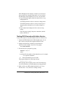
Chapter 4 Testing and Troubleshooting
Using the Test Software . . . . . . . . .
Installing the Test Software . . . . . .
Changing the TR114 Configuration . .
Setting the Country Code . . . . .
Testing the Configuration . . . . . . .
Testing the Loop-Start Channels . . . . .
Faxtest Command Line Options . . .
Displaying Command Line Options
Sending a Test Fax . . . . . . . . . .
vi TR114 ISA Analog International Hardware Guide
4-1
4-2
4-3
4-4
4-4
4-5
4-5
4-6
4-6
Receiving a Test Fax . . . . .
Troubleshooting . . . . . . . . . .
Some Typical Errors . . . . .
Sending the Test Results to a File
Rebooting the Operating System .
.
.
.
.
.
.
.
.
.
.
.
.
.
.
.
.
.
.
.
.
.
.
.
.
.
.
.
.
.
.
.
.
.
.
.
.
.
.
.
.
.
.
.
.
.
. 4-6
. 4-7
. 4-7
4-11
4-11
.
.
.
.
.
.
.
.
.
.
.
.
.
.
.
.
.
.
.
.
.
.
.
.
.
.
.
.
.
.
.
.
.
.
.
.
.
.
.
.
.
.
Chapter 5 Contacting Technical Support
Getting Technical Support . . . . . . .
Contacting Belgium . . . . . . . . .
Contacting Japan . . . . . . . . . .
Contacting Singapore . . . . . . . .
Contacting USA . . . . . . . . . . .
Downloading Software from the FTP Site
Returning a Defective TR114 Board . .
.
.
.
.
.
.
.
5-1
5-2
5-2
5-2
5-2
5-3
5-4
Appendix A Installing and Testing
Hong Kong DID Service
Requirements for DID . . . . . . . . . . . . . . . . . A-1
DID Telephone Service . . . . . . . . . . . . . . . . A-1
DID Operation . . . . . . . . . . . . . . . . . . . A-2
Installing the TR114 DID Board . . . . . . . . . . . . A-3
Installing a Power Supply for DID Service . . . . . . A-3
Connecting a Computer Products Universal Power
Supply . . . . . . . . . . . . . . . . . . . . . . . A-4
Connecting to DID Service . . . . . . . . . . . . . . A-5
Testing the DID Channels . . . . . . . . . . . . . . . A-7
Changing the DID Configuration . . . . . . . . . A-7
Testing DID Channels without Active Service . . . A-8
Testing DID Channels with Active Service . . . . A-9
Troubleshooting Your DID Installation . . . . . . . A-10
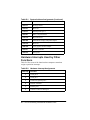
Appendix B Common System Resource Assignments
Addresses Used by Other Devices . . . . . . . . . . B-1
Hardware Interrupts Used by Other Functions . . . . B-2
DMA Channels Used by Other Functions . . . . . . . B-3
Index
vii
Preface
About This Manual
This hardware guide describes how to install the TR114 ISA analog
board, connect the board to the telephone service, and test your
installation.
Audience
The guide is written for those who install and configure telephony
boards.
The information in this guide is intended for users in countries
outside of North America. Chapter 3, Country Codes, Redialing
Restrictions and Cable Descriptions provides specific information for
the countries covered by this manual.
Related Documents
TR114 Firmware Installation and Release Notes
The following documents are available for developers:
Fax, Voice, and Data API V4.0, Volume 1, User’s Guide
Fax, Voice, and Data API V4.0, Volume 2, Programmer’s Reference
ix
Manual Conventions
This manual uses the following conventions of notation:
• Italics denote file names, directory names and program
names, for example, “the btcall.cfg file”.
• The Courier font in bold indicates a command sequence
entered by the user at the system prompt, for example:
cd /usr/sys/bfax/app.src
• The Courier font not bolded indicates system output, for
example:
c:>Files installed.
• The icon below indicates a Caution note, meaning that the
software or hardware may be damaged if the precautions
described in the note are not observed.
x TR114 ISA Analog International Hardware Guide
Chapter 1
Introduction
The TR114 family of analog fax boards consists of one-channel,
two-channel and four-channel models for use in computers with
ISA/EISA buses. The TR114 can be used for many applications,
including fax broadcast, fax-on-demand, fax store and forward, LAN
fax servers, e-mail to fax services, and combined voice and fax
applications.
TR114 Models
Brooktrout offers the following TR114 ISA analog boards for
loop-start telephone service:
TR114+I1L - One loop-start channel
(Not available in all countries)
TR114+I2L - Two loop-start channels
TR114+I4L - Four loop-start channels
The cables and connectors that Brooktrout supplies for these boards
conform to the specific needs of the country in which they are used.
Chapter 3, Country Codes, Redialing Restrictions, Compliance, and
Cable Descriptions describes the cables and connectors in detail by
country.
Brooktrout also supplies TR114 ISA analog boards for use with
Direct Inward Dial (DID) service in Japan and Hong Kong. See the
Japanese and Hong Kong descriptions in Chapter 3.
1-1
Features
The TR114 boards provide high-performance fax and voice systems:
• One, two, or four independent fax and/or voice channels in
one 16-bit ISA or EISA bus slot.
• Full Group 3 fax send-and-receive functionality on each
channel, with advanced features, such as Error Correction
Mode, Binary File Transfer, and MH, MR, or MMR
compression.
• Speech record and playback.
Each channel can record and play back ADPCM and PCM,
permitting you to build a variety of fax and voice systems
using a single TR114, such as voice prompted fax retrieval
systems, fax mail systems with voice annotation capability,
and integrated voice/fax mail systems.
• DTMF (Touch Tone), SIT, CNG, and CED detection
capability.
• Auto conversion of ASCII, MH, MR, MMR, TIFF, and
PCX/DCX files.
• Onboard forms overlay capability. Increases efficiency and
throughput of high-volume forms-based fax applications.
• Automatic reduction or expansion of the page width on
transmission.
• Adaptive in-band call progress detection capability that
works world-wide.
• Downloadable firmware.
You can easily install updates from a floppy diskette or
from the Brooktrout web site to add new system
functionality.
• LED status indicators.
• Direct Memory Access (DMA) and Programmed I/O (PIO)
data transfer capability for efficient, multichannel support.
• Support for 11 hardware interrupts.
• Application Programmer's Interface tools and software
drivers that work with the following operating systems:
1-2 TR114 ISA Analog International Hardware Guide
AT&T UNIX System V, release 3.2, 4.0
IBM AIX for PowerPC V4.1
MS-DOS release 3.0 and higher
OS/2 release 2.0 and higher
QNX release 2/3, 4.2x
SCO UNIX System V, release 3.2
SCO Xenix/386 System V
Sunsoft Solaris V2.4 and higher
UnixWare System V, release 4.2 V1.1, V2.0
Windows NT, version 3.1 and higher
Windows 95
System Requirements
• One 16-bit slot in any computer with an ISA or EISA
expansion bus.
If you use an EISA slot, you may need to create an EISA
configuration file for the board as explained on page 2-8.
• One hardware interrupt.
All TR114 ISA boards in the system must share the same
interrupt.
• One DMA channel selected through software (optional).
• A block of consecutive I/O addresses:
- 8 addresses to support the TR114+I1L
- 12 addresses to support the TR114+I2L
- 20 addresses to support the TR114+I4L
• Telephone service: loop-start (analog, single-line
extensions for PBX or Key telephone systems) or DID (for
Japan and Hong Kong only).
Introduction
1-3
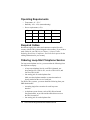
Operating Requirements
• Temperature: 0° - 50° C
• Humidity: 10% - 95% (noncondensing)
• Power requirements (±5%):
Type
+5VDC +12VDC
-12VDC
Total Power
1-channel
1A
5 mA
10 mA
5.2 W
2-channel
1.5 A
5 mA
20 mA
7.8 W
4-channel
2.5 A
5 mA
35 mA
12.98 W
Required Cables
Brooktrout supplies the cables and connectors required for each
country with the TR114 board shipped to that country. If you wish to
make cables for your TR114, see Chapter 3, Country Codes,
Redialing Restrictions, Compliance, and Cable Descriptions for the
cabling information for your country.
Ordering Loop-Start Telephone Service
For loop-start telephone service, you must order the following from
the telephone company:
• A loop-start telephone line for each TR114 channel; one
loop-start line for a TR114+I1L, two for a TR114+I2L, and
four for a TR114+I4L.
• One analog jack for each telephone line.
Make sure the telephone number or extension number is
clearly marked on the cover of each jack.
For PBX or Key systems, you must obtain the following from your
PBX administrator:
• An analog single-line extension for each loop-start
interface.
• A telephone system feature, such as DIL (Direct Inward
Line termination), to provide outside callers direct access to
the TR114 extension.
• One analog jack for each telephone line.
1-4 TR114 ISA Analog International Hardware Guide
Chapter 2
Configuring and Installing
the TR114
This chapter explains how to configure and install a TR114 ISA
analog board. Instructions are also provided for connecting to
loop-start telephone service. For connecting to Japanese DID service,
refer to the Japanese information in Chapter 3. For connecting to
Hong Kong DID service, refer to Appendix A, Installing and Testing
Hong Kong DID Service.
The following tasks are required to set up and install a TR114 board:
• Configure the hardware
• Install the TR114 board in the computer
• Connect the cables
• Install the software
• Configure the software
- DMA channel
- Country code
2-1
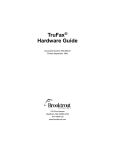
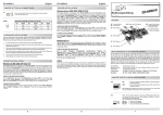
Hardware Description
Figure 2-1 shows the layout of a TR114+I4L (daughter boards are not
shown).
O
N
1 2 3 4 5 6 7 8
Address Switch (SW1)
3
4
5
6
7
9
10 11 12 14 15
Interrupt set to 5
Set to 260 (hex)
DB9 or RJ-45 Jacks
LEDs for TR114 Channels
ISA Bus Connector
Mounting Bracket
Figure 2-1. TR114+I4L ISA Analog Board
Note: The address switches are shown as they appear
when you hold the TR114 board upright, with the
front of the board facing you and the mounting
bracket to the right.
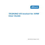
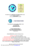
Figure 2-2 shows the mounting brackets for the TR114 ISA analog
boards. The TR114 board for your country may have a DB9 jack or
RJ-45 jacks on the mounting bracket. DID versions of the board also
have a power supply plug below the telephone jacks.
2-2 TR114 ISA Analog International Hardware Guide
RJ-45 Jacks
DB9 Jack
0123
01
TR114+I1L and I2L
0123
Channel LEDs
TR114+I4L
TR114+I1L, I2L and I4L
Figure 2-2. TR114 Mounting Brackets: RJ-45 and DB9
Connectors
LED Activity
The LEDs indicate the activity of their associated TR114 channels:
• Flash when the computer is powered up.
• Flash periodically when firmware is downloaded to the
board.
• Flash more rapidly when the channel goes off hook.
• Flash when the channel os receiving data from the host.
The LEDs can be useful for troubleshooting problems.
Configuring the Board
To configure the TR114 board for operation in any system, you must:
• Set a unique base address.
• Set the hardware interrupt.
• Select the DMA or PIO channel via software.
Configuring and Installing the TR114
2-3
Default Configuration Settings
You can quickly set up and install the TR114 board by accepting the
following factory-assigned settings:
• Base I/O address =
260 hex
• Hardware interrupt = 5
• Data transfer mode = DMA channel 1 (software selectable)
Changing the Default Settings
In some cases, you will not be able to use all the factory-assigned
settings and will have to change one or more configuration options.
The following sections describe how to change the settings.
Setting the Base Address
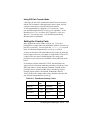
Each TR114 board requires assignment of a unique block of
addresses to enable communication between the TR114 board and the
host. This address block is subdivided into smaller blocks, each
consisting of four addresses. Each channel on a TR114 board uses a
4-address block, and the TR114 board uses one for communication
with the host. The number of consecutive I/O addresses required by a
TR114 ISA board depends on the number of channels on the board as
shown in Table 2-1.
Table 2-1. I/O Addresses Required
Board
Consecutive I/O Addresses
1-channel
8 (8 hex)
2-channel
12 (C hex)
4-channel
20 (14 hex)
These I/O addresses must not overlap with those of any other TR114
board or other devices installed in the system.
The base address, a three-digit hex number, is the first address in the
assigned block. Set the base address of the TR114 board using the
base address switches shown in Figure 2-1. The base address is set to
260 (hex) in the figure.
2-4 TR114 ISA Analog International Hardware Guide
If you need to set the base address to another address, we recommend
using one of the following addresses: 100, 140, 180, 200, 220, 240,
260, 280, 2A0, and 2C0. To set the base I/O address to one of those
recommended, set switches 2 through 8 of the base address switches
ON (toward the board) or OFF (away from the board) as shown in
Table 2-2.
Table 2-2. Switch Settings for Recommended Base I/O
Addresses
Base I/O
Address
Switch
8
7
6
5
4
3
2
100
ON
OFF
ON
ON
ON
ON
ON
140
ON
OFF
ON
OFF
ON
ON
ON
180
ON
OFF
OFF
ON
ON
ON
ON
200
OFF
ON
ON
ON
ON
ON
ON
220
OFF
ON
ON
ON
OFF
ON
ON
240
OFF
ON
ON
OFF
ON
ON
ON
260
OFF
ON
ON
OFF
OFF
ON
ON
280
OFF
ON
OFF
ON
ON
ON
ON
2A0
OFF
ON
OFF
ON
OFF
ON
ON
2C0
OFF
ON
OFF
OFF
ON
ON
ON
You can select a valid base address from the range of hex numbers
between 100 and 3F8 that end in 0 or 8.
Note: Switch 1 does not affect the base address; it enables
an interrupt pull-up and must be ON on only one
TR114 board in a system.
Switches 2 through 8 set the individual digits in the TR114 board’s
base address. Switches 8 and 7 set the first digit of the base address,
switches 6 through 3 set the middle digit of the base address, and
switch 2 sets the third digit as shown in Table 2-3.
Configuring and Installing the TR114
2-5
Table 2-3. Switch Settings for the Base Address
Hex
Value
Switches
8
7
6
5
4
3
1xx
ON
OFF
2xx
OFF
ON
3xx
OFF
OFF
x0x
ON
ON
ON
ON
x1x
ON
ON
ON
OFF
x2x
ON
ON
OFF
ON
x3x
ON
ON
OFF
OFF
x4x
ON
OFF
ON
ON
x5x
ON
OFF
ON
OFF
x6x
ON
OFF
OFF
ON
x7x
ON
OFF
OFF
OFF
x8x
OFF
ON
ON
ON
x9x
OFF
ON
ON
OFF
xAx
OFF
ON
OFF
ON
xBx
OFF
ON
OFF
OFF
xCx
OFF
OFF
ON
ON
xDx
OFF
OFF
ON
ON
xEx
OFF
OFF
OFF
ON
xFx
OFF
OFF
OFF
OFF
2
xx0
ON
xx8
OFF
To ensure a unique base address for each TR114 ISA board when you
install multiple TR114 ISA boards in a system, add or subtract from
the base address of the other TR114 boards:
• 6 (hex) for 1-channel boards.
• 10 (hex) for 2-channel boards.
• 18 (hex) for 4-channel boards.
2-6 TR114 ISA Analog International Hardware Guide
For example, if you have three TR114 ISA boards in your system,
you can select:
Example 1:
Example 2:
Example 3:
Board 1
Base Address
Board 2
Base Address
Board 3
Base Address
228
250
260
240
268
278
258
280
290
Setting the Hardware Interrupt
The TR114 board generates interrupts to the host computer. These
interrupts are handled by the TR114 device driver.
See Figures Figure 2-1 for the interrupt header, which is shown set to
interrupt 5.
Note: All TR114 ISA boards (and all other TR series ISA
boards) installed in the same system must be set to
share the same hardware interrupt.
The TR114 board can use interrupts 3, 4, 5, 6, 7, 9, 10, 11, 12, 14, or
15.
In order of preference, we recommend using interrupt 5, 10, 12, or 15.
To set the hardware interrupt, move the jumper to the pair of pins of
the interrupt header that corresponds to the hardware interrupt you
want to use. The pins are numbered left to right as shown in
Figure 2-1.
Using ISA Boards with Plug and Play
Boards
The computer BIOS automatically configures the addresses and
hardware interrupts (IRQs) for PCI and plug and play boards, which
may change when the system is rebooted, especially if devices are
added or moved. The BIOS does not recognize the ISA boards in your
system when configuring the PCI and plug and play boards. Interrupts
can be shared among PCI boards, but not between PCI boards and
ISA boards.
Configuring and Installing the TR114
2-7
The action you take to resolve conflicts among the various boards
depends on your brand of computer. Check the manufacturer’s
instructions for techniques for avoiding conflicts. See Appendix B,
Common System Resource Assignments for more information.
Generally, you can avoid conflicts among ISA, PCI, and plug and
play boards by doing the following:
• Let the computer BIOS configure all the PCI and plug and play
boards.
• Use the tools supplied with the computer to determine the
interrupts used or reserved by other devices in your computer.
For example, Dell computers have an ISA Configuration Utility
to track and reserve the installed ISA boards and the resources
they use.
• Choose an unused interrupt and address for the TR114 ISA
boards. All TR114 ISA boards share an IRQ, but TR114 ISA
and PCI boards in the same system use different IRQs.
Using ISA Boards in EISA Slots
If you install ISA boards in EISA slots, use an EISA configuration
utility to create an EISA configuration file to reserve the interrupt, I/O
addresses, and DMA (if used) for the TR114 board. The computer
BIOS will not use the reserved interrupt, addresses, and DMA for
other devices in your computer. Brooktrout does not supply EISA
configuration files for the TR114 ISA board. Check the computer
manufacturer’s documentation for instructions on creating an EISA
configuration file.
If you are installing multiple TR114 ISA boards in EISA slots, create
an EISA configuration file for each slot and specify the unique base
I/O address of each board in its respective slot. However, you must
enter the interrupt for only one of the TR114 slot configurations even
though multiple TR114 ISA boards share the same interrupt. This is
because EISA configuration utilities do not allow an interrupt to be
entered more than once.
2-8 TR114 ISA Analog International Hardware Guide
If you cannot find a free interrupt, you may be able to disable an LPT
port or a COM port that is not being used. These ports can be disabled
in the BIOS on some computers. On older computers, it may require a
change to a jumper setting on the motherboard. Once the port is
disabled, its associated interrupt becomes available.
Installing the TR114 ISA Board in the
Computer
After configuring the board, you are ready to install the TR114 board
in your computer. We recommend you keep a record of the addresses
and interrupt setting used in the configuration. You will need these
values later when you configure your software. To install the board:
CAUTION
The TR114 is an electrostatic-sensitive
device. Follow proper ESD procedures
when handling the board.
1. Power off the computer.
2. Remove the computer’s cover. If the system has a board
hold-down bar, remove it as well.
3. Locate an unused expansion slot and remove the bracket for
it.
4. Holding the TR114 at each top corner, insert the board
firmly into the ISA or EISA slot.
5. Screw the TR114's mounting bracket securely to the
computer's frame.
6. Connect the telephone cable (see Connecting to the
Telephone Service).
7. Turn on the computer.
Once you have installed the board, you can test the board by running
the faxtest program (see Chapter 4, Testing and Troubleshooting) and
then install the software. Or you can install the software immediately.
Configuring and Installing the TR114
2-9
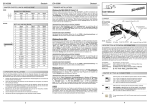
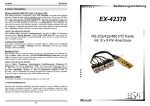
Connecting to the Telephone Service
Connect the TR114 to loop-start telephone service using the
following procedures.
1. Locate the cable(s) supplied with your TR114 board. Refer
to Chapter 3, Country Codes, Redialing Restrictions,
Compliance, and Cable Descriptions for the number and
type of cables you should have, and whether you require
adapters.
2. Plug the end with a DB9 or RJ-45 connector into the jack
on the TR114 board (see Figure 2-3).
See Chapter 3 for
your cable type
TR114 ISA Analog Board
Wall Jacks
Figure 2-3. Connecting TR114 Cables to Telephone
Service
3. If your cable requires adapters, attach each adapter to an
RJ-11 plug (see Figure 2-4). If your cable does not require
adapters, go to step 4.
TR114
Adapter
RJ-11 Plugs
DB9 Plug
Figure 2-4. Attaching an Adapter to Your Cable
4. Plug the other end of the cable into a loop-start
wall-mounted telephone jack, as shown in Figure 2-3.
The TR114 is now connected to the telephone service.
See Appendix A for isntructions on connecting to DID service.
2-10 TR114 ISA Analog International Hardware Guide
Installing the Software
You need to install the software to run the boards. If you are an
application developer, install the Brooktrout-supplied driver, API,
and firmware. If you use software from another vendor, see that
vendor’s manual for instructions on installing software.
Installing the Brooktrout Software
The Brooktrout API and driver are available for a variety of operating
systems. See the Brooktrout Fax, Voice, and Data API User’s Guide
for information on installing the API and driver for a specific
operating system.
The TR114 firmware is included on a single DOS-formatted diskette.
Before running any applications that use the TR114 board, consult the
TR114 Firmware Installation and Release Notes for detailed
instructions on how to copy the contents of this diskette onto your
hard disk. The Brooktrout API/driver downloads the firmware for
you.
Installing LAN Fax Software
If you use software from another vendor, the firmware is, in most
cases, already be included with the software, which automatically
downloads the firmware to the board.
See your LAN fax application’s user manual for instructions on
installing your LAN fax software. After you have set up your LAN
fax software to support the TR114 board, you can begin sending and
receiving faxes.
Configuring the Software
After your board and software are installed, you may need to make
changes to the software configuration. If you changed the base I/O
address or the interrupt on the board, you can set the new values when
you install the driver and initialize the board.
You can set the data transfer method when installing the driver or in
the user-defined configuration file (default name, btcall.cfg).
You also set the country code for your board in the user-defined
configuration file.
Configuring and Installing the TR114
2-11
Selecting the Data Transfer Method
The TR114 ISA board can transfer data to and from the host
computer in Programmed I/O (PIO) mode or in Direct Memory
Access (DMA) mode.
The Brooktrout driver and API software selects DMA channel 1 for
data transfers by default. However, you can select another DMA
channel when you install the driver. For detailed instructions on
installing the driver for your operating system, see the Brooktrout
Fax, Voice, and Data Application Programming Interface User’s
Guide.
With Brooktrout software, you can also set the data transfer method
using the dma keyword in the user-defined configuration file,
btcall.cfg. see Appendix C in the Brooktrout Fax, Voice, and Data
Application Programming Interface Programmer’s Reference
Manual.
If you use a driver from another vendor, see that vendor’s manual for
instructions on installing the driver and selecting PIO or a DMA
channel.
Using DMA Transfer Mode
Under DMA, the DMA driver controls data transfers between
memory and the TR114 channels. Although using DMA may take a
little longer than PIO, using DMA may increase system performance
because the host computer can process other jobs during the transfer.
All TR114 ISA boards (and all TR series ISA boards) Iinstalled in the
same system must share the same DMA channel.
You can use DMA channels 0 through 3 and 5 through 7 (channels
0–3 use only 8 bits while channels 5–7 use 16 bits). The system
reserves DMA channel 4 for its own use. In order of preference, we
recommend using DMA channel 7 or 1.
In addition to the TR114, other boards, devices, and software use
particular DMA channels. To avoid conflicts, select an unused DMA
channel or disable or move any device that competes for the DMA
channel you select. Appendix B, Common System Resource
Assignments, lists some of the functions that systems may assign to
particular DMA channels.
2-12 TR114 ISA Analog International Hardware Guide
Using PIO Data Transfer Mode
Under PIO, the host CPU controls data transfers between memory
and the TR114 channels. Although transfer time is faster, the host
computer cannot process other jobs during the transfer.
To use Programmed I/O, change the dma keyword to 0 in the
user-defined configuration file, btcall.cfg (see Appendix C of the
Brooktrout Fax, Voice, and Data API Programmer’s Reference
Manual). You can also select -1 for the DMA option during
Brooktrout driver installation.
Setting the Country Code
Many applications set the country code for you. If you were
prompted for a country when you installed the software, the code was
probably set correctly. You can check the country_code keyword
in the user-defined configuration file, btcall.cfg, to verify it.
A sticker on the back of the board indicates the country in which the
board is approved for use; for example, a board marked “TR114 UK”
is approved for use in the United Kingdom. The county code
parameter in your software must match the country indicated on the
board.
If a board has a sticker marked EC CTR21, that board has been
approved for the European community and can be used in any of the
following contries: Austria, Belgium, Denmark, Finland, France,
Germany, Greece, Iceland, Ireland, Italy, Luxembourg, Norway,
Portugal, Spain, Sweden, Switzerland, Netherlands, and UK.
Table 2-4 shows the country codes as they should be entered in the
user-defined configuration file, btcall.cfg.
Table 2-4. Brooktrout Country Codes
Country
Country
Code
Country
Country
Code
Australia
610
Netherlands
310
Denmark
450
New Zealand
640
EC CTR 21
190
Norway
470
France
330
Singapore
650
Configuring and Installing the TR114
2-13
Table 2-4. Brooktrout Country Codes (Continued)
Country
Country
Code
Country
Country
Code
Germany
490
Spain
340
Ireland
3530
Sweden
460
Italy
390
Switzerland
410
Hong Kong
8520
United Kingdom
440
United States
10
Japan
See page 3-18
Malaysia
600
Checking the Bt_cparm.cfg File
Country codes are maintained in the country-specific configuration
file, bt_cparm.cfg (a read-only file); the btcall.cfg file uses the
country code parameters from this file. If the appropriate parameter
for your country is not in the bt_cparm.cfg file, the US default value
(10) is used. You can check for your country code in the country.h
file that comes with bt_cparm.cfg.
If the code for your country is not in the bt_cparm.cfg file, you need
to download the latest version of the file from the Brooktrout ftp site,
as follows:
ftp.brooktrout.com/support/country/cparm.exe
This downloads a program that contains various versions of the
bt_cparm.cfg file. You can expand the program using
cparm -d.
You must use the bt_cparm.cfg file for the version of the Brooktrout
API that you used to develop your application; for example, if you
used API V3.7 to develop your application, you must use the
subdirectory, 3.7.
2-14 TR114 ISA Analog International Hardware Guide
Chapter 3
Country Codes, Redialing
Restrictions, Compliance,
and Cable Descriptions
This chapter lists the country code and describes the cabling
information for your country, including the pinouts in case you wish
to build your own cable. Dialing restrictions and compliance
regulations are also included for those countries where applicable.
Country Code:
The country code for your country is shown as it should be entered in
the user-defined configuration file (BTCALL.CFG is the default
filename).
Redialing Restrictions and Compliance Regulations:
If your country has restrictions for redialing or regulations concerning
compliance, they are described in these sections.
Cable Information:
The details for the cables that are shipped with your TR114 ISA
analog boards are described in this section. The following
information is included:
Column Heading
Description
TR114 Model
The name of the TR114 as you ordered it from
Brooktrout, e.g., TR114+I4L
Cable Part Number and The Brooktrout part number for the cable and the
Quantity Required
number of cables shipped with the TR114 model.
Connectors:
Board → Wall
Specifies the connectors that connect the cable to
the TR114 (board end) and to the telephone
service (wall end), e.g., “DB9 → RJ-11” specifies
a DB9 connector to the TR114 and an RJ-11 to the
telephone service.
Pinout Abbreviations:
NC = Pin is loaded but not connected
NL = Pin is not loaded
Country Codes, Redialing Restrictions, Compliance, and Cable
Descriptions
3-1
Australia
Country Code
610
Compliance Regulations
You should include missing_wait 40 in the BT_CALL.CFG file.
Australian regulatory authorities recommend that the application
delay two seconds before answering an incoming call.
Cable Information
TR114 Model
TR114+I1L
TR114+I2L
TR114+I4L
Cable Part
Number
340-033-06
340-033-06
340-033-05
Quantity
Required
1
2
2
Connectors:
Board → Wall
RJ-45 → RJ-11
RJ-45 → RJ-11
RJ-45 → RJ-11
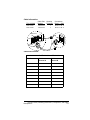
TR114+I4L
Wall Jack
Pin 1
Pin 1
RJ-11 Plugs
RJ-45 Plug
3-2 TR114 ISA Analog International Hardware Guide
Connector Pinouts:
340-033-05:
For TR114+I4L
340-033-06:
For TR114+I1L and I2L
RJ-45
RJ-11:
Channel A
RJ-11:
RJ-45
Channel B
RJ-11:
Channel A
1 - NC
1 - NL
1 - NL
1 - NC
1 - NL
2 - NC
2 - NC
2 - NC
2 - NC
2 - NC
3 - Yellow
3 - Red
3 - Yellow
3 - NC
3 - Red
4 - Red
4 - Green
4 - Black
4 - Red
4 - Green
5 - Green
5 - NC
5 - NC
5 - Green
5 - NC
6 - Black
6 - NL
6 - NL
6 - NC
6 - NL
7 - NC
7 - NC
8 - NC
8 - NC
Country Codes, Redialing Restrictions, Compliance, and Cable
Descriptions
3-3
Denmark
Country Code
450
Cable Information:
TR114 Model
Cable Part
Number
TR114+I2L
TR114+I4L
340-036-02
340-036-02
Quantity
Required
1
2
Connectors:
Board → Wall
RJ-45 → RJ-11
RJ-45 → RJ-11
TR114+I4L
Wall Jack
Pin 1
Pin 1
RJ-11 Plugs
RJ-45 Plug
3-4 TR114 ISA Analog International Hardware Guide
Connector Pinouts:
340-036-02: For TR114+I2L and TR114+I4L
RJ-45
RJ-11:
Channel A
RJ-11:
Channel B
1 - NC
1 - NL
1 - NL
2 - NC
2 - NC
2 - NC
3 - Yellow
3 - Green
3 - Black
4 - Green
4 - Red
4 - Yellow
5 - Red
5 - NC
5 - NC
6 - Black
6 - NL
6 - NL
7 - NC
8 - NC
Country Codes, Redialing Restrictions, Compliance, and Cable
Descriptions
3-5
European Community-CTR21
Country Code
190
Compliance Regulations
With respect to 98/482/EC, Annex II
This equipment has been approved in accordance with Council
Decision 98/482/EC for pan-European single terminal connection to
the Public Switched Telephone Network (PSTN). However, due to
differences between the individual PSTNs provided in different
countries, the approval does not, of itself, give an unconditional
assurance of successful operation on every PSTN network
termination point.
In the event of problems, you should contact your equipment supplier
in the first instance.
With respect to 98/482/EC, Annex III
This equipment is designed to operate correctly on the networks of
Austria, Belgium, Denmark, Finland, France, Germany, Greece,
Iceland, Ireland, Italy, Luxembourg, Norway, Portugal, Spain,
Sweden, Switzerland, Netherlands, and UK.
Operational problems may occur in Spain when this equipment is
installed at a great distance from the central exchange.
This equipment is not designed to be installed in series with any other
telecommunications equipment. Installation of this equipment in
parallel with other telecommunications equipment may result in
malfunction.
There are no adjustments required to use this equipment on the above
listed networks.
Redialing Restrictions
For transmission of any one document to any one telephone number,
the application must:
• Make no more than fifteen call attempts
• Delay five seconds between successive call attempts to the
same number.
3-6 TR114 ISA Analog International Hardware Guide
Cable Information:
TR114 Model
TR114+I2L
TR114+I4L
Cable Part
Number
340-036-02
340-036-02
Quantity
Required
1
2
Connectors:
Board → Wall
RJ-45 → RJ-11
RJ-45 → RJ-11
TR114+I4L
Wall
Pin 1
Pin 1
RJ-11
RJ-45
Connector Pinouts:
340-036-02: For TR114+I2L and TR114+I4L
RJ-45
RJ-11:
Channel A
RJ-11:
Channel B
1 - NC
1 - NL
1 - NL
2 - NC
2 - NC
2 - NC
3 - Yellow
3 - Green
3 - Black
4 - Green
4 - Red
4 - Yellow
5 - Red
5 - NC
5 - NC
6 - Black
6 - NL
6 - NL
7 - NC
8 - NC
Country Codes, Redialing Restrictions, Compliance, and Cable
Descriptions
3-7
France
Country Code
330
Redialing Restrictions
Unsuccessful calls can be inefficient calls or wrong calls. Inefficient
calls occur when the called number fails to answer. In this case, the
API reports BUSY1, BUSY2, ROBUSY, RECALL, DIALTON, SIT_,
or RNGNOANS. Wrong calls occur when the called number answers
but fails to send fax CED tone or V.21 signal to indicate a fax
machine. In this case the API reports HUMAN, QUIET, SILENCE, or
ANSWER.
• For applications that differentiate between inefficient calls
and wrong calls, the application must:
- Make no more than six call attempts per hour.
- Delay from one to twelve minutes between each call
attempt.
- When it detects a wrong call twice during the hour, add
the telephone number to the blacklist and make no more
attempts to send any document to that telephone number.
• For applications that do not differentiate between
inefficient calls and wrong calls, the application must:
- Make no more than six call attempts per hour.
- Delay from one to twelve minutes between each call
attempt.
- After six failed attempts to detect an answering fax
machine, add the telephone number to the blacklist and
make no more attempts to send any document to that
telephone number.
• Only an operator issuing the command manually can
remove a telephone number from the blacklist.
3-8 TR114 ISA Analog International Hardware Guide
Cable Information:
TR114 Model
Cable Part
Number
TR114+I1L
TR114+I2L
TR114+I4L
340-062-01
340-050-02
340-050-01
Quantity
Required
1
1
1
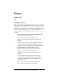
Connectors:
Board → Adapter
DB9 → RJ-11-to-France
DB9 → RJ-11-to-France
DB9 → RJ-11-to-France
TR114+I4L
RJ-11 Adapter
9
6
1
5
Pin 1
Pin 1
RJ-11 Plugs
DB9 Plug
Connector Pinouts:
340-050-01:
For TR114+I4L
DB9
RJ-11
1 - Red
1 - NL
2 - Red
2 - NL
3 - NC
3 - Red
4 - Red
4 - Green
5 - Red
5 - NL
6 - Green 6 - NL
7 - Green
8 - Green
9 - Green
340-050-02:
For TR114+I2L
DB9
RJ-11
1 - Red
1 - NL
2 - Red
2 - NL
3 - NC
3 - Red
4 - NC
4 - Green
5 - NC
5 - NL
6 - Green
6 - NL
7 - Green
8 - NC
9 - NC
340-062-01:
For TR114+I1L (Ch. 0)
DB9
RJ-11
1 - NC
1 - NL
2 - Red
2 - NL
3 - NC
3 - Red
4 - NC
4 - Green
5 - NC
5 - NL
6 - Green
6 - NL
7 - NC
8 - NC
9 - NC
Country Codes, Redialing Restrictions, Compliance, and Cable
Descriptions
3-9
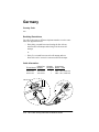
Germany
Country Code
490
Redialing Restrictions
For calls to the same or different telephone numbers over the same
trunk, the application must:
• Delay thirty seconds between releasing the line after an
unsuccessful call attempt and seizing it for the next call
attempt,
or
• Delay five seconds between each call attempt and two
hours after twelve successive unsuccessful call attempts.
Cable Information:
Cable Part
TR114 Model Number
TR114+I2L
TR114+I4L
340-050-04
340-050-03
Quantity
Required
1
1
Connectors:
Board → Wall
DB9 → R1 (TAES 6N)
DB9 → R1 (TAES 6N)
TR114+I4L
Pin 4
Pin 5
Pin 6
9
6
5
1
Pin 3
Pin 2
Pin 1
Pin 1
R1 Plugs
DB9 Plug
3-10 TR114 ISA Analog International Hardware Guide
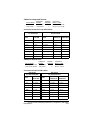
Connector Pinouts:
340-050-03:
For TR114+I4L
340-050-04:
For TR114+I2L
DB9
R1
DB9
R1
1 - Red
1 - Red
1 - Red
1 - Red
2 - Red
2 - Green
2 - Red
2 - Green
3 - NC
3 - NL
3 - NC
3 - NL
4 - Red
4 - NL
4 - NC
4 - NL
5 - Red
5 - NL
5 - NC
5 - NL
6 - Green
6 - NL
6 - Green
6 - NL
7 - Green
7 - Green
8 - Green
8 - NC
9 - Green
9 - NC
Country Codes, Redialing Restrictions, Compliance, and Cable
Descriptions
3-11
Hong Kong
Note: Both loop-start and DID boards are available for Hong
Kong. Connecting to loop-start service is described in
Chapter 2, Configuring and Installing the TR114.
Connecting to DID service is described in Appendix A,
Installing and Testing Hong Kong DID Service.
Country Code
8520
Compliance Regulations
The TR114 uses a standard 2-wire connection to the modular socket
and therefore may be incompatible with CPEs that utilize 3-wire
connections. (A CPE is any telephone product that is approved for
connection to the phone network.)
To ensure proper operation, no more than four (4) CPEs should be
installed on one exchange line.
Redialing Restrictions
For transmissions of any one document to any one telephone number,
over the same trunk, the application must make no more than eleven
(11) call attempts. There are no restrictions on the interval between
each call attempt.
The application must not attempt to transmit documents to 999
numbers.
Cabling Information
TR114+I4L
Pin 1
Pin 1
431A Plugs
RJ-45
3-12 TR114 ISA Analog International Hardware Guide
Cables for Loop-start Service:
TR114 Model
Cable Part
Number
Quantity
Required
TR114+I2L
TR114+I4L
340-038-02
340-038-00
Connectors:
Board → Wall
RJ-45 → 431A UK
RJ-45 → 431A UK
2
2
Connector Pinouts for Loop-start Cables:
340-038-02:
For TR114+I2L
340-038-00:
For TR114+I4L
RJ-45
431A UK
RJ-45
431A UK
431A UK
Channel A Channel B
1 - NC
1 - NC
1 - NC
1 - NL
1 - NL
2 - NC
2 - Green
2 - NC
2 - Green
2 - Green
3 - NC
3 - NC
3 - Green
3 - NC
3 - NC
4 - Green
4 - NC
4 - Green
4 - NC
4 - NC
5 - Red
5 - Red
5 - Red
5 - Red
5 - Red
6 - NC
6 - NC
6 - Red
6 - NL
6 - NL
7 - NC
7 - NC
8 - NC
8 - NC
Cables for DID Service:
TR114 Model
Cable Part
Number
TR114+I2C & I2D
TR114+I4C & I4D
340-148-40
340-148-30
Quantity
Required
2
2
Connectors:
Board → Wall
RJ-45 → RJ-11
RJ-45 → RJ-11
Connector Pinouts for DID Cables:
340-148-40:
For TR114+I2C & D
340-148-30:
For TR114+I4C & D
RJ-45
431A UK
RJ-45
431A UK
431A UK
Channel A Channel B
1 - NC
1 - NC
1 - NC
1 - NL
1 - NL
2 - NC
2 - Green
2 - NC
2 - Green
2 - Green
3 - NC
3 - NC
3 - Red
3 - NC
3 - NC
4 - Green
4 - NC
4 - Green
4 - NC
4 - NC
5 - Red
5 - Red
5 - Red
5 - Red
5 - Red
6 - NC
6 - NC
6 - Green
6 - NL
6 - NL
7 - NC
7 - NC
8 - NC
8 - NC
Country Codes, Redialing Restrictions, Compliance, and Cable
Descriptions
3-13
Ireland
Country Code
3530
Redialing Restrictions
For calls to the same telephone number over the same trunk, the
application must:
• Delay five seconds between the first and second call
attempt.
• Delay sixty seconds between each subsequent call attempt.
• Make no more than four call attempts in one hour.
Cable Information:
TR114 Model
Cable Part
Number
TR114+I2L
TR114+I4L
340-036-02
340-036-02
Quantity
Required
1
2
Connectors:
Board → Wall
RJ-45 → RJ-11
RJ-45 → RJ-11
TR114+I4L
Wall Jack
Pin 1
Pin 1
RJ-11 Plugs
RJ-45 Plug
3-14 TR114 ISA Analog International Hardware Guide
Connector Pinouts:
340-036-02:
For TR114+I2L and I4L
RJ-45
RJ-11:
Channel A
RJ-11:
Channel B
1 - NC
1 - NL
1 - NL
2 - NC
2 - NC
2 - NC
3 - Yellow
3 - Green
3 - Black
4 - Green
4 - Red
4 - Yellow
5 - Red
5 - NC
5 - NC
6 - Black
6 - NL
6 - NL
7 - NC
8 - NC
Country Codes, Redialing Restrictions, Compliance, and Cable
Descriptions
3-15
Italy
Country Code
390
Redialing Restrictions
For calls to the same telephone number over the same trunk, the
application must:
• Delay five seconds between the first and second call
attempt.
• Delay sixty seconds between each subsequent call attempt.
• Make no more than four call attempts in one hour.
Cable Information:
TR114 Model
Cable Part
Number
TR114+I2L
TR114+I4L
340-050-02
340-050-01
Quantity
Required
1
1
Connectors:
Board → Wall
DB9 → RJ-11
DB9 → RJ-11
TR114+I4L
Wall Jack
9
6
5
1
Pin 1
Pin 1
RJ-11 Plugs
DB9 Plug
3-16 TR114 ISA Analog International Hardware Guide
Connector Pinouts:
340-050-01:
For TR114+I4L
340-050-02:
For TR114+I2L
DB9
RJ-11
DB9
RJ-11
1 - Red
1 - NL
1 - Red
1 - NL
2 - Red
2 - NL
2 - Red
2 - NL
3 - NC
3 - Red
3 - NC
3 - Red
4 - Red
4 - Green
4 - NC
4 - Green
5 - Red
5 - NL
5 - NC
5 - NL
6 - Green
6 - NL
6 - Green
6 - NL
7 - Green
7 - Green
8 - Green
8 - NC
9 - Green
9 - NC
Country Codes, Redialing Restrictions, Compliance, and Cable
Descriptions
3-17
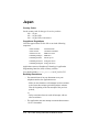
Japan
Country Codes
Set the country code for the type of service you have.
810 - 10 pps
812 - 10 pps, DID
814 - 10 pps, DID, Auto answer
Compliance Regulations
JATE has approved the TR114+I4L to run in the following
computers:
ACER 1100SX
ACER 1100X
ACER Power M
COMPAQ Deskpro
COMPAQ Proliant
COMPAQ ProLinea
COMPAQ ProSignia
FUJITSU FMV
GATEWAY 2000 P5
IBM PC/XT/AT
IBM PS/V
SONY QL-70
Wang 200 Series
Wang 300 Series
Applications must use Brooktrout Technology’s Application
Programming Interface (API) as library software.
You should include missing_wait 60 in BT_CALL.CFG.
Redialing Restrictions
• For transmissions of any one document to any one
telephone number, the application must:
- Make no more than three call attempts in a three-minute
period (new three-minute periods begin three minutes
after the beginning of the first attempt of the previous
period),
or
- Delay one minute between each call attempt, with no
other restrictions.
• The application must not attempt to transmit documents to
119 or 110 numbers.
3-18 TR114 ISA Analog International Hardware Guide
Cable Information:
Cable Part
TR114 Model Number
TR114+I2L
TR114+I4L
Quantity
Required
340-036-02
340-036-02
1
2
Connectors:
Board → Wall
RJ-45 → RJ-11
RJ-45 → RJ-11
TR114+I4L
Wall Jack
Pin 1
Pin 1
RJ-11 Plugs
RJ-45 Plug
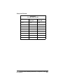
Connector Pinouts:
340-036-02:
For TR114+I2L and TR114+I4L
RJ-45
RJ-11:
Channel A
RJ-11:
Channel B
1 - NC
1 - NL
1 - NL
2 - NC
2 - NC
2 - NC
3 - Yellow
3 - Green
3 - Black
4 - Green
4 - Red
4 - Yellow
5 - Red
5 - NC
5 - NC
6 - Black
6 - NL
6 - NL
7 - NC
8 - NC
Country Codes, Redialing Restrictions, Compliance, and Cable
Descriptions
3-19
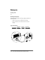
Malaysia
Country Code
600
Redialing Restrictions
For an unsuccessful attempt to dial any telephone number, the
application must:
• Make no more than two additional call attempts.
• Delay a minimum of two minutes between each call
attempt.
Cable Information:
TR114 Model
Cable Part
Number
TR114+I4L
340-036-02
Quantity
Required
2
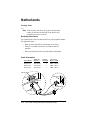
Connectors:
Board → Wall
RJ-45 → RJ-11
TR114+I4L
Wall Jack
Pin 1
Pin 1
RJ-11 Plugs
RJ-45 Plug
3-20 TR114 ISA Analog International Hardware Guide
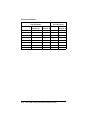
Connector Pinouts:
340-036-02: For TR114+I4L
RJ-45
RJ-11:
Channel A
RJ-11:
Channel B
1 - NC
1 - NL
1 - NL
2 - NC
2 - NC
2 - NC
3 - Yellow
3 - Green
3 -Black
4 - Green
4 - Red
4 - Yellow
5 - Red
5 - NC
5 - NC
6 - Black
6 - NL
6 - NL
7 - NC
8 - NC
Country Codes, Redialing Restrictions, Compliance, and Cable
Descriptions
3-21
Netherlands
Country Code
310
Note: If the country code in btcall.cfg does not match the
country on the label on the back of the board, calls
can neither be sent or received.
Redialing Restrictions
For transmissions of any one document to any one telephone number,
the application must:
• Make no more than fifteen call attempts in one hour.
• Delay five seconds between the first and second call
attempts.
• Delay one minute between each subsequent call attempt.
Cable Information:
TR114 Model
Cable Part
Number
TR114+I1L
TR114+I2L
TR114+I4L
340-062-01
340-050-07
340-050-01
Quantity
Required
1
1
1
Connectors:
Board → Wall
DB9 → RJ-11
DB9 → RJ-11
DB9 → RJ-11
TR114+I4L
Wall Jack
9
6
1
5
Pin 1
Pin 1
RJ-11 Plugs
DB9 Plug
3-22 TR114 ISA Analog International Hardware Guide
Connector Pinouts:
340-050-01:
For TR114+I4L
340-050-07:
For TR114+I2L
340-062-01:
For TR114+I1L (Ch. 0)
DB9
RJ-11
DB9
RJ-11
DB9
RJ-11
1 - Red
1 - NL
1 - NC
1 - NL
1 - NC
1 - NL
2 - Red
2 - NL
2 - Red
2 - NL
2 - Red
2 - NL
3 - NC
3 - Red
3 - NC
3 - Red
3 - NC
3 - Red
4 - Red
4 - Green
4 - Red
4 - Green
4 - NC
4 - Green
5 - Red
5 - NL
5 - NC
5 - NL
5 - NC
5 - NL
6 - Green
6 - NL
6 - Green
6 - NL
6 - Green
6 - NL
7 - Green
7 - NC
7 - NC
8 - Green
8 - NC
8 - NC
9 - Green
9 - Green
9 - NC
Country Codes, Redialing Restrictions, Compliance, and Cable
Descriptions
3-23
New Zealand
Country Code
640
Compliance Regulations
The computer that houses the TR114 board is classified as a
communications terminal. As with all mains powered electrical
equipment, there is a legal requirement for it to meet the requirements
of the New Zealand wiring regulations. It is the responsibility of the
computer supplier rather than the Telepermit System to ensure that
these requirements are met.
Immediately disconnect the equipment if
it becomes physically damaged, and
arrange for its disposal or repair.
CAUTION
The TR114 is not designed for installation in parallel with any other
piece of telecommunications equipment. It may not provide for the
effective hand-over of a call to or from a telephone connected to the
same line. The operation of this equipment on the same line as
telephones or other equipment with audible warning devices or
automatic ring detectors will give rise to bell tinkle or noise and may
cause false tripping of the ring detector. Should such problems occur,
the user is not to contact Telecom Faults Service.
This equipment must not be operated in such a manner as to cause a
nuisance to other customers.
Redialing Restrictions
• For all outgoing calls, the application must:
- Go on-hook for a minimum of five seconds between the
end of one call and the beginning of the next call.
- Clearly associate preprogrammed numbers with the
names of the called parties and enable operators to easily
modify the numbers.
• For transmissions of any one document to any one
telephone number, the application must:
3-24 TR114 ISA Analog International Hardware Guide
- Make no more than five call attempts in one hour.
- Make no more than a total of ten call attempts.
- Delay sixty seconds between each call attempt.
• For calls to different telephone numbers over the same
trunk, the application must:
- Delay sixty seconds between starting each call attempt.
or
- Delay thirty seconds between each call attempt if it
delays the next attempt three minutes after detecting the
congestion tone (ROBUSY).
• For all incoming calls, the application must:
- Delay from three to fifteen seconds from the detection of
ringing before automatically answering a call.
- Remain on-hook if the system has insufficient memory or
disk space to perform its functions.
Cable Information:
TR114 Model
Cable Part
Number
TR114+I2L
TR114+I4L
340-033-06
340-033-05
Quantity Connectors:
Required Board → Wall
2
2
RJ-45 → RJ-11
RJ-45 → RJ-11
TR114+I4L
Wall Jack
Pin 1
Pin 1
RJ-11 Plug
RJ-45 Plug
Country Codes, Redialing Restrictions, Compliance, and Cable
Descriptions
3-25
Connector Pinouts:
340-033-05:
For TR114+I4L
340-033-06:
For TR114+I2L
RJ-45
RJ-11:
Channel A
RJ-11:
RJ-45
Channel B
RJ-11:
Channel A
1 - NC
1 - NL
1 - NL
1 - NC
1 - NL
2 - NC
2 - NC
2 - NC
2 - NC
2 - NC
3 - Yellow
3 - Red
3 -Yellow
3 - NC
3 - Red
4 - Red
4 - Green
4 - Black
4 -Red
4 - Green
5 - Green
5 - NC
5 - NC
5 - Green
5 - NC
6 - Black
6 - NL
6 - NL
6 - NC
6 - NL
7 - NC
7 - NC
8 - NC
8 - NC
3-26 TR114 ISA Analog International Hardware Guide
This page is intentionally left blank.
Country Codes, Redialing Restrictions, Compliance, and Cable
Descriptions
3-27
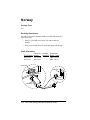
Norway
Country Code
470
Redialing Restrictions
For calls to the same telephone number over the same trunk, the
application must:
• Delay five seconds between the first and second call
attempt.
• Delay sixty seconds between each subsequent call attempt.
Cable Information:
Cable Part
TR114 Model Number
TR114+I2L
TR114+I4L
340-050-02
340-050-01
Quantity
Required
1
1
Connectors:
Board → Wall
DB9 → RJ-11
DB9 → RJ-11
TR114+I4L
Wall Jack
9
6
5
1
Pin 1
Pin 1
RJ-11 Plugs
DB9 Plug
3-28 TR114 ISA Analog International Hardware Guide
Connector Pinouts:
340-050-01:
For TR114+I4L
340-050-02:
For TR114+I2L
DB9
RJ-11
DB9
RJ-11
1 - Red
1 - NL
1 - Red
1 - NL
2 - Red
2 - NL
2 - Red
2 - NL
3 - NC
3 - Red
3 - NC
3 - Red
4 - Red
4 - Green
4 - NC
4 - Green
5 - Red
5 - NL
5 - NC
5 - NL
6 - Green
6 - NL
6 - Green
6 - NL
7 - Green
7 - Green
8 - Green
8 - NC
9 - Green
9 - NC
Country Codes, Redialing Restrictions, Compliance, and Cable
Descriptions
3-29
Singapore
Country Code
650
Redialing Restrictions
For an unsuccessful attempt to dial any telephone number, the
application must:
• Make no more than ten additional call attempts.
• Delay a minimum of sixty seconds between each call
attempt.
Cable Information:
Cable Part
TR114 Model Number
TR114+I4L
340-036-02
Quantity
Required
2
Connectors:
Board → Wall
RJ-45 → RJ-11
TR114+I4L
Wall Jack
Pin 1
Pin 1
RJ-11 Plug
RJ-45 Plug
3-30 TR114 ISA Analog International Hardware Guide
Connector Pinouts:
340-036-02: For TR114+I4L
RJ-45
RJ-11:
Channel A
RJ-11:
Channel B
1 - NC
1 - NL
1 - NL
2 - NC
2 - NC
2 - NC
3 - Yellow
3 - Green
3 - Black
4 - Green
4 - Red
4 - Yellow
5 - Red
5 - NC
5 - NC
6 - Black
6 - NL
6 - NL
7 - NC
8 - NC
Country Codes, Redialing Restrictions, Compliance, and Cable
Descriptions
3-31
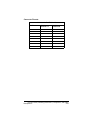
Spain
Country Code
340
Redialing Restrictions
• For transmissions of any one document to any one
telephone number, the application must:
- Make no more than five call attempts in one hour.
- Delay five seconds between the first and second call
attempts.
- Delay one minute between each subsequent call attempt.
• For calls to different telephone numbers over the same
trunk, the application must delay two seconds between
releasing the line after an unsuccessful call attempt and
seizing it for the next call attempt.
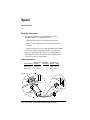
Cable Information:
Cable Part
TR114 Model Number
TR114+I2L
TR114+I4L
340-050-02
340-050-01
Quantity
Required
1
1
Connectors:
Board → Wall
DB9 → RJ-11
DB9 → RJ-11
TR114+I4L
Wall Jack
9
6
5
1
Pin 1
Pin 1
RJ-11 Plugs
DB9 Plug
3-32 TR114 ISA Analog International Hardware Guide
Connector Pinouts:
340-050-01:
For TR114+I4L
340-050-02:
For TR114+I2L
DB9
RJ-11
DB9
RJ-11
1 - Red
1 - NL
1 - Red
1 - NL
2 - Red
2 - NL
2 - Red
2 - NL
3 - NC
3 - Red
3 - NC
3 - Red
4 - Red
4 - Green
4 - NC
4 - Green
5 - Red
5 - NL
5 - NC
5 - NL
6 - Green
6 - NL
6 - Green
6 - NL
7 - Green
7 - Green
8 - Green
8 - NC
9 - Green
9 - NC
Country Codes, Redialing Restrictions, Compliance, and Cable
Descriptions
3-33
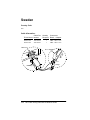
Sweden
Country Code
460
Cable Information:
Cable Part
TR114 Model Number
TR114+I2L
TR114+I4L
340-050-02
340-050-01
Quantity
Required
1
1
Connectors:
Board → Adapter
DB9 → RJ-11 to 4
DB9 → RJ-11 to 4
TR114+I4L
RJ-11 Adapter
9
6
5
1
Pin 1
Pin 1
RJ-11 Plugs
DB9 Plug
3-34 TR114 ISA Analog International Hardware Guide
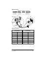
Connector Pinouts:
340-050-01:
For TR114+I4L
340-050-02:
For TR114+I2L
DB9
RJ-11
DB9
RJ-11
1 - Red
1 - NL
1 - Red
1 - NL
2 - Red
2 - NL
2 - Red
2 - NL
3 - NC
3 - Red
3 - NC
3 - Red
4 - Red
4 - Green
4 - NC
4 - Green
5 - Red
5 - NL
5 - NC
5 - NL
6 - Green
6 - NL
6 - Green
6 - NL
7 - Green
7 - Green
8 - Green
8 - NC
9 - Green
9 - NC
Country Codes, Redialing Restrictions, Compliance, and Cable
Descriptions
3-35
Switzerland
Country Code
410
Redialing Restrictions
• For an unsuccessful attempt to dial any telephone number,
the application must:
- Make no more than four call attempts. Each transmission
of dialing information counts as one dial attempt.
- Delay a minimum of thirty seconds between each call
attempt.
- Release the line for a minimum of five seconds before
dialing a different telephone number.
• For a successful dialing to any telephone number, the
application must:
- Prevent automatic dial attempts to the same telephone
number.
- Release the line for a minimum of five seconds before
dialing a different telephone number.
3-36 TR114 ISA Analog International Hardware Guide
Cable Information:
Cable Part
TR114 Model Number
TR114+I2L
TR114+I4L
340-050-02
340-050-01
Quantity
Required
1
1
Connectors:
Board → Wall
DB9 → RJ-11
DB9 → RJ-11
TR114+I4L
Wall Jack
9
6
1
5
Pin 1
Pin 1
RJ-11 Plugs
DB9 Plug
Connector Pinouts:
340-050-01:
For TR114+I4L
340-050-02:
For TR114+I2L
DB9
RJ-11
DB9
RJ-11
1 - Red
1 - NL
1 - Red
1 - NL
2 - Red
2 - NL
2 - Red
2 - NL
3 - NC
3 - Red
3 - NC
3 - Red
4 - Red
4 - Green
4 - NC
4 - Green
5 - Red
5 - NL
5 - NC
5 - NL
6 - Green
6 - NL
6 - Green
6 - NL
7 - Green
7 - Green
8 - Green
8 - NC
9 - Green
9 - NC
Country Codes, Redialing Restrictions, Compliance, and Cable
Descriptions
3-37
United Kingdom
Country Code
440
Note: If the country code in btcall.cfg does not match the
country on the label on the back of the board, calls
can neither be sent or received.
Redialing Restrictions
For transmission of any one document to any one telephone number,
the application must:
• Make no more than sixteen call attempts.
• Delay five seconds between each call attempt.
Cable Information:
TR114 Model
Cable Part
Number
TR114+I1L
TR114+I2L
TR114+I4L
340-064-01
340-050-08
340-050-05
Quantity
Required
1
1
1
Connectors:
Board → Wall
DB9 → 431A UK
DB9 → 431A UK
DB9 → 431A UK
TR114+I4L
9
6
5
1
Pin 1
Pin 1
431A Plugs
DB9 Plug
3-38 TR114 ISA Analog International Hardware Guide
Connector Pinouts:
340-050-05:
For TR114+I4L
340-050-08:
For TR114+I2L
340-064-01:
For TR114+I1L (Ch. 0)
DB9
431 A
DB9
431 A
DB9
431 A
1 - Red
1 - NL
1 - Red
1 - NL
1 - NC
1 - NL
2 - Red
2 - Green
2 - Red
2 - Green
2 - Red
2 - Green
3 - NC
3 - NC
3 - NC
3 - NC
3 - NC
3 - NC
4 - Red
4 - NC
4 - NC
4 - NC
4 - NC
4 - NC
5 - Red
5 - Red
5 - NC
5 - Red
5 - NC
5 - Red
6 - Green
6 - NL
6 - Green
6 - NL
6 - Green
6 - NL
7 - Green
7 - Green
7 - NC
8 - Green
8 - NC
8 - NC
9 - Green
9 - NC
9 - NC
Country Codes, Redialing Restrictions, Compliance, and Cable
Descriptions
3-39
Chapter 4
Testing and Troubleshooting
This chapter explains how to test a TR114 installation using
Brooktrout’s configuration and test software. The test software is
included on diskette with the board; the diskette is labelled “TR
Series Hardware Test”. You can also download a copy from the
Brooktrout web site; see Chapter 5, Contacting Technical Support for
the procedures.
Using the Test Software
In order to test the TR114, the board must be installed in the computer
and connected to active loop-start telephone service. The following
tasks are required to install and use the test software:
• Load the test software
• Change the TR114 configuration, if necessary.
If you installed more than one TR114 or TR series boards,
you must change the configuration file (btdriver.cnf) before
you run the tests.
• Set the country code in the user.cfg file
• Boot the system under DOS
• Test the configuration
• Test each loop-start channel by sending and receiving a fax
4-1
TR114 Test Files
Table 4-1 describes the files included in the test software. The test
files must remain together; do not store them in separate directories.
Table 4-1. TR114 Test Files
File Name
Description
btdriver.bat,
A batch file and DOS TSR that must be installed in
btk1.exe, btk2.exe order to run the faxtest program.
btdriver.cnf
The configuration file that contains the interrupt, the
DMA channel, and the I/O addresses of the TR114
channels in the system. Used by the btdriver.bat file.
country.cfg
Read-only configuration file with country-specific
information.
faxtest.exe
A test program to send and receive facsimiles.
send.fil
A single page Group 3 fax test file; sent by default.
test-164.pex
Test firmware automatically downloaded by the faxtest
program to the TR114.
user.cfg
A user-modifiable configuration file that contains a
number of run-time configuration parameters.
Installing the Test Software
This section explains how to install the TR114 test software. You can
copy the contents of the diskette to the hard drive or run the program
from the diskette.
Note: If you are using OS/2 or Windows NT (with the
NTFS file system), do not use the test program from
a DOS window. Boot from a DOS diskette (not
supplied by Brooktrout) and run the test software
from the diskette drive.
1. Make the directory in which to store the test software (for
example, bfax\faxtest) by typing:
mkdir \bfax\faxtest
2. Make the new directory the current directory:
cd \bfax\faxtest
4-2 TR114 ISA Analog International Hardware Guide
3. Copy the files from the diskette to the current directory:
copy A:*.*
4. If there are other software applications or TSRs for
Brooktrout boards running on the system, create a
temporary autoexec.bat file that does not contain the lines
that run such software.
5. Reboot the system under DOS using the modified
autoexec.bat file.
Remember to restore the original autoexec.bat file when
you finish testing.
Changing the TR114 Configuration
Depending on the number and models of TR114 boards installed and
whether their installation caused any conflicts with other hardware or
software in the system, you may need to edit the btdriver.cnf
configuration file distributed with the test software. You can use any
text editor to change the parameters in this file.
The btdriver.cnf configuration file contains the following
configuration parameter values:
intnum 5
dmachan 1
addrs 264 4
This file is for a single, four-channel TR114 ISA board with the
default configuration. The configuration parameters shown above
indicate that a four-channel TR114 is installed at base address 260
and is using interrupt 5 and DMA channel 1.
For each additional TR114, add another addrs line in the
configuration file. For example, if you installed two TR114
four-channel boards in the system (one at address 260 and the other at
address 280), change the contents of the btdriver.cnf configuration
file as follows:
intnum 5
dmachan 1
addrs 264 4
addrs 284 4
Testing and Troubleshooting
4-3
If you installed one TR114 two-channel board in the system (at
address 260), change the contents of the configuration file as follows:
intnum 5
dmachan 1
addrs 264 2
Setting the Country Code
If you need to change the country code in your application software,
you will also need to change it in the user.cfg file in order to run the
test program. Note that if you are testing the board using the software
from the Brooktrout-supplied diskette, the test file, user.cfg is the
same file as btcall.cfg and will require the same parameter settings
that you make in btcall.cfg.
Testing the Configuration
Test the TR114 configuration using the following procedure.
1. Boot the system to run under DOS.
2. Change to the directory in which you copied the test
software.
3. Execute the btdriver batch file:
btdriver btdriver.cnf
4. Verify that the program displays the same number of
channels you installed and specified in the btdriver.cnf file.
For example, if you have one TR114 four-channel board
installed, you should see the following output:
Total Channels: 4 TR114; 0 Trufax;
0 TR112/TR111MC; 0 TR200
No BRI TR114s found
If you have two TR114 four-channel boards installed in
your system, you should see the following output:
Total Channels: 8 TR114; 0 Trufax;
0 TR112/TR111MC; 0 TR200
No BRI TR114s found
5. If the number of channels is correct, the system initialized
successfully. If it is not correct, refer to the following
checklist for possible solutions.
4-4 TR114 ISA Analog International Hardware Guide
a. Make sure the switches on the address switch (SW1) and
the interrupt jumper are set correctly on the board, and
that they match the parameters in the btdriver.cnf
configuration file.
b. Make sure the I/O address settings do not conflict with
another device in your system. Refer to Appendix B,
Common System Resource Assignments for more
information.
c. If you are installing multiple TR114s, make sure that
each board had a unique base I/O address and that it is
entered in the btdriver.cnf configuration file.
d. Make sure the LEDs (on the TR114 mounting bracket)
flash once when you power up the system. If they fail to
flash, or if they remain on, there may be a problem with
the TR114 or with the computer. To determine where the
problem lies, see the section, Troubleshooting on page
4-7 for help.
Testing the Loop-Start Channels
This section explains how to send and receive faxes with the faxtest
program in order to test the TR114 loop-start channels. In order to run
these tests, the btdriver program must have run successfully and the
TR114 must be connected to the telephone service.
Press Q at any time to quit faxtest.
Faxtest Command Line Options
The following command line options allow you to specify additional
information when sending or receiving a fax when you are running
the faxtest program.
-r
Places the channel in receive mode.
-s <phonenum> Places the channel in send mode and
sends the phone number in
<phonenum>.
Testing and Troubleshooting
4-5
-u
The unit parameter followed by the
number of the channel that you want to
test, e.g, -u 0 specifies channel 0.
#
-v
Turns on verbose output, to capture the
trace data.
-w
Forces the TR114 to wait for a dial tone.
Displaying Command Line Options
You can display the list of command line options by typing:
faxtest
Sending a Test Fax
To test sending a fax, test all TR114 loop-start channels.
To send a fax from any TR114 loop-start channel, follow these steps,
pressing Enter after each entry:
1. Change to the directory where you copied the test software.
2. Execute the faxtest program, where # is the number of the
channel and phonenum is the phone number of the
receiving fax machine:
faxtest -u # -s phonenum
Note: If you install the TR114 on a PBX extension,
you may have to insert a prefix (e.g., 9) in front of
the fax machine’s phone number, for example,
faxtest -u # -s 95551212
3. If the fax transmission is successful, the faxtest program
displays the following message at the end of transmission:
Fax Sent Successfully - Test Completed.
Otherwise, an error message is displayed. Refer to the
section, Troubleshooting on page 4-7 to determine the
cause of the problem.
Receiving a Test Fax
For receiving faxes, you only need to run the faxtest program on
even-numbered channels (including channel 0).
4-6 TR114 ISA Analog International Hardware Guide
To receive a fax, follow these steps, pressing the Enter key after each
entry:
1. Change to the directory where you copied the test software.
2. Execute the faxtest program, where # is the number of the
channel:
faxtest -u # -r
3. From a fax machine, dial the telephone number connected
to the channel you are testing to send it a test fax.
If the fax is received successfully, the faxtest program
displays the following message at the end of reception:
Fax Received Successfully - Test Completed.
Otherwise, an error message is displayed. Refer to the next
section, Troubleshooting, to determine the cause of the
problem.
Troubleshooting
This section describes some errors you may encounter when you run
the test program. Some solutions are also provided for resolving the
problem.
Some Typical Errors
SYMPTOM(S):
LEDs do not flash on power up.
Probable Cause:
There was a self-test failure at power on. The
power supply requirements may be unsuitable.
Solution:
Try installing the board in a different system.
SYMPTOM(S):
Cannot consistently originate and/or answer
calls
Probable Cause:
Country code mismatch
Solution:
Ensure that the country code in the user.cfg file
matches the country specific variant on the
back of the board.
Testing and Troubleshooting
4-7
SYMPTOM(S):
btdriver does not detect all the channels in the
system.
Two channels should be detected for each
two-channel board and four channels for each
four-channel board.
Probable Cause:
Solution:
I/O address conflict with other devices in the
system, possibly other Brooktrout boards.
Ensure the addrs entries in the btdriver
configuration files are 4 hex more than the
switch settings of the hardware.
Use operating system tools (such as
NTdiagnostics), system documentation, or
BIOS configuration, to check for device
conflicts and available I/O addresses.
Remove all Brooktrout boards from the system,
then re-install and test them one at a time.
Remove other boards, such as network
adapters, to check for conflicts.
4-8 TR114 ISA Analog International Hardware Guide
SYMPTOM(S):
btdriver loads successfully but the faxtest
program does not display output after
attempting to reset the channel.
Probable Cause:
Interrupt conflicting with another device,
interrupt jumper wire installed on wrong
number, not set snugly on the pins, or not set
correctly in the btdriver.cnf file.
Solution:
Make sure the interrupt jumper wire is on the
correct pins.
Check that the interrupt pull-up switch (switch
1 on SW1) is set to ON, on only one board in
the system.
Ensure that the intnum parameter in the
btdriver.cnf file matches that of the board.
Use operating system tools (such as
NTdiagnostics), system documentation, or
BIOS configuration, to check for device
conflicts and available interrupts.
Try other jumper settings, even if the interrupt
chosen is expected to be free.
Check the BIOS configuration if one is
available for your system. Many EISA systems
will not allow the interrupt to be used unless it
is configured in the BIOS.
Remove other boards, such as network
adapters, to check for conflicts.
Testing and Troubleshooting
4-9
..
SYMPTOM(S):
Cannot send and/or receive faxes properly;
Fax can be received but is unrecognizable.
Probable Cause:
DMA conflict or mismatch, or a DMA
incompatibility exists with the computer’s
motherboard.
Solution:
To identify if it is a DMA or interrupt issue,
disable DMA by changing the dma parameter
from dma 512 to dma 0 in the user.cfg file.
If it is an interrupt issue, try one of the
following:
• Try other jumper settings, even if the interrupt
chosen is expected to be free.
• Use operating system tools (such as
NTdiagnostics), system documentation, or
BIOS configuration, to check for device
conflicts and available interrupts.
• Check the BIOS configuration if one is
available for your system. Many EISA
systems will not allow the interrupt to be used
unless it is configured in the BIOS.
• Make sure that the interrupt jumper wire is on
the correct pins.
• Check that the interrput pull-up switch
(switch 1 on SW1) is set to ON on only one
board in the system.
• Ensure that the intnum parameter in the
btdriver.cnf file matches that of the board.
• Remove other boards, such as network
adapters, to check for conflicts.
4-10 TR114 ISA Analog International Hardware Guide
Sending the Test Results to a File
You can redirect the output from your fax test to a file. If you need to
contact Brooktrout Technical Support or your reseller to resolve
problems you cannot correct, they will want to examine the test
results to determine the cause of the malfunction.
In the following steps, # is the number of the channel you are testing,
log.txt is the name of the output file, and -v sets verbose mode to
capture the data.
1. On sending a fax, redirect the output from the test program
to a file by typing:
faxtest -u # -v -s phonenum >log.txt
2. On receiving a fax, redirect the output from the test
program to a file by typing:
faxtest -u # -v -r >log.txt
We recommend that you fax or e-mail the test results to Brooktrout
Technical Support or to the reseller from whom you purchased your
TR114 board. For instructions on how to contact or send test results
to Brooktrout Technical Support, see Chapter 5, Contacting
Technical Support.
Rebooting the Operating System
Reboot your system to run under the operating system you normally
use. If your system normally runs under DOS, and you booted your
system with a special autoexec.bat file to run the test software, reboot
your system now using the original autoexec.bat file that contains the
lines that run your fax application software.
You can now configure your fax software and start sending and
receiving faxes with your TR114 ISA board.
Testing and Troubleshooting
4-11
Chapter 5
Contacting Technical
Support
Brooktrout provides technical support for customers who have
purchased their TR114 board directly from Brooktrout Technology,
Inc. If you purchased your TR114 board from a reseller, contact that
reseller for technical support.
In the event of equipment malfunction, Brooktrout Technology, Inc.
or an authorized agent should perform all repairs. The user is
responsible for reporting the need for service to Brooktrout or to one
of its authorized agents.
Getting Technical Support
If you call Brooktrout Technical Support, please be prepared to work
with the support personnel. You may be asked to do several things,
such as taking down your server.
Please have the following information ready:
• The part number (PN) of the TR114 board in question.
Part numbers begin with the digits 802 or 812. The part
number is on the back, or solder-side, of the base board.
• Test results obtained from running the diagnostic software
(refer to the section, Sending the Test Results to a File on
page 4-11 for instructions for creating a file).
Contact the Brooktrout office nearest to you. The numbers are shown
in the following pages.
5-1
Contacting Belgium
• Telephone: +32 2 658 0170
• e-mail: [email protected]
• Fax: +32 2 658 0180
• FTP Site: ftp.brooktrout.com
• Web Site: http://www.brooktrout.com
Contacting Japan
• Telephone: +81 3 5800 9183
• e-mail: [email protected]
• Fax: +81 2 658 0180
• FTP Site: ftp.brooktrout.com
• Web Site: http://www.brooktrout.com
Contacting Singapore
• Telephone: +65 224 4485
• e-mail: [email protected]
• Fax: +65 224 0337
• FTP Site: ftp.brooktrout.com
• Web Site: http://www.brooktrout.com
Contacting USA
• Telephone: +1 781-433-9600
• e-mail: [email protected]
• Fax: +1 781-449-9009
• FTP Site: ftp.brooktrout.com
• Web Site: http://www.brooktrout.com
5-2 TR114 ISA Analog International Hardware Guide
Downloading Software from the FTP
Site
You can download copies of the latest TR114 firmware and the
diagnostic software from the Brooktrout FTP site. Use the following
procedures.
TR114 Firmware
1. Connect to the Brooktrout FTP site by typing the following:
ftp.brooktrout.com
2. Log in as anonymous. Enter your e-mail address as your
password when required.
3. Change to the firmware directory:
cd support/firmware/v18x
where x is the latest revision of the software.
4. In binary mode, transfer the files, v18x.pex, v18x-2m.pex,
and the contents of the csum folder.
Diagnostic Software
1. Connect to the Brooktrout FTP site by typing the following:
ftp.brooktrout.com
2. Select the support directory.
3. Select diag.zip.
Click the appropriate file from the list that is displayed; the software
downloads automatically.
Contacting Technical Support
5-3
Returning a Defective TR114 Board
If you suspect that your TR114 board is malfunctioning, contact
Brooktrout Technology Europe Ltd. or the reseller from whom you
purchased it.
Typically, Brooktrout Technical Support or your reseller will request
that you run diagnostics on the TR114 board to determine whether it
has a hardware defect. (See page 4-11 for running diagnostics and
creating a file from your test output.) If the board has a hardware
defect, you will need to return it for repair to Brooktrout Technology,
Inc. or to the reseller from whom you purchased it.
If you purchased the TR114 board directly from Brooktrout
Technology, Brooktrout Technology Europe Ltd. will issue a Return
Material Authorization (RMA) number for it. If your TR114 board is
no longer under warranty, you must get a Purchase Order Number
before Brooktrout Technology Europe Ltd. will issue you an RMA
number.
When returning a product on RMA to Brooktrout Technology, Inc.,
write the RMA number clearly on the shipping container and send the
container to the following address:
Brooktrout Technology, Inc.
152 Second Avenue
Needham, MA 02494-2722
USA
5-4 TR114 ISA Analog International Hardware Guide
Appendix A
Installing and Testing
Hong Kong DID Service
This appendix explains how to connect and test a TR114 ISA analog
DID board for Hong Kong.
The TR114 ISA analog board is offered in the following
configurations for use for DID telephone service:
TR114+I2C
TR114+I4C
TR114+I2D
TR114+I4D
-
One loop-start and one DID interface
Two loop-start and two DID interfaces
Two DID interfaces
Four DID interfaces
Requirements for DID
To run a Brooktrout TR114 ISA analog board with DID, your system
requires the following:
• DID telephone service
• External -48VDC power supply
You need to purchase a power supply separately from the
TR114. Brooktrout offers a power supply from Computer
Products that is approved for use with the TR114.
DID Telephone Service
DID (Direct Inward Dialing) lines support incoming calls only. More
than one telephone number is assigned to a DID line. DID service
can provide automatic routing of facsimiles to the proper destination
within a multiuser fax system.
A-1
For example, Company ABC is assigned one DID trunk that is
composed of one hundred telephone numbers ranging from 239-9400
to 239-9499. When any one of the numbers in this range is dialed and
the DID line is available, the telephone company transmits the last
few digits (usually 3 or 4) of the dialed number to the TR114. By
detecting these digits, the TR114 can tell which of the hundred
numbers was actually dialed.
If the line is busy, callers to any of the other numbers encounter a
busy signal. Because of this situation, many fax messaging systems
require more than one DID line to which the range of DID telephone
numbers is assigned. The number of lines required depends on the
traffic demands on the system.
Since DID lines are one-way (inward), a two-way fax messaging
system using DID requires one or more loop-start telephone lines for
sending facsimiles.
The TR114+I2C, which contains one loop-start and one DID
interface, or the TR114+I4C, which contains two loop-start and two
DID interfaces, are options for smaller systems that need only one or
two inbound lines and one or two outbound lines.
The TR114+I2D, which contains two DID interfaces, and the
TR114+I4D, which contains four DID interfaces, are intended for
larger systems that employ two or more DID lines and service a large
volume of calls.
DID Operation
When a person or a fax machine dials a number connected to a TR114
DID channel, the board recognizes it as an incoming call. The next
step depends on how the DID line has been configured – with
wink-start (the most common configuration) service, or with
immediate-start service.
On a line configured for wink-start service, the board performs a
“wink” after it recognizes the call; that is, it signals the telco that it is
ready to receive the last few digits of the dialed number. The telco
transmits these digits to the board with DTMF signals (or in some
cases with pulse signals). You must inform the telco of the number of
DID digits you want the them to transmit.
A-2 TR114 ISA Analog International Hardware Guide
When the TR114 board has detected all of the DID digits, it signals
the telco that it has accepted the call. If the board does not detect the
correct number of DID digits, it plays a fast busy signal.
On a line configured for immediate-start service, the board does not
perform a wink. Instead, the telco waits a fixed amount of time before
it sends the DID digits to the board. Then, when it detects or fails to
detect the correct number of DID digits, the board responds the same
as it does when configured for wink-start service.
Installing the TR114 DID Board
To install and connect a TR114 ISA analog DID board, you will need
to perform the following tasks:
• Configure and install the board using the procedures in
Chapter 2, Configuring and Installing the TR114.
• Install a power supply using the procedures in Installing a
Power Supply for DID Service below.
• Connect the cables using the procedures in the section,
Connecting to DID Service on page A-5.
• Ensure that the board is working using the procedures in the
section, Testing the DID Channels on page A-7.
Installing a Power Supply for DID
Service
The TR114 must supply the DID line with continuous -48VDC power;
service can be lost if the telephone company does not detect -48VDC
power on the line. After you install the TR114 board in the computer
and before you connect the telephone lines for DID service, connect a
power supply to the TR114.
You can connect multiple TR114 boards to a single power supply.
However, Brooktrout recommends that each board have its own
power supply so that power is not lost for multiple boards if a single
power supply fails.
Once the DID power supply is installed, leave it on to ensure
continued DID service. You can turn off the computer without
turning off the DID power supply.
Installing and Testing Hong Kong DID Service
A-3
Connecting a Computer Products Universal
Power Supply
The Computer Products universal power supply is shown in
Figure A-1.
Figure A-1. Computer Products Universal Power Supply
Note: The DID power cord supplied with the board will
not be needed when using the power supply; it can
be retained or discarded.
Attach the power supply using the following procedure.
1. Power off the computer.
2. Locate the power supply, the mains cord set, and the DID
adapter cable shown in Figure A-2.
nd
ou
Gr
rs
cto
ne
n
o
rC
pe
m
Ju
Figure A-2. DID Adapter Cable
3. Verify that the mains cord set is compatible with the mains
power socket that will be used with the power supply. If it is
not, contact Brooktrout Technology for the appropriate
cable.
A-4 TR114 ISA Analog International Hardware Guide
4. Ensure that the ground jumper connectors (shown in
Figure A-2) on the DID adapter cable are mated. This
connects the positive side of the DID power supply output to
earth as required by most telecom authorities. If the mains
supply used does not provide a path to earth, a separate
ground will need to be provided to the black lead in the
ground jumper connector.
5. Plug the DID adapter cable into the end of the DC output
cable from the power supply, and plug the mains cord set
into the AC input socket on the power supply.
6. Plug the jack on the other end of the DID power cable into
the DID power connector on the TR114 mounting bracket.
The jack is keyed to ensure proper insertion.
7. Power up the computer.
8. Plug the mains cord set into a grounded wall socket.
If the wall socket is not grounded, use an adapter to ground
the power supply. Be sure to follow the instructions supplied
with the adapter to connect to ground. Alternatively, plug a
separate earth ground into the female side of the ground
jumper connector (attached to the black wire) on the DID
adapter cable (see Figure A-2).
Connecting to DID Service
After you have installed the TR114 in the computer and connected a
DID power supply to the TR114, you can connect the TR114 to DID
telephone service. Table A-1 shows how the TR114 channels
connect to DID telephone service.
Installing and Testing Hong Kong DID Service
A-5
Table A-1. Channel Identification
TR114
Model
Split Cable
Label
Channel
Service Type
I2D
N/A
0
1
DID
DID
I4D
A
0
1
2
3
DID
DID
DID
DID
B
I2C
N/A
0
1
Loop-start
DID
I4C
A
0
1
2
3
Loop-start
Loop-start
DID
DID
B
Connect the TR114 telephone cables using the following procedure:
1. Locate the cables supplied with your TR114 (the wires on
the split cables for the I4C and I4D are labeled A and B).
2. Plug the end with a single RJ-45 plug into the RJ-45 jack on
the TR114 mounting bracket; plug the RJ-11 plugs at the
other end into wall-mounted DID phone jacks.
Do not plug a DID cable into a loop-start
line – this can cause serious damage to
the TR114.
CAUTION
The TR114 DID channels are now connected to the DID lines.
A-6 TR114 ISA Analog International Hardware Guide
Testing the DID Channels
The test software contains DOS programs and files you can use to
ensure that your TR114 is installed correctly and to run diagnostics if
you have a problem. One of these programs, faxtest, is used to send
and receive faxes and verify DID operation. The btdriver program
can be used to identify the boards and channels.
This section explains how to test DID channels with and without
active DID service:
• Testing without active DID service (with a telephone
connected directly to the DID channel) ensures that the
hardware and power supply are functioning properly.
• Testing with DID service ensures that the TR114 DID
parameters are configured correctly in the btdriver.cfg file
and that the TR114 is providing the proper voltage to the
telco and generating the wink signal.
If you need another copy of the test program (diag.exe), see
Chapter 5, Contacting Technical Support for downloading files from
Brooktrout’s FTP site.
To perform the tests, you need access to a fax machine with a
telephone or a standard analog telephone.
Before you run either test, the btdriver program must be successfully
run, and a -48 VDC power source must be connected to the board.
Before you can run the test with active DID service, you must also
activate the DID line, connect the DID channels on the TR114 to the
telephone lines, and make sure the DID-related parameters in the
user.cfg file match the DID service options.
Changing the DID Configuration
You may have to change the DID configuration; this is done in the
user.cfg test configuration file using any text editor. The user.cfg file
is a text file that contains two DID-related parameters, service type
and DID digits. The default value for service type is wink; the
default value for DID digits is 4.
If your DID service is set up for immediate-start operation, change
wink to immediate. Depending on your DID service, you may
also need to change the number of DID digits.
Installing and Testing Hong Kong DID Service
A-7
If you change the user.cfg file so that the tests are performed
correctly, you should make the same changes in the BTCALL.CFG
file, which is the default user-defined configuration file. User.cfg is a
copy of BTCALL.CFG.
Testing DID Channels without Active Service
To test reception on a DID channel without active service, use a
standard analog telephone or a fax machine with a built-in telephone
to run this test for each DID channel.
1. Connect a fax machine with telephone directly to a DID
channel. Use an RJ-11 cable or the split cable supplied with
the TR114 (see Table A-1 for identifying TR114 DID
channels).
2. Change to the directory in which you copied the test
software (in this example, \bfax\faxtest) by typing:
cd \bfax\faxtest
3. Execute the faxtest program by typing:
faxtest -u # -r
where:
-u # Specifies the number of the channel to test, for example,
-u 0 specifies channel 0.
-r
Places the channel in receive mode.
The program displays the following message:
waiting for a call
If this message does not display, refer to the section,
Troubleshooting Your DID Installation on page A-10, for
information on solving problems.
4. Pick up the handset and dial the appropriate number of DID
digits from the fax machine/telephone connected to the DID
channel you are testing.
If the DID digits are detected successfully, the digits are
displayed on the screen, and the TR114 generates a fax
answer tone.
A-8 TR114 ISA Analog International Hardware Guide
If the DID digits do not display or if there is no fax answer
tone, run the faxtest program again and see if you can hear
the DID digits in the telephone receiver as you enter them.
a. If you can hear the digits, check the setup of the user.cfg
configuration file:
- If the DID parameter values are incorrect, change them.
- If the DID parameter values are correct, run the faxtest
program again, and make sure it’s really waiting for a
call.
b. If you cannot hear the digits, the line is not receiving
voltage.
Check the power supply, the power connection, and the
cable to the TR114.
Testing DID Channels with Active Service
To test call reception on any DID channel with active DID service:
1. Connect the DID channel to the DID telephone line. Use an
RJ-11 cable or the split cable supplied with the TR114.
2. Change to the directory in which you copied the test
software (in this example, \bfax\faxtest) by typing:
cd \bfax\faxtest
3. Execute the faxtest program by typing:
faxtest -u # -r
where:
-u # Specifies the number of the channel to test, for example,
-u 0 specifies channel 0.
-r
Places the channel in receive mode.
The program displays the following message:
waiting for a call
If this message fails to display, refer to the Troubleshooting
Your DID Installation, for information on solving problems.
4. Make a call to your DID channel and check to see if you
hear fax tones. If so, the line is working correctly.
Installing and Testing Hong Kong DID Service
A-9
If instead, you hear a fast busy signal, the telephone
company may not have yet activated the line. Check with the
telephone company; if they tell you that the line is activated,
see the next section for more information.
Troubleshooting Your DID Installation
You may encounter errors when you run the faxtest program when
you are connected to DID service. Some possible errors are
explained below, along with some solutions for resolving the
problem. Also see the section on troubleshooting on page 4-7 for
more help.
SYMPTOM(S):
DID line does not work, or there is a fast-busy
signal.
Probable Causes: DID service may not be activated, or;
The number of DID digits may not be set
correctly in the user.cfg file, or;
There is a polarity problem; the telephone wiring
may be reversed. That is, although the output of
the TR114 has the correct polarity across the
telephone line’s two wires, a wiring reversal could
exist elsewhere in the building.
Solution: Verify that the number of DID digits is set
correctly in the user.cfg file.
Make sure that DID service is active by testing
the line using the procedures in the section,
Testing DID Channels without Active Service on
page A-8.
If the telephone test works, but you still have
problems with your DID line, make sure the
telephone wiring is not reversed.
A-10 TR114 ISA Analog International Hardware Guide
SYMPTOM(S):
Noise on a DID trunk when you make a call to it.
Probable Cause: Grounding problem.
Solution: OPen the ground jumper on the DID adapter cable
(see Figure A-2).
Contact Brooktrout Technical Support. See
Chapter 5, Contacting Technical Support.
SYMPTOM(S):
DID line was working but now it stops working.
Probable Cause: Power from the DID power supply has been
interrupted, or;
Service may have been discontinued by the telco.
Solution: Make sure the DID line is connected to the TR114
and that the board is receiving -48VDC power
from the DID power supply.
Call one of the telephone numbers in your block
of DID numbers. If a busy signal sounds
immediately, the service has probably been
disconnected by the telco.
Installing and Testing Hong Kong DID Service
A-11
Appendix B
Common System Resource
Assignments
Addresses Used by Other Devices
In addition to the TR114, other boards, hardware devices, and
software commonly use particular addresses. Table B-1 lists some of
the functions that systems may assign to particular addresses.
Table B-1. System Address Assignments
Address
Function
000-01F
DMA controller 1
020-03F
Interrupt controller 1
040-05F
Timer
060-06F
Keyboard controller
070-07F
Real time clock
080-09F
DMA page memory
0A0-0BF
Interrupt controller 2
0C0-0DF
DMA controller 2
0E8
Shadow RAM and cache control bit
0F0-0F1
Numeric processor extension
0F8-0FF
Numeric processor extension
1F0-1F8
Fixed disk
200-207
Game I/O
278-27F
Parallel printer port 2
2F8-2FF
Serial port 2
B-1
Table B-1. System Address Assignments (Continued)
Address
Function
300-31F
Prototype board
360-36F
Reserved
378-37F
Parallel printer port 1
380-38F
SDLC, bisynchronous 2
3A0-3AF
Bisynchronous 1
3B0-3BF
Monochrome display and printer adapter
3C0-3CF
Reserved
3D0-3DF
Color/graphics monitor adapter
3F0-3F7
Diskette controller
3F8-3FF
Serial port 1
Hardware Interrupts Used by Other
Functions
Table B-2 lists some of the functions that computers sometimes
assign to particular interrupts.
Table B-2. Hardware Interrupt Assignments
Interrupt
Function
3
Serial port 2
4
Serial port 1
5
Sound card, parallel port 2
6
Diskette controller
7
Parallel port 1
9
Software redirect to interrupt 2
B-2 TR114 ISA Analog International Hardware Guide
Table B-2. Hardware Interrupt Assignments (Continued)
Interrupt
Function
10
Unassigned
11
Unassigned
12
Unassigned
14
Fixed disk controller
15
Unassigned
DMA Channels Used by Other Functions
Table B-3 lists some of the functions that systems commonly assign
to DMA channels.
Table B-3. System DMA Channel Assignments
DMA Channel
Function
0
Unassigned
1
SDLC
2
Diskette (IBM PC)
3
Unassigned
4
Cascade for CTRL 1
5
Unassigned
6
Unassigned
7
Unassigned
Common System Resource Assignments
B-3
Index
A
C
Address, setting 2-4
addresses
see also base address
Addresses required, I/O 2-4
Addresses, switch settings
2-6
Addresses, switch settings for
recommended 2-5
Australia
cable information 3-2
country code 3-2
pinouts 3-3
cabling requirements
see country where used
Changing the default settings
2-4
configuration files
BTCALL.CFG file 4-4
Configuration settings, default
2-4
Configuring the board 2-3
connecting to DID service
A-5
connecting to loop-start
service 2-10
country code 2-13
setting 2-13, 4-4
CTR21
cable information 3-7
compliance regulations
3-6
country code 3-6
pinouts 3-7
redialing restrictions 3-6
B
base address B-1
default 4-3
Base address, setting 2-4
Base address, switch settings
2-6
Base addresses, switch settings
for recommended 2-5
Board, configuring 2-3
Brooktrout software, installing
2-11
BTCALL.CFG file 2-13
D
data transfer methods 2-12
Index-1
Default configuration settings
2-4
Default settings, changing 2-4
default TR114 configuration
4-3
defective board, returning 5-4
Denmark
cable information 3-4
country code 3-4
pinouts 3-5
redialling restrictions 3-4
device conflicts B-1
DID
changing configuration
A-7
connecting power supply
A-3
connecting service A-5
testing service A-9
DMA
channels used by other
functions B-3
default 4-3
setting 2-12
pinouts 3-7
redialing restrictions 3-6
F
faxtest
command line options
4-5, 4-6
firmware
obtaining updates 1-3
France
cable information 3-9
country code 3-8
pinouts 3-9
redialling restrictions 3-8
G
Germany
cable information 3-10
country code 3-10
pinouts 3-11
redialling restrictions
3-10
E
H
EC
Hardware interrupt, setting
2-7
Hong Kong
cable information 3-12
compliance regulations
3-12
country code 3-12
pinouts 3-13
redialling restrictions
3-12
cable information 3-7
compliance regulations
3-6
country code 3-6
pinouts 3-7
redialing restrictions 3-6
EISA, using 1-3, 2-8
European community
cable information 3-7
compliance regulations
3-6
country code 3-6
Index-2
TR114 ISA Analog International Hardware Guide
I
I/O addresses required 2-4
I/O addresses, switch settings
for recommended 2-5
Installing software 2-11
Installing your lan fax
software 2-11
Interrupt, setting 2-7
interrupts used by other
functions B-2
Ireland
cable information 3-14
country code 3-14
pinouts 3-15
redialling restrictions
3-14
Italy
cable information 3-16
country code 3-16
pinouts 3-17
redialling restrictions
3-16
J
Japan
cable information 3-18,
3-19
compliance regulations
3-18
country code 3-18
pinouts 3-19
redialling restrictions
3-18
L
LEDs
monitoring 2-3
loop-start service 2-10
connecting 2-10
ordering 1-4
testing 4-6
M
Malaysia
cable information 3-20
country code 3-20
pinouts 3-21
redialling restrictions
3-20
N
Netherlands
cable information 3-22
country code 3-22
pinouts 3-23
redialling restrictions
3-22
New Zealand
cable information 3-24
compliance regulations
3-24
country code 3-24
pinouts 3-26
redialling restrictions
3-24
Norway
cable information 3-28
country code 3-28
pinouts 3-29
redialling restrictions
3-28
Lan fax software, installing
2-11
Index-3
O
operating requirements 1-4
operating systems supported
1-2
P
power supply for DID A-3
R
Recommended base I/O
addresses, switch settings
2-5
returning defective board 5-4
S
Setting the base address 2-4
Setting the hardware interrupt
2-7
Settings for recommended
base i/o address switches
2-5
Settings for the base address
switches 2-6
Settings, Changing the Default
2-4
Settings, Default
Configuration 2-4
Singapore
cable information 3-30
country code 3-30
pinouts 3-31
redialling restrictions
3-30
software
configuring 2-11
Index-4
downloading from FTP
5-3
Software, installing 2-11
Software, installing LANfax
2-11
Spain
cable information 3-32
country code 3-32
pinouts 3-32
redialling restrictions
3-32
Sweden
cable information 3-34
country code 3-34
pinouts 3-35
Switch settings for
recommended base i/o
addresses 2-5
Switch settings for the base
address 2-6
Switzerland
cable information 3-36,
3-37
country code 3-36
pinouts 3-37
redialling restrictions
3-36
system requirements 1-3
system resource assignments
B-1
T
technical support 5-1
contacting Belgium 5-2
contacting Japan 5-2
contacting Singapore 5-2
contacting USA 5-2
test files 4-2
user.cfg 4-2
TR114 ISA Analog International Hardware Guide
test results
creating a file from 4-11
test software
about 4-1
downloading from FTP
5-3
installing 4-2
running from DOS 4-2
testing DID A-7
with active service A-9
without active phone
service A-8
testing loop-start 4-5, 4-6
receiving a test fax 4-6
sending a test fax 4-6
troubleshooting
DID A-10
loop-start 4-7
U
United Kingdom
cable information 3-38
country code 3-38
pinouts 3-39
redialling restrictions
3-38
Index-5