1
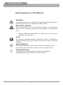
X
With transport option
Supplier: This manual must be given to the user/care giver of this
wheelchair.
Rider: Before using this wheelchair, read this entire manual and save for future reference.
Centre of Gravity
Tilt in Space Wheelchair
Sta n d a r d , E x t r a Wide
& P aediatric
User Guide
Part No. 1536525 Issue 05
11-5-2010
Table of Contents
Useful Symbols In This Guide
Introduction
Warranty Terms & Conditions
Limitation of Liability
Intended Use
2
3
4
5
6
Safety & Operating Limits
Weight Limit
Reaching For An Object From
A Wheelchair
Transferring To Another Seat
Tilting The Chair
Kerbs, Or Obstacles 30mm
To 50mm High
Steps, Stairs Or Obstacles Over
50mm High
Upward & Downward Slopes
(Operating Limits)
Summary Of Safety Instructions
7-16
7
General Descriptions
CGX™ Features
Use
Unfolding the CGX™ Folding the CGX™
Main Frame
Angle Adjustable Footplates
Individual Flip Up Footplates
Quick Release Axle
Flip Back Arm
Locking Flip Back Arm
Castors
Wheel Locks
16
17
18-24
18
19
20
21-22
22
22
23
23
23
23-24
Adjustments
Folding Back
Backpost Angle And Depth
Adjustment
Flip Arm/Locking Arm
Castor Fork Adjustment
Wheel Lock Adjustment
Anti Tip Lever Adjustment
24-26
24
Tilting The CGX™
26
Changing Frame And Seat
Widths
27
Cleaning And Maintenance
27 Storage
27
Troubleshooting - Mechanical
28-29
Transportation
30-31
Product End Of Life
31
Contacting INVACARE
32-33
7-8
9-10
11
12
13
14
15
24
25
25
25
26
1
Useful Symbols
Useful Symbols In This Manual
WARNING!
This symbol warns you of danger! Always follow the instructions to
avoid injury to the user or damage to the product!
EXPLOSION HAZARD!
This symbol warns you of an explosion hazard, an example of
which can be caused by excessive tyre pressure in a pneumatic
tyre!
•
Always follow the instructions to avoid injury to the user or
damage to the product.
NOTE:
This symbol identifies general information which is intended to
simplify working with your product and which refers to special
functions.
REQUIREMENTS:
This symbol identifies a list of various tools, components and
items which you will need in order to carry out certain work.
TRANSPORTATION:
This symbol identifies important information relevant to
transporting your wheelchair in a motor vehicle.
2
Introduction
Introduction
Thank you for purchasing your Freedom Designs, Inc. CGX™
wheelchair. The CGX™ combines state-of-the-art technology with
durablility and function to meet all of your changing needs. This
operating manual will provide you with a detailed guide for proper use as
well as instructions on the care of your new CGX™ wheelchair. Please
follow the instructions carefully, paying special attention to the ‘Safety
Precaution’ section.
It is important that you read the entire operating manual before operating
the CGX™. After consulting your operating manual, if you have further
questions, please contact one of our authorised dealers.
Note for Customers
INVACARE provides a wide range of wheelchairs to meet the
requirements of customers. However, the decision on the type of model
to be prescribed rests exlusively with experienced advisors.
INVACARE or its appointed representative shall not be held responsible
if a wheelchair is used that is unsuitable for the user’s level of disability,
if the wheelchair itself is incorrectly used or if a problem arises due to
poor maintenance.
The information set out in this manual may be modified without prior
notice. This manual contains copyright information. All rights are
reserved. No part of this document may be photocopied or reproduced
without prior written agreement from INVACARE or its appointed
representative.
This manual gives details of all the options of the CGX™
wheelchair. It describes the options, operation and adjustments
that mey be required. However, your INVACARE retailer will be
able to give you further information and demonstration.
3
Warranty Terms &
Conditions
Warranty Terms & Conditions
Standard INVACARE Terms
This is to certify that your wheelchair is warranted by INVACARE Ltd. for a
period of 1 year for parts, 2 years for hardware and frames.
1. Only INVACARE chairs purchased at full price are warranted against
defective workmanship and materials.
2. If a defect or fault is discovered the INVACARE dealer from whom the wheelchair was obtained should be notified immediately.
3. The manufacturer will not accept responsibility for damage caused by misuse or non-observance of the instructions set out in the user manual.
4. During the period of the warranty any parts that have become
defective, due to faulty workmanship or materials, will be renewed or repaired without charge by the INVACARE dealer.
5. The warranty will be invalid should any unauthorised alteration be made to the equipment.
6. The purchaser’s statutory rights under the Consumer Protection Act are not affected.
4
Limitation of Liability
Limitation of Liability
This warranty does not extend to the consequential costs from fault
clearance, in particular freight and travel costs, loss of earnings,
expenses, etc.
•
Natural wear and tear.
•
Inappropriate or incorrect use.
•
Defective assembly or setting-up by the purchaser or third parties.
•
Defective or neglectful treatment.
•
Use of unsuitable spares.
5
Intended Use
Intended Use
The CGX™ manual wheelchair has been designed to provide mobility and
comfort for persons with impaired mobility.
The wheelchair has been designed to be used by a seated user with a carer/
attendant in both indoor and outdoor environments.
The wheelchair has, in its standard format, been designed to accomodate
users who weigh up to a maximum weight of 90kg on a chair width from 10” to
18”, and 136kg on a chair width from 18” to 22”, have all limbs intact and have
sufficent upper body strength to maintain a safe position within the wheelchair
without the addition of supporting aids.
Adaptations from the standard wheelchair format are available to
accommodate users who do not meet the above criteria but these will only be
considered after a suitable risk assessment has been carried out by the product
prescriber. For example, a user with either a full or partial amputation or other
condition, which affects the natural centre of gravity will need to have a stability
evaluation to minimize the risk of inadvertent tipping.
The wheelchair should only be used in accordance with the safety advice given
within this user guide. Failure to follow the recommended advice within this user
guide could lead to personal injury.
No claims are made that the product will medically improve the circumstances
or condition of the user.
6
Safety & Operating
Limits
Safety & Operating Limits
Stability and Equilibrium
To ensure that the wheelchair remains stable and is manipulated correctly,
you must always maintain good equilibrium. Many actions cause the user
of a wheelchair to reach out, lean over or move about within the wheelchair
and outside it. These actions will change your centre of gravity and weight
distribution of the wheelchair. Your wheelchair has been designed to remain
stable for normal everyday use if it is used correctly taking the precautions
recommended in this manual.
Weight Limit
The maximum user weight limit is 90 kg on a chair width from 10” to 18”, and
163kg on a chair width from 18” to 22”.
However, the wheelchair user’s level of activity is important. For example, an
active user weighing 75kg may subject the wheelchair to more stress than
a less active user weighing 114kg. We recommend very active wheelchair
users to choose an appropriate design of wheelchair. Your INVACARE approved
distributor will advise you on the best model.
Reaching For An Object From A Wheelchair
The limitations on reaching out from a wheelchair shown in Figure 1 have been
produced using a representative sample of wheelchair users. Only the arms
should extend beyond the seat of the wheelchair. For safety reasons, the body
and head should remain within the wheelbase.
Position the castors to give the longest possible wheelbase (Figure 2). Lock the
manual brakes on the rear wheels.
7
Safety & Operating
Limits
Leaning Forwards
(Figures 3, 4, 5)
Move the wheelchair as close as possible to the object you wish to reach. Only
reach out for objects that are within arm’s length in a normal sitting position.
Leaning Backwards
(Figures 6, 7)
Move the wheelchair as close as possible to the object you wish to reach. Only
lean back for objects that are within arm’s length in a normal sitting position.
8
!
Safety & Operating
Limits
!
Transferring To Other Seats
Leaning To One Side
(Figure 8)
This is a dangerous manoeuvre as it is easy to tip sideways.
To move up to an object and lean over, you must use the castors as a means of
keeping the wheelchair stable and balanced.
For your safety, it is essential to be in the correct position.
Do not try to pick something up from the floor if this would upset your balance.
It is possible to move from and to a manually propelled chair if the
following guidelines are followed. INVACARE does not reccomend any particular
method for transferring: This is the responsibility of a medical advisor who should
consider your level of disablity and type of wheelchair. When transferring, either
to get out of or return to your wheelchair, make sure that the gap between the
two seats is as small as possible.
(Figures 9, 10)
9
!
Safety & Operating
Limits
!
When transferring, either to get out of or return to your wheelchair, make sure
that the manual brakes on the rear wheels are on to prevent the wheels moving
(Figure 11).
Turn both castors towards the seat to which you wish to move. Lift up the
footplates (Figure 12).
Do not stand on the footplates.
If possible, swing the legrest hangers out to the side to clear the passage
(Figure 13).
If possible, flip up the armrests on the side between the wheelchair and the
other seat (Figure 14).
Note: Never stand on the footplates (Figure 15).
10
!
Safety & Operating
Limits
!
Tilting The Wheelchair
To tilt the wheelchair (Figure 16), a second person should grip the handle
firmly. Warn the user of the wheelchair before tilting it and remind him/her
to lean backwards. Check that the user’s feet and hands are clear of all the
wheels. Push smoothly until the wheelchair is at the point of equilibrium. At this
stage, the helper will feel a difference in weight distribution. Turn the wheelchair
in the direction required and negotiate the obstacle.
Lower the front of the wheelchair smoothly, holding the handles firmly. Do not
lower the wheelchair suddenly for the last few centimeters before returning to
the normal position, this may cause discomfort.
11
!
Safety & Operating
Limits
!
Kerbs, Or Obstacles 30mm To 50mm High
Method 1 - Negotiating the obstacle forwards
(Figure 17)
The helper should tilt the wheelchair until the castors have passed over the
kerb. Move the wheelchair forwards and lower the castors gently onto the
pavement. Push the wheelchair until the rear wheels touch the kerb. Lift and
push until the rear wheels have mounted the kerb. Do not just lift by the handles
on the backrest.
Method 2 - Negotiating the obstacle backwards
(Figure 18)
The helper should stand on the pavement and turn the wheelchair until the
rear wheels are against the kerb. Tilt the wheelchair backwards to the point of
equilibrium and, in a continuous movement, pull the wheelchair until the rear
wheels mount the kerb and pass onto the pavement. Do not lower the castors
to the ground until you have pulled the rest of the wheelchair sufficiently far to
clear the kerb.
Note: Folding backs should always be checked to ensure they are engaged.
12
!
Safety & Operating
Limits
!
Steps, Stairs Or Obstacles Over 50mm High
We recommend that you take very great care when taking a wheelchair up or
down stairs. Two people are required for this.
ADVICE TO SECOND OR THIRD PERSONS:
Make sure that you get hold of fixed, non-removable parts only!
Using the following procedure for going upstairs (Figure 19): Tilt the
wheelchair to its point of equilibrium. One helper (at the back) holds the
wheelchair up against the first step, gripping the handles firmly to lift. The
second helper, holding a firmly fixed part of the front frame, lifts the wheelchair
above the stairs and holds it while the first helper places one foot on the
following step and repeats the operation. The wheelchair must not be lowered
until the last step has been negotiated and until the chair is clear of the stairs.
Escalators
Do not use an escalator when moving a wheelchair from one floor to another.
This might cause serious injury.
13
!
Safety & Operating
Limits
!
Upward & Downward Slopes (Operating Limits)
Do not attempt to go up or down slopes greater than 10% without assistance
(Figure 20).
Always go straight up and down slopes otherwise the wheelchair might overturn
(Figure 21).
14
Safety & Operating
Limits
Summary Of Safety Instructions
Summary of instructions for use for improved safety:
•
•
•
•
•
•
•
•
•
•
•
•
•
•
User weight limit (including accessories): 90kg on a chair width from 10”
to 18”, and 136kg on a chair width from 18” to 22”.
Do not try to reach objects if you have to move forward on the seat.
Do not try to reach objects on the ground if you have to lean down beyond
the safety limits.
Do not lean too far back to reach objects behind you: you may tip over.
Do not move your weight, or your sitting position in the direction in which
you wish to go: you may tip over.
Always apply both manual brakes before trying to get out of or back into
the wheelchair.
The manual brakes are not designed for slowing you down.
Do not try to stop a moving wheelchair using the manual brakes.
Do not use an escalator for moving a wheelchair from one floor to another.
(This may cause serious injury).
Do not use your wheelchair if the tyres are not inflated to the correct
pressure shown on the side.
Do not over-inflate the tyres. Failure to comply with these instructions
may cause the tyre to burst and cause bodily injury.
Carry out the regular checks recommended in this guide and by your
INVACARE approved retailer.
Use your wheelchair with respect for other people.
Do not use your wheelchair as a transport seat in a vehicle. unless it is
not practical for the user to be transferred (Refer to page 31 - Transport).
15
General Descriptions
General Descriptions
Each wheelchair is specially designed to meet the requirements of its user. This
manual describes how to adjust the chairs in this range, enabling you to find out
how to adjust the wheelchair to suit your needs.
General Descriptions
Your wheelchair has a number of main parts which will be mentioned
throughout this manual. These parts are described below.
Support is provided by the backrest, seat and armrests.
The chassis comprises of the side frames and cross brace. This is the
essential supporting framework of the wheelchair on which all the other parts
are mounted.
The front castors comprise of the fork and wheels. The front wheels provide
contact with the ground and the rotating forks steer the chair.
Manual brake - The manual brake is used to park the wheelchair.
Swing away footrest support and leg rest - These are connected to the
chassis and can be swung away to make transfer easier to and from the
wheelchair.
The footplate assembly comprises of the adjustable tube and foot plate.
These support your feet.
The heel support strap or calf support strap. These two straps support your
feet or legs in the best position.
These parts are illustrated on the following page.
16
Features
Freedom CGX TM
9
8
3
5
4
2
12
6
2
10
1
14
13
1. Base Frame
8. Seating
2. Seat Frame
9. Footrest Assembly
3. Backpost
10. Tilt Mechanism
4. Backpost Pivot Plate
11. Anti Tip Lever
5. Backpost Trigger Mechanism
12. Rear Wheel
6
13. Quick Release Axle
Castor Wheel
7. Castor Fork
14. Wheel lock
17
11
Unfolding the Freedom CGX TM
For ease of transporting and lifting, the
chair back can easily be unfolded and
folded.
Always engage the wheel locks by pushing
forward or pulling back on the levers before
unfolding the chair.
1.
Place wheels on quick release axles
and push into axle receiver on frame
until quick release push button “pops
out” and wheels are secure.
2. Set the wheel lock on each side.
3.
Unfolding the back assembly is
accomplished by grasping the push
handles or straight back posts and pulling them to an upright position where they will lock into place.
4. Push the flip back armrests down to
the flat position
18
Folding the Freedom CGX TM
1. Set wheel locks.
2. Flip back the armrests to the upright
position.
3. Pull up on the trigger mechanism for
the backposts and push the backposts
to the flat position over the seat rails.
19
Main Frame
Anti-Tip Device
Flip-up, removable anti-tip levers come
standard on the CGX™.
The anti-tip levers are preset at the factory.
The anti-tips may be adjusted vertically
(see “Anti-Tip Adjustment”, Page 26).
They can also be flipped up out of the way
or removed.
To flip the anti-tip levers up, push in on
the button shown at left. Rotate the lever
inward and upward. The lever will snap
into place in the upward position.
Reverse procedure to place the anti-tips in
the lowered position for use.
To remove the anti-tip levers, push in on
the button at the top of the bend and pull
backward. The anti-tip will slide free of the
frame.
Warning:
Under normal use, anti-tip devices will
prevent the wheelchair from tipping
over backward. Anti-tip devices are to
stay on the chair, in the lower position
shown, when in use and should not be
altered or disabled.
Wheels and Tyres
The CGX™
wheelchair offers the
following tyre options:
12”, 16” and 18” (check prescription form
for options).
Wheels may be removed from the chair
by releasing the quick release axles. (See
quick release axles—Page 22)
Check pneumatic tyres weekly for proper
inflation level listed on the tyre sidewall.
For wheel lock effectiveness, proper tyre
inflation must be maintained.
No-flat inserts are available for the pneumatic
mag wheels.
20
Main Frame
Angle Adjustable Footboard
1. To attach the footboard to the frame, place
the footboard clamps on the frame. Set the clamps at the desired height. Insert the receiver into the clamps and tighten the two
(2) hex head screws on each side.
2. To remove the footboard for transfer, unscrew
the knob assemblies underneath the receivers.
Lift the footboard upward, out of the receivers.
3. To attach the footboard after transfer, align
the footboard fittings into the receivers. Turn the knobs on each side to tighten.
4.
To change the angle of the footboard, use an
allen key and loosen the flat head screws on the top of the footboard. When the desired angle or depth is reached, tighten both screws.
21
Main Frame
Angle Adjustable Footboard…….
5.
To change the height of the footboard on the frame, loosen the two (2) hex head screws on footboard frame clamps. Set the desired
height and tighten.
! Warning: !
In all footplate and hanger adjustments, be
sure that all screws are tightened securely
for your safety.
Individual Flip Up Footplates
Adjustment of the individual flip-up footplates
are as follows:
1. The individual footplates easily flip by lifting
from underneath the footplate to flip up or push down on the footplate to flip down.
To adjust the height of the footplate :
Steps 1 & 2
Step 3
2.
Remove the hex head screws on the side of the hanger. Seat the footplate at the desired height. Insert the screws through the corresponding holes in the hanger tube and tighten.
3.
To adjust the angle of the flip-up footplate,
loosen the lock nuts under the footplate. Set the foot plate at the desired angle and re-tighten nuts.
Quick Release Axle
The CGX™ is equipped with double lock
quick release axles that release with the push
of a button. This double lock quick release
mechanism allows the large drive wheels to be
easily removed for transportation or storage.
To remove the rear wheel:
1. Unlock the wheel lock.
2. Grasp the frame with one hand.
3. With the other hand, squeeze the quick release button.
4. The wheel will then pull off easily.
22
Main Frame
! Warning: !
The axle is not properly locked until the
outside quick release button pops out to its
fully extended position.
Flip Back Arm
The CGX™ is shipped with flip back armrest
as standard equipment. The flip back armrests
are non removable and are available in either
locking or non-locking.
Locking Flip Back Arm
To flip the arm back, push the trigger mechanism
forward as shown and lift arm upward.
Castors
The CGX™ is shipped with 76mm (3”), 102mm
(5”), 152mm (6”), or 178mm (7”) polyurethane
castors with castor forks or a variety of 127mm
(5”) or 152mm (6”) wheels.
Wheel Locks
The CGX™ comes standard with push or pull to
lock wheel locks or hub locks.
Push or Pull to Lock Wheel Locks
To lock wheels in place:
1. Grasp the lever of the wheel lock with your hand.
2. Push lever forward (push to lock) or pull lever back (pull to lock) to engage the wheel lock. Reverse procedure to release the lock.
23
Adjustments
Caution:
Always set the wheel locks when entering
or leaving the wheelchair. Wheel locks are
not designed to slow the wheelchair down
when it is moving. Wheel locks hold the
wheelchair in place when it is at a complete
stop.
Wheel Lock Options
The CGX™ also offers the option of wheel lock
extensions.
Adjustments
Folding Back
Pull Up
The CGX™ comes standard with a folding
back.
1. To fold the back down, pull upward on the
trigger while pushing backposts forward
toward seat.
2. To place the backpost to the upright position,
pull backposts up until trigger snaps into
place.
Note: The backposts fold down completely
when using a solid seat and back. When using
a sling seat and back the backposts will only
fold partially.
Backpost Angle Adjustment
The angle and depth of the backposts may
be adjusted independently. To adjust the back
angle, remove the top screw (A). Tilt the back
to the desired angle, aligning holes in the back
hinge with threaded holes in back mount bracket.
Re-install screw and tighten securely.
A
Backpost Depth Adjustment
B
Remove (2) screws, washers and nuts (B).
Slide back hinge assembly to the new position,
aligning holes in mount bracket with holes in
frame tube. Re-install hardware and tighten
securely.
24
Adjustments
Flip Arm / Locking Arm
To adjust height of armrests, loosen and
remove the bolts and nuts holding the arm
to the backpost tube. Align holes in arm with
holes in backpost tube at desired height.
Re-assemble with bolts and nuts.
Castor Fork Adjustment
Interchanging castors can easily be done with
dual hole castor forks. Currently, 3”, 4” 5”,
6” & 7” castors are available for use (check
prescription form for options). To adjust, loosen
the bolt and remove the castor. Change the
castor and/or position the castor upward or
downward in pre-drilled holes on the castor
fork. Replace the bolt and tighten securely.
Note: When changing the size of the
castor wheel, it will also be necessary to change
the size of the rear wheel in order to keep the
wheelchair frame parallel with the floor.
Wheel Lock Adjustment
When the rear wheel is repositioned, it is important
that the wheel lock is readjusted also.
1. Adjustment can be made by loosening the
1/4-20 x 1” (25.4mm) button head screws
and sliding the wheel lock assembly along the
frame tubing so that the wheel lock contacts
the tyre in the locked position. Continue to
adjust until the knurled grip handle
embeds into the tyre approximately 6.35mm (1/4”) when in the locked position.
Tighten the screw until wheel lock is snug
to frame tube.
Warning:
Wheel locks are not designed to slow the
chair down when it is moving. When the
chair is stopped, engaging properly adjusted
wheel locks will prevent the Drive wheels
from turning.
25
Adjustments
Anti-tip Lever Adjustment
1. Remove the screw, nut and washers that
attach the roller assembly to the lever.
2. Align holes in roller assembly with holes in lever at desired height (recommended at 38.1mm (1-1/2”) to 50.8mm (2”) off of the
ground).
3. Re-install screw, washers and nut—tighten securely.
! Warning: !
Under normal use, anti-tip devices will
prevent the wheelchair from tipping over
backward. Anti-tip devices are to stay on
the chair in the lowered position, at all times
when in use and should not be altered or
disabled.
Tilting the Freedom CGX™
With the chair on a level surface:
1. Set the wheel locks.
2. Hold the handgrips with both hands.
3. Press down and hold the foot tilt lever with your right foot.
4. Push the back handles forward for less tilt or pull rearward for greater posterior tilt.
5. When the desired tilt is achieved, lift up on your foot to engage the tilt lock mechanism.
6. Set the lockout for the foot tilt lever after the
desired tilt angle has been achieved.
! Warning: !
The locking pin must be installed whenever
the chair is in motion.
26
Adjustments
Changing Frame and Seat Width
The seat and frame can be widened in
25.4mm (1”) increments. The frame can be
widened independently to allow for additional
lateral stability.
To widen the frame:
Remove the screws (x 6) located at the lower
arrows (shown at left) under the frame cross
members on each side. Slide the frame out to
desired width. Align holes in cross members
with holes in telescoping frame tubes. Re-install
the screws and tighten securely.
To widen the seat and back:
Remove the (x 4) screws at the two (2) center
arrows on underside of each side of the seat
and the one (1) screw on the back spreader
bar at the top arrow (shown at right). Slide the
frames out to desired width, align holes and
re-install screws. Tighten securely.
Cleaning
It is important for optimum performance to clean and maintain your CGX™. We
recommend that the frame finish be cleaned with mild soap and water.
In order to operate the CGX™ properly and safely, routine maintenance will extend the
life and efficiency of your wheelchair.
Safety Inspection Checklist
Follow these maintenance procedures for optimum performance of your CGX™
wheelchair:
1. Check to see that the wheelchair rolls straight.
2. Tyres: Check for flat spots, wear and proper inflation.
3. Wheel lock:
a.
Check to see that the locks engage easily.
b.
Check that the locks are free of wear
c.
Check to see that the locks do not interfere with the tyres when rolling.
4. Ensure that all fasteners are secure.
5. Castors: Inspect axle for proper tension. Spin the castor. The castor should spin
freely and come to a gradual stop.
Storage
The CGX™ folds down to a small unit and the rear wheels may be removed. We
suggest when storing the wheelchair, that it be stored in an indoor, cool and dry area.
27
Trouble Shooting
A list of authorised repair facilities may be obtained from:
Invacare UK Ltd.
Pencoed Technology Park
Pencoed
Bridgend
CF35 5HZ
Tel: 01656 776222
Fax: 01656 776220
E Mail: [email protected]
Invacare Ireland
Unit 5, Seatown Business Campus
Seatown Road
Swords
County Dublin
Ireland
Tel: + 353 1 8107084
Fax: + 353 1 8107085
E Mail: [email protected]
Web: www.invacare.ie
Trouble Shooting - Mechanical
Initial adjustments should be made to suit personal body structure/user
capability and preference. Thereafter, follow these maintenance procedures:
Chair Veers
Left/Right
Sluggish Turn/
Performance
Castors
“flutter”
X
X
X
X
X
X
Squeaks &
Rattles
If pneumatic, check tyres for
correct and equal pressure
X
Looseness in Chair
Solutions
Chair “3 Wheels”
X
Check for loose stem nuts/bolts
X
Check that both castors contact
ground at the same time
Solutions
If pneumatic, check tyres for correct and
equal pressure
X
X
Check for loose stem nuts/bolts
28
Trouble Shooting
Checking The General Condition
For maintenance operations, consult your distributor who has all the necessary
information.
Ask your distributor to annually inspect your wheelchair thoroughly and carry
out in depth maintenance. Regular maintenance allows defective or worn parts
to be identified and improves the normal operation of your wheelchair.
The following table shows what to check when the wheelchair is delivered,
each week, each month and at 6 monthly intervals.
Checks to be Made:
On
delivery
Weekly
X
X
Monthly
6
Monthly
1. General:
The wheelchair moves in a straight line (no
resistance or drag)
2. Manual brakes:
The manual brakes do not touch the tyres when
moving
X
The manual brakes are easy to operate
X
The articulations are not worn and do not show signs
of play
X
X
X
X
3. Frame work
Examine them to check that they are not worn or bent
X
X
4. Clothing protectors/armrest upholstery
Check that all fixings are in position and tightened
X
5. Armrests
X
Firmly attached but easy to remove
X
6. Arm Pads/Foam
X
Check that the padding is in good condition
X
7. Seat and backrest upholstery
X
X
X
X
X
X
If the wheelchair has pneumatic tyres, check that
they are correctly inflated (the pressure is shown on
sidewall)
X
X
If the wheelchair has solid tyres, check the running
surface
X
X
Check that it is in good condition
8. Castors
Check the axle to ensure that it is correctly tightened,
by turning the castor. The castor should stop
gradually
9. Fork / Fork tube
Check that all the fittings are in place
10. Pneumatic and solid tyres
Freedom Designs, Inc.
29
Freedom CGX TM
Transport
Transport
INVACARE always advises that a wheelchair secured in a vehicle
will not provide the equivalent level of vehicle seating systems and
recommends transfer to the vehicle seating, but also recognises that it is
not always practical for the user to be transferred. In those cases where it is
considered that the user must be transported whilst within the wheelchair,
then the following advice should be followed.
Note: The wheelchair user safety during transportation largely depends
upon the diligence of the person securing the tie downs and passenger
restraints.
1. Seek confirmation from the transporter that the vehicle is suitable
designed and equipped to transport a passenger seated in a
wheelchair.
2. Any part of the wheelchair (accessories, etc.) that can be easily
detached should be removed and stored in the vehicle luggage hold
during transportation.
3. The wheelchair should always be transported in a forward facing
direction. Rearward facing is only acceptable if the occupant’s head
and back can be supported by a suitable bulkhead.
4. INVACARE recommends that the wheelchair be secured by 4-Point
webbing tie down systems as manufactured by Unwin Safety Systems
or Koller Safety Resraint Engineers.
5. When attaching tie down systems to the wheelchair it is imperative
these are fixed onto the main frame of the wheelchair and not onto
any attachments or accessories (not wheels, handrims, castors,
footrests, anti tipping levers etc.). Tie down points are indicated by the
tie down stickers in the correct areas.
6. The tie downs should be secured, as close as possible, at an angle
of 45 degrees to ensure maximum effectiveness of the restraint in all
directions.
7. The occupant should be restrained independently of the wheelchair by
a suitable approved passenger safety belt or harness. Pelvic restraint
or lap belts supplied with the wheelchair may be used in addition to but
never as a substitute for approved passenger restraints.
30
Transport
Product End Of Life
Even though your wheelchair has been designed to provide a long and trouble free life
it is inevitable that wear, tear and usage will eventually render the product unusable.
•
INVACARE recommends that the average usable life of this product is five
years, providing the product has been correctly maintained according to the
manufacturer’s recommendations.
When the time comes to replace your wheelchair please remember to dispose of the
product responsibly and recycle any recyclable parts as mentioned in this user guide.
This product may contain substances that could be harmful to the environment if
disposed of in areas (landfills) that are not appropriate according to legislation. The
“crossed out wheelie bin” symbol (as shown) is placed on this product to encourage you
to recycle wherever possible.
Please be environmentally responsible and recycle this
product through your recycling facility at its end of life.
Disposal
•
•
•
•
•
The equipment packaging is potentially recyclable.
The metal parts are used for scrap metal recycling.
The plastic parts are used for plastic recycling.
Disposal must be carried out in accordance with respective national legal
provisions.
If in doubt ask your local government authority for details of local waste
management companies and recycling facilities.
31
Contact Invacare
Contacting Invacare
For questions or support, please contact your authorised INVACARE dealer.
They have the necessary experience, equipment, and knowledge
concerning your wheelchair which enables them to offer you an all round
satisfactory service.
Should you wish to contact us directly, we are at your service under the
following telephone numbers:
European Headquarter:
Aquatec GmbH
Alemannenstrasse 10, D-88316 Isny
Invacare International
Tel: (49) (0)7562 7 00 0
Sàrl, Route de Cité-Ouest 2, CH-1196 Fax: (49) (0)7562 7 00 66
Gland
[email protected]
Tel: (41) (0)22 354 60 10
Fax: (41) (0)22 354 60 11
Ulrich Alber GmbH
[email protected]
Vor dem Weissen Stein 21, D-72461
www.invacare.co.uk
Albstadt-Tailfingen
Tel: (49) (0)7432 2006 0
Sales Units:
Fax: (49) (0)7432 2006 299
Belgium & Luxemburg:
[email protected]
España:
Invacare nv
Autobaan 22, B-8210 Loppem
Tel: (32) (0)50 83 10 10
Fax: (32) (0)50 83 10 11
[email protected]
Invacare SA
c/Areny s/n, Poligon Industrial de
Celrà, E-17460 Clerà (Gironà)
Tel: (34) (0)972 49 32 00
Fax: (34) (0)972 49 32 20
[email protected]
Denmark:
Invacare AIS
Sdr. Ringvej 39, DK-2605 Brøndby
Tel: (45) (0)36 90 00 00
Fax: (45) (0)36 90 00 01
[email protected]
France:
Invacare Poirier SAS
Route de St Roch, F-37230 Fondetts
Tel: (34) (0)2 47 62 64 66
Fax: (34) (0)2 47 42 12 24
[email protected]
Deutschland & Eastern Europe
Invacare Deutschland GmbH
Kleistraβe 49, D-32457 Porta
Wesfalica
Tel: (49) (0)5761 75 40
Fax: (49) (0)5731 754 191
[email protected]
Italia:
Invacare Mecc San s.r.l.
Via dei Pini 62, I-36016 Thiene (VI)
Tel: (39) 0445 38 00 59
Fax: (39) 0445 38 00 34
[email protected]
32
Contact Invacare
Nederland:
Invacare BV
Celsiusstraat 46, NL-6716 BZ Ede
Tel: (31) (0)318 695 757
Fax: (31) (0)318 695 758
[email protected]
[email protected]
Norge:
Dolomite AB
Box 55, V. Götgatan 5, S-33421
Anderstorp
Tel: (46) (0)371 58 84 00
Fax: (46) (0)371 170 90
[email protected]
Ireland:
Invacare AS
Grensesvingen 9, Postboks 6230,
Etterstad, N-0603 Oslo
Tel: (47) (0)22 57 95 00
Fax: (47) (0)22 57 95 01
[email protected]
[email protected]
Unit 5, Seatown Business Campus
Seatown Road
Swords
County Dublin
Ireland
Tel: + 353 1 8107084
Fax: + 353 1 8107085
E Mail: [email protected]
Web: www.invacare.ie
Österreich:
United Kingdom:
Mobitec Mobilitatshilfen GmbH
Herzog Odilostrasse 101, A-5310
Mondsee
Tel: (43) (0)6232 5535 0
Fax: (43) (0)6232 5535 4
[email protected]
[email protected]
Invacare UK Ltd.
Pencoed Technology Park
Pencoed
Bridgend
CF35 5HZ
Tel: 01656 776222
Fax: 01656 776220
Email: [email protected]
Web: www.invacare.com
Switzerland
Mobitec Rehab AG
Benkenstrasse 260, CH-4108
Witterswil
Tel: (41) (0)61 487 70 80
Fax: (41) (0)61 487 70 81
[email protected]
[email protected]
Sverige &Suomi:
Invacare AB
Fagerstagatan 9, S-163 91 Spånga
Tel: (46) (0)8 761 70 90
Fax: (46) (0)8 761 81 08
[email protected]
[email protected]
33
User Guide
Part No. 1536525 Issue 05
11-5-2010