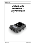
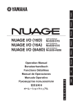
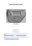
1
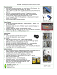
Specifications (cont)
Size l x w x h (in)
SUNRNR unit
28 x 15 x 30
Size l x w x h (cm)
71 x 38 x 76
Weight (lbs)
Weight (kgs)
260
118
Solar Panel
1.8 (depth w/j-box)
x 26.3 x 59.1
4.6 (depth w/j-box)
x 66.8 x 150.
27.5
12.5
Please contact SUNRNR of Virginia directly for technical
support or any questions concerning your SUNRNR.
Contact information is below. Units must be returned to
factory or authorized SUNRNR dealer for service.
SUNRNR
“Sun Runner”
Portable Solar/Wind Generator
STORED SUNSHINE
Your SUNRNR comes with a one year limited Warranty
which covers defects in materials or workmanship.
(Product registration required – see below).
All Warranty claims must be made in writing directly to:
SUNRNR of Virginia, PO BOX 102,
PORT REPUBLIC, VA 24471
(540) 271-3403 [email protected]
Warranty-related Shipping and Handling cost are not
covered under Warranty. Consumer is fully responsible
for paying any Shipping and Handling costs incurred.
For Product Registration, send:
name
address
phone number
model and serial number
date and place of purchase
by mail (card enclosed) to the address above, by
submitting form on website, or to [email protected]
Model: _________________________________________
Serial Number: ___________________________________
Date of Purchase: _________________________________
Purchased From: __________________________________
Keep for your records
12
10/12
User ’s Manual &
Warranty Information
SUN110, SUN240, SUN220, SUNPWR
This manual contains important information regarding
safety, operation, maintenance, storage, and warranty of
this product. Before use, read and understand all
WARNINGS, CAUTIONS, instructions, and product labels.
Failure to do so could result in personal injury or property
damage. Keep manual for reference. www.sunrnr.com
WARNING - Important Safety Information
To ensure safe and reliable service, your SUNRNR must
be operated properly. READ ALL INSTRUCTIONS
BEFORE USING THIS SUNRNR GENERATOR. Pay
particular attention to the WARNING and CAUTION
statements in this manual. The WARNING statements
identify conditions or practices that may result in personal
injury or even death. The CAUTION statements advise
against certain conditions and practices that may result in
damage to your SUNRNR and other equipment. Failure to
comply with these operating instructions will void warranty.
! WARNING !
FOR YOUR SAFETY:
Do not store or use gasoline or other flammable vapors
and liquids in the vicinity of this or any other appliance.
Read product labels for flammability and other warnings.
TO REDUCE THE RISK OF FIRE, ELECTRIC SHOCK,
EXPLOSION OR INJURY:
DO NOT locate SUNRNR in an area, room or enclosed
space where explosive or flammable fumes might be
present - NOT IGNITION PROTECTED.
DO NOT connect to AC distribution wiring. A SUNRNR
is designed for direct use by AC appliances plugged
directly in to the AC receptacles on the SUNRNR.
Remove any appliance plugs from SUNRNR outlets
before servicing appliance.
This is not a toy - KEEP AWAY FROM CHILDREN.
A SUNRNR produces ~115 or ~230 V AC power.
Always use the same safety precautions that you would
use when using a normal household outlet.
Never use damaged cords or plugs (no cuts, bare wires,
etc) in any SUNRNR or household outlet.
Never drive over, walk on, or drag any electrical cords
including cables to solar panel or other energy source.
Never leave SUNRNR near stairs, ramps, or drop-offs.
DO NOT connect the neutral AC output terminal of your
SUNRNR to ground - dangerous AC voltages can be
present between SUNRNR neutral and SUNRNR ground.
Do not drop SUNRNR or solar panel.
Specifications
Inverter
Max Continuous Power
Surge Capacity (Peak)
Waveform
Rated Input Voltage
AC Output Voltage
Efficiency
No Load Current Draw,
switch ON
AC Outlets
Solar
Panel
SUN110
5000 Watts
10000 Watts
Modified Sine
10 - 16 VDC
110V at 60Hz
90%
<1 ADC
SUN220
5000 Watts
10000 Watts
Modified Sine
10 - 16 VDC
220V at 50Hz
90%
<2 ADC
SUN240
5000 Watts
10000 Watts
Modified Sine
10 - 16 VDC
240V at 60Hz
90%
<2 ADC
4 Std No Amer
2 Universal
2 Universal
Max Power 140 (+/-5%) W;
36 cells; accessible junction box
Anodized, mount-ready
frame; 20-yr mfr warranty
Charge control is based on 3-stage charging algorithm modes: bulk
charge (highest rate), constant-voltage (pulse), and float (maintainer).
Solar Charge Controller
(LEDs only when panel connected)
POWER LED –
ON – panel properly connected,
red
normal power supply.
OFF – no power available or of
insufficient voltage.
CHARGING LED –
ON – battery charging; bulk charge
blue lightning bolt
of virtually all solar power to battery.
Flashing – panel voltage too low for
charging (insufficient daylight).
CHARGE COMPLETE LED – ON – fully charged; small float charge
green, full battery symbol
continues to maintain battery.
Battery GOOD LED – green,
Battery voltage over 12.5V+/-0.4 and
¾-full battery symbol
charging
Battery FAIR LED – yellow,
Battery voltage 11.5-12.5V+/-0.4, needs
½-full battery symbol
charging
Battery LOW LED – red,
Battery voltage 11.5V+/-0.4, needs
¼-full battery symbol
charging
Battery LOW LED –
Blown 30-amp fuse (battery
blinking red
disconnected)
Operation temperature
41-122 ºF
Operation humidity range
0-80% RH
Over temp protection (cutoff)
>176 ºF
Over temp protection (restart) <149 ºF
Battery
Sealed lead acid absorbed
glass mat (AGM) deepcycle
Realistic Storage Capacity
Manufacturer Expected Life
Time
SUN110, SUN220, SUN240, SUNPWR
8A8D 12V 245 amp hours
2000 Whrs
5 years, 150-3100 cycles dependent on
usage
11
Power Inverter Output Waveform
The AC output waveform of the inverter is modified sine wave having
characteristics similar to the sine wave shape of utility power. This type
of waveform is suitable for most AC loads, including linear and switching
power supplies used in electronic equipment, motors, and transformers.
This waveform has an RMS (root mean square) voltage of 115 volts,
which is the same as standard household power. Most AC voltmeters
(both digital and analog) are sensitive to the average value of the
waveform rather than RMS. They are calibrated for RMS voltage under
the assumption that the wave form measured will be a pure sine wave.
These meters will not read the RMS voltage of a modified sine wave
correctly, reading about 20 to 30 volts low when measuring the output.
For accurate measurement of the
output voltage of the inverter, use a
true RMS reading voltmeter such as
a Fluke 179, Fluke 79 III series,
Beckman 4410 or Triplett 4200.
Power Source Requirements
The inverter is well suited for heavy loads such as well pumps, small
compressors, small wire feed welders and other loads requiring a high
inrush starting current, high amp starting load. Induction motors, as well
as some other loads, may require two to six times their rated wattage to
start up. A SUNRNR’s inverter has a peak watt power rating that may
allow such appliances and tools to be operated safely. The equipment
needing the highest starting wattage is pumps and compressors that
start under load. This equipment can be safely tested and if an
overload is detected, the inverter will simply shut down until the
overload situation is corrected and the inverter reset.
Appliance Power Consumption: Most electrical tools, appliances and
equipment have labels that show the device’s power consumption in
amps, watts, or both. If only amps are given, Watts may be calculated
by multiplying amps times volts AC (either ~115 or ~220).
Typical Wattages (~W/hr at max continuous setting/speed/volume):
Light Bulb – 100W equivalent LED
5 (incandescent 100W)
Laptop Computer
55
CRT TV
150
Stereo/Amplifier
240
Flat Screen TV
300
Drill, Jig Saw, Sander
360
Computer and Monitor
440
Refrigerator/Freezer (comp on w/defr) 600
Furnace – gas w/ blower
750
Vacuum Cleaner, Washer
820
Coffee Maker - brewing
1000
Compact Microwave Oven
1000
10” Bench Saw
1500
Well Pump
1500
A/C (central w/compressor on)
3500
Clothes Dryer
5500
10
DO NOT allow the SUNRNR to become inverted or fall
on its sides/ends - keep upright on its wheels, handles up.
DO NOT operate SUNRNR unless it is upright as above.
SUNRNR weighs more than 250 pounds - DO NOT roll
over toes, fingers, feet, pets, or anything that might be
damaged or injured and DO NOT lift alone.
To prevent cuts from sharp edges, use gloves when
lifting SUNRNR from the bottom.
NEVER CONNECT NEUTRAL OR LINE 1, HOT LINE,
AC OUTPUT TO GROUND, NEUTRAL MUST FLOAT!
DO NOT operate SUNRNR if unit is wet; allow to dry
thoroughly before operation.
Do NOT cover or operate unit in unventilated areas.
The SUNRNR AC outlets have ground fault protection.
Always use cords and appliances with grounded, 3 prong
plugs, for maximum ground fault safety.
Cigarette lighters can fit into the 12 VDC socket,
become extremely hot, cause serious burns, or start fires –
Never touch hot end to something that might burn.
Always disconnect ALL plugs from outlets or portals by
grasping plug only - Never unplug by pulling cords.
If you see or smell smoke, sparks or fire, turn off the
SUNRNR main switch.
DO NOT plug in battery chargers for cordless power
tools if the charger carries a Warning that dangerous
voltages are present at the battery terminals.
Dangerous voltages inside unit and solar panel junction
box – DO NOT open unit or junction box.
Avoid high winds while handling solar panel.
Not approved for use with medical equipment.
CAUTIONS
NO USER SERVICABLE COMPONENTS INSIDE.
OPENING UNIT WILL VOID WARRANTY.
Do not operate over 3500 Watts continuous.
Ensure devices to be operated do not exceed Wattage
limitations and are OFF before plugging into SUNRNR.
DO NOT operate SUNRNR if it is wet.
Keep in well-ventilated area when in use.
Do NOT use with small, Ni-* battery-operated
appliances that plug DIRECTLY into AC receptacle.
3
BEST PRACTICES:
Turn off SUNRNR main switch when not in use.
Use SUNRNR and recharge relatively often or keep
SUNRNR fully charged for optimal performance.
Battery can freeze and need early replacement (not
covered by warranty) if charge not maintained during
colder months.
Keep wheels on solid surfaces.
Use LEDs, energy efficient appliances when possible.
TABLE OF CONTENTS
Introduction
4
Operation
5
Care/Maintenance
8
Troubleshooting
8
Appendices
9
Specifications
11
Introduction
The SUNRNR portable renewable energy generator has been
designed to give you silent, zero-emission quality power with
ease of use and reliability. The SUNRNR stores energy
produced by the included solar panel (or other energy generation
source) when exposed to sunlight and may be thought of like a
bank account for electricity – make withdrawals as needed,
make deposits when possible, plan a budget, and monitor your
balance. The SUNRNR may be charged either while off or while
in use to extend the run time. It may be used with or without the
solar panel, etc. connected. The auxiliary portal is provided for
charging by wind turbine or other source of energy generation.
A SUNRNR will easily run such AC loads as fans, pumps, lights,
furnaces, microwaves, power tools, refrigerators, TVs and most
other household appliances. Twelve-volt DC power for devices
like a cell phone charger is available at the auxiliary socket on
the DC end or from the AUX portal (AUX plug required).
The electricity is stored in a large 8D 245 amp-hour absorbed
glass mat (AGM) deep cycle storage battery. Battery charging
by solar panels is monitored by a charge controller (Fig 1). The
battery is sealed, but is provided with over pressure vent caps
4
Refer to the following chart for nominal voltage information and
troubleshooting. The battery voltage LCD readout provides insight into
charge status when taken into account with battery equalization (or
“resting”) information as in the chart.
Battery Condition at 77ºF
Battery during equalization charge
Battery near full charge while charging
Battery near full discharge while charging
Battery fully charged with light load
Battery fully charged with heavy load
No charge or discharge for 6 hours – 100% charged
No charge or discharge for 6 hours – 80% charged
No charge or discharge for 6 hours – 60% charged
No charge or discharge for 6 hours – 40% charged
No charge or discharge for 6 hours – 20% charged
No charge or discharge for 6 hours – Fully discharged
Battery near full discharge while discharging
Nominal Battery
Voltage 12V
Over 15
14.4 to 15
12.3 to 13.2
12.4 to 12.7
11.5 to 12.5
12.7
12.5
12.2
11.9
11.6
11.4
10.2 to 11.2
Common Audio/Visual Problems
“Buzzing” sound in audio systems: Some inexpensive stereo
systems’ power supplies may not adequately filter the modified
sine wave of the inverter, therefore emitting a buzzing sound
from speakers. Use higher quality power amplified/filtered
supply sound system.
Television interference: Although inverter is shielded, some
interference may be visible, especially with weak TV signals. Try
distancing inverter from TV equipment, using shielded antenna
cable, adjusting orientations, attaching “ferrite data line filter” to
TV power cord, and do not operate high-power devices
concurrently.
Appendices
CAUTIONS
To avoid inverter shutdown and possible damage, ensure that total
continuous power consumption of all tools and/or appliances
simultaneously powered by inverter does not exceed continuous watts
rating. Larger resistive loads, such as electric stoves or heaters, could
draw more wattage than the inverter can deliver on a continuous basis.
Also ensure start-up wattage for loads does not exceed peak watts for
more than a second. Appliances such as microwave ovens will
normally draw more than their rated current and could possibly overload
the inverter when operating simultaneously with other appliances. For
example, a 600 W microwave oven draws approximately 940 W. The
overload protection will automatically shut the unit down if the inverter’s
output capacity is exceeded continuously. If overload shutdown occurs,
turn OFF inverter, remove excessive load, and restart ON.
9
SUNPWR Power Module
Power Modules are an option for
expanding your SUNRNR system.
They are identical to SUNRNRs less
the inverters, therefore doubling the
energy generation and storage
when linked to a primary unit.
Connect a SUNPWR to a main unit
Fig 4 – Linked units
by the included large link cable with
the large red plugs (Fig 4). Plugs’
tabs prevent improper orientation. Turn master switch ON to
utilize the modules stored energy. The recharging procedure is
the same as above. A second power module may also be
connected (“daisy-chained”), tripling the system. WARNING:
Turn SUNPWR unit off before connecting or disconnecting
any large red link plug.
Care/Maintenance
A SUNRNR is virtually maintenance-free as there are no
moving parts. However, using the unit and charging the battery
whenever convenient/possible will give the battery its longest life.
Dirt, dust, haze, or shadow will degrade solar charging
considerably. Wipe panel when necessary using soft cloth
(water and mild detergent may be used). The entire panel must
be exposed at the same time for maximum energy conversion –
even 5% shadow coverage will drastically reduce charge.
ALWAYS turn master switch at DC end to OFF when not in
use. The parasitic load if left ON will deplete a fully charged
battery by about 1-2 amp/hr (~10 days).
Troubleshooting
Inverter Problems (Inverter power ON)
No output/Volt bar graph lower red: Battery <10 VDC (recharge)
No AC output/Over-temp indicator lit: Thermal shutdown (turn
off, reduce load, allow cool down, restart).
Motorized power tool will not start: Excessive start-up load – tool
incompatible with inverter.
Power tool operating speed not correct: Purely inductive load add resistive load by operating incandescent lamp concurrently.
Charging Problems (Battery not recharging): Check 30-amp fuse
for charging portal in use (switch upper and lower to verify).
Replace with similar specification fuse if necessary.
8
that will allow battery gases (i.e. hydrogen) to escape if the
battery becomes over-pressurized due to faults. The battery will
normally NOT VENT any battery gases in normal use.
A SUNRNR unit includes one (or two) weatherproof solar
panel(s) with 30-foot, quick-connect cable. Each panel is rated
at 140 Watts/hour when exposed to bright sunlight. The solar
panel may still provide charge, but at a lesser rate, when
exposed to any light source. Moderate charging may possibly
be achieved even on cloudy days. Two panels are
recommended for reduced charging time. (Two panel
maximum.) It takes almost 12 hours of bright sunlight to
fully charge a fully-depleted SUNRNR when using two
panels. The anodized, rugged panel frames are made for
outside mounting or for use as portable, stand-alone panels
when placed anywhere facing the sun, even inside in a window.
ANY shade on any part of a panel decreases its
performance considerably.
The SUNRNR may also be charged by 12VDC sources other
than solar or by our AC/DC charger through the AUX portal.
Charging is limited to 30 amps by accessible fuses protecting
the small red plug portals. (See Manual Supplement.)
Operation
To operate a SUNRNR:
1) Turn on the main (12V DC) switch located in the upper right
hand corner of the DC end (Fig 1). This switch should be turned
"OFF" when the unit is not in use.
2) Turn on the inverter switch located at the AC end of the
SUNRNR (Figs 2a, 2b).
3) Ensure the AC appliance(s) are switched off and simply plug
into the outlets before using as desired. Try to avoid using
extension cords. If an extension cord is required, use a 12
gauge 3-prong grounded extension cord no longer in length than
necessary (lessens power loss).
Fig 1 – DC End
Charge controller (solar);
Master switch;
Charging portals;
30-amp fuses (top SOLAR,
bottom AUX);
Large 175-amp red link
portals;
12VDC auxiliary socket
5
The Current Output bar graph indicates AC load being supplied
to the devices being run - green for normal operation and upper
red zone during temporary surge output. See recommended
max output per outlet in Fig 2. The overload indicator will light
when load exceeds limits and inverter will automatically shut
down. Turn devices and inverter off, reduce load, and restart.
The inverter also has a cooling fan that is thermally activated
and may be heard operating intermittently when in normal use.
If thermal limit exceeded, the over-temp indicator will light and
the inverter will shut down until cooled.
Fig 2a – AC End, 110VAC/60Hz Inverter (SUN110)
Fig 2b – AC End, 220VAC/50Hz Inverter (SUN220, “International”)
or 240VAC/60Hz Inverter (SUN240, “well pump”)
For information regarding the terminal block and/or usage other
than stand-alone, please call or have your certified electrician
call Alan at 540-234-0164.
Inverter: The inverter features bar graph displays for AC load
(Current Output) and DC status (Volts). When fully charged,
battery voltage will be approximately 14V (see table on pg 9). At
10.7 volts, the inverter’s battery voltage bar graph will read in the
lower red zone and an audible low battery warning will sound.
To extend run time, reduce AC load if possible or connect
charging source. The SUNRNR will continue to run while
beeping until the inverter automatically shuts down for low
battery voltage at about 10.0 volts, protecting the AC loads from
under voltage and the battery from complete discharge.
If the battery nears overcharge (bar graph in upper red zone),
the inverter will beep and shut down until the charging source is
removed and the battery voltage is allowed to drop to "normal".
6
Charging via solar: Place panel in
best direct sunlight. Plug solar
panel’s cord with small red plug into
SOLAR (right) portal on DC end
(Fig 3). Tabs on red plugs ensure
proper orientation. When the panel is
connected and has light, the digital
charge controller’s LED status lights
will activate as electricity flows from
the solar panel through the charge
controller to the SUNRNR battery.
LED lights on the charge controller
give a general indication of
Fig 3 – Charging plugs/portals
battery status (¼-, ½-, ¾-full,
and fully-charged). The controller’s status lights and symbols
are described fully under Specifications. The controller’s digital
LCD readout displays regardless of panel connection and
indicates battery voltage when the three-position slide switch is
set to “Voltage” or incoming charge in amps when set to
“Current”. The current/amp reading should be used for directing
the solar panel to maximize charge rate. The LCD digital current
display will read over 8 amps in bright, direct sunlight using one
panel (dropping significantly as the battery approaches full
charge) and about 0.4 amps when charging through clouds.
Slide switch to OFF in middle when not in use.
Charging via wind turbine, grid, etc: Connect energy source
at small red AUX (left) portal. This portal bypasses the solar
charge controller and will not provide power for its LED charge
indicator lights. Energy source must be pre-wired with AUX plug
and should have internal charge controller. (See Manual
Supplement.) This portal may also be used for 12VDC, 30-amp max
output by way of an AUX plug.
7
SUNRNR
“Sun Runner”
Portable Solar/Wind Generator
User’s Manual Supplement
SUNRNR OPTIONS & ACCESSORIES
This supplement becomes part of the SUNRNR User’s Manual and contains important information regarding safety and
operation of SUNRNR-related products. Keep for reference. Before use of products, read and understand all
WARNINGS, CAUTIONS, instructions, and labels. Failure to do so could result in personal injury or property damage.
ALL WARNINGS, CAUTIONS, BEST PRACTICES IN USER’S MANUAL APPLY TO THIS SUPPLEMENT
AUXILIARY PLUG
Quick-connect plug with 2’ wired cable for use in AUX portal of a SUNRNR. Bare end may
be wired to alternative 12VDC (400W max) recharging methods such as wind or water
turbine. Charging is limited to 30 amps by the fuse protecting the AUX portal. Input source
should have internal regulator since AUX portal bypasses unit’s solar charge controller.
Plug may also be used for output to power 12VDC, 30-amp max devices.
Black wire = negative. White wire = positive.
AC-DC CHARGER
Safely recharge a SUNRNR from the grid if renewable source is unavailable or
inconvenient. Pre-wired to plug into AUX portal. Automatic internal controller protects from
overcharge. Place switches on “Automatic” and “10-amp” before use.
WIND or WATER TURBINE
See www.sunrnr.com/links for suggested turbines. AUX plug above required for quickconnect of turbine to SUNRNR through AUX portal. Turbines must have internal charge
regulator and be rated for (or used at) 400W or less.
BICYCLE STAND CHARGING SYSTEM
Pre-wired for plugging into AUX portal. Quick-attach of bicycle rear wheel. Bicycle and
energetic human not included ;)
NEMA PLUG PS5466-X
Plug fits SUN220 and SUN240 recepticles. For use by certified electrician - requires new
outlet circuit for switching of equipment from the grid to a SUNRNR.. Please call 540-2340164 for assistance.
LINK CABLE
Allows the sharing of stored battery power between units. Turn SUNRNR units’ master
switches off before connecting or disconnecting any large red link plug.
SUNLION
Special order option – custom, system-specific notes will be provided.
FUSES
Solar (top) and AUX (bottom) charging portals protected by TRM30, 30A, 250V fuses.
Twist fuse holder open and replace with similar specification fuse.
AC TERMINAL BLOCK FOR HARDWIRING 5000W OUTPUT
For use by certified electrician. Please call 540-234-0164 for assistance.