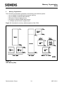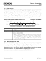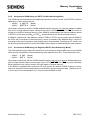
1
On-Chip Peripheral Components
C504
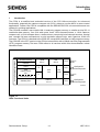
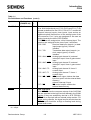
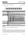
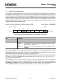
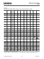
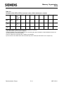
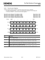
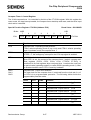
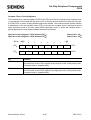
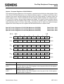
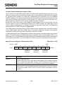
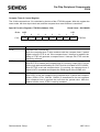
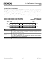
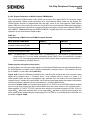
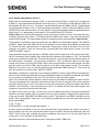
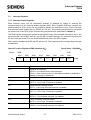
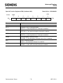
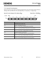
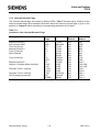
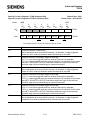
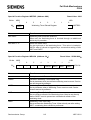
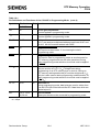
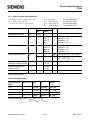
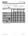
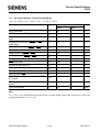
Capture/Compare Channel Mode Select Registers
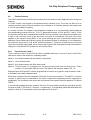
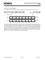
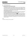
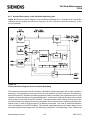
The capture/compare channels of the CAPCOM unit can operate individually either in compare
mode or in capture mode. The CMSEL0 and CMSEL1 registers contain the mode select bits for the
CAPCOM unit.
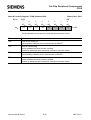
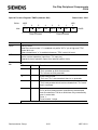
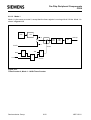
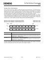
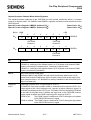
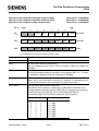
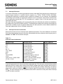
Special Function Register CMSEL0 (Address E3H)
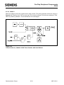
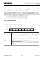
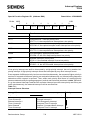
Special Function Register CMSEL1 (Address E4H)
Bit No. MSB
7
E3H
6
5
4
3
2
1
LSB
0
CMSEL CMSEL CMSEL CMSEL CMSEL CMSEL CMSEL CMSEL
12
11
13
02
01
00
10
03
CAPCOM
Channel 1
7
E4H
Reset Value : 00H
Reset Value : 00H
6
ESMC NMCS
CMSEL0
CAPCOM
Channel 0
5
4
0
0
3
2
1
0
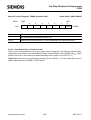
CMSEL CMSEL CMSEL CMSEL
23
22
21
20
CMSEL1
CAPCOM
Channel 2
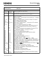
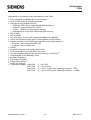
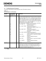
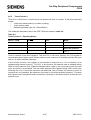
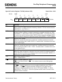
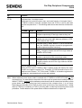
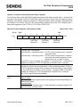
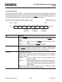
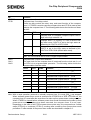
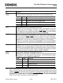
Bit
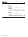
Function
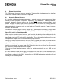
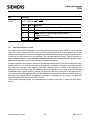
ESMC
Enable software controlled multi-channel PWM modes
If ESMC=0, switching of the follower state in 4-/5-/6-phase multi-channel PWM
mode is controlled by compare timer 1 reaching its period value.
If ESMC=1, switching of the follower state in 4-/5-/6-phase multi-channel PWM
mode is controlled by bit NMCS.
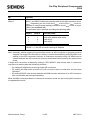
NMCS
Next multi-channel PWM state
Setting bit NMCS (with ESMC set) will select the follower state in the 4-/5-/6phase multi-channel PWM mode, which is taken into account at the output pins,
when compare timer 1 is 0. Bit NMCS is reset by hardware in the next clock cycle
after it has been set.
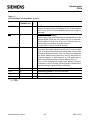
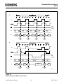
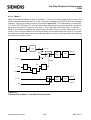
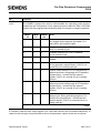
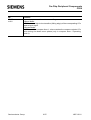
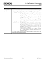
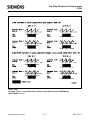
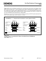
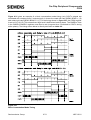
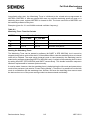
CMSELx3
x=0-2
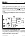
Switching compare timer 2 output signal to COUTx
If CMSELx3 is set and compare mode is selected for the outputs COUTx, the
output signal of the 10-bit compare unit, typically a higher frequency signal, is
switched (modulated) to the COUTx pin. The state of the corresponding COINI bit
at the start of compare timer 1 defines the logic level of the CAPCOM channel
output signal at iwhich the COMP output signal is output to COUTx.
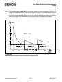
COINI is set :
The COMP output is switched to COUTx during the low phase
of the CAPCOM channel X signal.
COINI is cleared : The COMP output is switched to COUTx during the high phase
of the CAPCOM channel X signal.
Semiconductor Group
6-51
1997-10-01